Transcription
Construction Innovation 2005; 5: 99–1144DCAD-Safety: visualizing project schedulingand safety planningDamrong Chantawit, Bonaventura H.W. Hadikusumo, and Chotchai Charoenngam ConstructionEngineering and Infrastructure Management, Asian Institute of Technology, Bangkok, ThailandSteve Rowlinson Department of Real Estate and Construction, The University of Hong Kong,Hong KongSubmitted 5 January 2004; accepted 14 September 2004Abstract: Safety planning in construction project management is separated from otherplanning functions, such as scheduling. This separation creates difficulties for safetyengineers to analyse what, when, why and where safety measures are needed forpreventing accidents. Another problem occurs due to the conventional practiceof representing project designs using two-dimensional (2D) drawings. In this practice, anengineer has to convert the 2D drawings into three-dimensional (3D) mental pictures whichis a tedious task. Since this conversion is already difficult, combining these 2D drawingswith safety plans increases the difficulty. In order to address the problems, 4DCAD-Safety isproposed. This paper discusses the design and development of 4DCAD-Safety applicationand testing its usefulness in terms of assisting users in analysing what, when, where andwhy safety measures are needed.Key words: accident prevention; computer aided simulation; computer graphics; hazards;safetyIntroductionSafety is considered as one of the project’s success factors. Poor safety management mayresult in accidents that impact on human, economic, and legal issues. The human impactinvolves both physical and psychological pains suffered by worker and his family. Theeconomic impacts increase direct and indirect costs of the organization. In addition, there isthe legal impact that relates to a breach of safety regulations. Therefore, it is necessary toconsider safety and health as a project success factor along with other project success factors,such as time, project and quality.Safety management covers from planning to implementation. Safety planning must beconducted prior to a construction activity for determining safety measures needed. Theplanning is the first fundamental step for managing safety. However, there is a problem withthe conventional safety planning in construction project management.The problem is related with loose relationships of plans: safety plan, project scheduling,and project drawings that are in 2D representation. This problem causes difficulties in usingand analysing safety plans. For this reason, Kartam (1997) integrated safety plan with projectAddress for correspondence: B.H.W. Hadikusumo, Assistant Professor, Construction Engineering and Infrastructure Management, Asian Institute of Technology, Bangkok, Thailand. E-mail: kusumo@ait.ac.th# 2005 Edward Arnold (Publishers) Ltd10.1191 1471417505ci091oa
100 D. Chantawit et al.scheduling. However, project design (i.e., drawings) was not included in his study. Withoutintegrating project design, safety engineer will have difficulties in visualizing how the site willlook; and this is important in determining safety hazards occurring.This paper discusses our 4DCAD-Safety research that aims to integrate 4DCAD (i.e.,3DCAD objects and project time schedule) and construction site safety plan for assistingusers in analysing and utilizing safety plans in terms of what, when, where, and why a safetymeasure is needed. This paper explains how a 4DCAD-Safety application is designed,developed, and tested.Construction safety planningSafety planning plays its important roles in construction project management for reducingunnecessary cost and delays related to undesired accidents. Safety planning ensures thatsafety will be taken into account along with costs, schedules, quality and other important jobgoals.Safety planning includes identifying all potential hazards and hazardous operations andsafety measures. This safety planning can be enhanced into safety risk management systemby adding more tasks: identifying safety hazards, classifying risks, controlling the risks andmonitoring the implementation. Among these tasks, safety hazard identification is the mostimportant, since failure to identify safety hazards means safety measures are not adequatelyinvestigated.Safety planning is traditionally managed separately from project planning scheduling task.However, there must be a method to link these planning tasks. There are two reasons forexplaining why the link is important. First, the safety plans must be linked with theconstruction schedule because safety engineers need to identify when safety measures onthe safety plans must be used. Secondly, the safety engineers have to use constructiondrawings for developing the safety plans because these drawings have the information relatedto why and where safety measures are chosen. Kartam (1997) has developed IntegratedKnowledge Intensive System for Construction Safety and Health Performance Control(IKIS-Safety System) that integrates safety and health requirement (i.e., safety plan) into aCPM-based project schedule. This integration provides a way to manage safety and healthperformance proactively rather than reactively, and alert construction manager and allinvolved parties when reviewing the CPM schedule (MacCollum 1995: 130; Kartam1997). IKIS-Safety system helps users to know when a safety measure (i.e., what) is usedsince it is integrated with project scheduling; however, IKIS-Safety does not support adequateinformation for analysis. In our study, we consider that providing adequate informationfor safety engineers to analyse a safety plan in terms of why, when, where a safety measure(i.e., what) is important.In order to provide adequate information, integrating the safety plan with 4DCAD, i.e., 3Dobject plus scheduling, is crucial. The 3D object should be used because it provides WhatYou-See-Is-What-You-Get (WYSIWYG) benefit. In conventional construction project, mostof the objects are represented using 2D drawings. Collier (1994) noted that this 2Drepresentation is a bottleneck since engineers have to convert this drawing into 3D mentalpicture which is a tedious task. Since creating this 3D mental picture is already a tedious task,
4DCAD-Safety101combining the 2D drawing with safety planning increases the difficulty. As a solution,3D model computer representation can be adopted.4DCAD technology for managing construction projectsKoo and Fischer (2000) defined Four-Dimensional Computer Aided Design (4DCAD) as aresult of integrating 3D objects to the fourth dimension, time. The 3D and time integrationallows users to run a visualization of the planned construction process of the project. The firstidea was conceived in 1986–1987 when Bechtel collaborated with Hitachi Ltd to develop theConstruction CAE 4D Planner software (Simons, 1988 cited in Rischmoller, 2000). The 4Dmodel aims to overcome deficiencies of the traditional planning and control, such as barcharts and network diagrams, that do not effectively represent and communicate the spatial,temporal, and nonprecedence information.In conventional project planning, a contractor has to abstract the visual description of aproject design into a textual description of activities and construction schedule. Later at theconstruction stage, engineers have to visually conceptualize the sequence of construction, andthe 3D mental model of construction objects for construction purposes. In 4D environment,this tedious process is eliminated since the 4D model explicitly represents the relationshipbetween the description of a facility (3D object) and the construction schedule (McKinneyand Fischer, 1998).4DCAD facilitates 3D construction products to be visualized along with constructionprocesses on a computer screen therefore users need not to interpret construction productsand processes in their minds. In other words, users can visualize the construction processes, asthey would be actually carried out in reality. Potential benefits of 4DCAD have been extendedby adding additional dimension, such as resources constraint management (Sripasert andDawood, 2002), and nD-modelling (Rowlinson and Yates, 2003; Lee et al., 2004).The benefit of 4DCAD can also be used for safety planning purposes in which the 4DCADtechnology can be integrated with safety plan for providing safety engineers for analysingwhat, when, where, and why a safety measure is needed. This integration is called4DCAD-Safety.4DCAD-SafetySystem functionalities4DCAD-Safety application is designed to facilitate safety engineers to analyse and utilize asafety plan. For this purpose, necessary information, i.e., 1) what safety measures are needed,2) why, 3) where, and 4) when they are needed, must be provided. The information relatedwith type of safety measures can be stored in a database, so that engineers can retrieve thisinformation when they need it for planning safety measures in a project. When the engineershave to determine type of safety measures need to be used, their decision is influenced by twoaspects: the physical condition of the project, represented in project designs; and the projectprogress, represented in a project schedule. The physical condition affects engineers’ decisionin terms of where and why the safety measures are needed. Similar tasks conducted indifferent conditions may need different safety measures, e.g., constructing a column at the
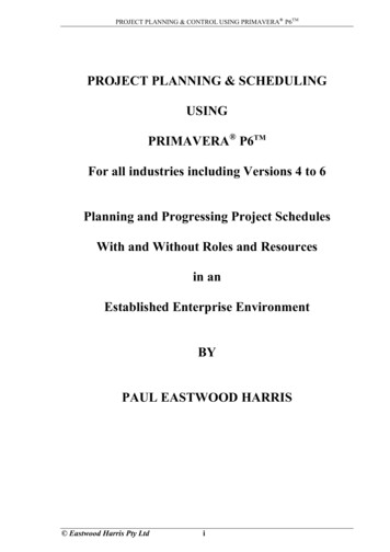
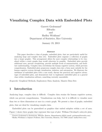
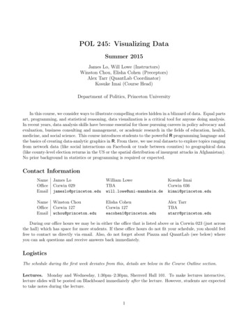
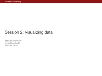
102 D. Chantawit et al.perimeter of a building has different hazard exposure compared to constructing a column atthe centre of the building. This means safety engineers need to know where the safetymeasures will be used in order to analyse why they need to be used. The other aspect, projectprogress, also affects the reason for why a safety measure is needed because project progressmay temporarily creates different safety hazards.In order to include what, why, where, and when aspects, the 4DCAD-Safety is equippedwith three main components: 1) 4DCAD simulator, 2) safety library and plan, and3) 4DCAD-Safety simulator. The 4DCAD simulator is used to simulate the project progressfor a specific date. The safety library and plan are used to determine what types ofsafety measures are needed. Finally, the 4DCAD-Safety simulator is used to simulate specificsafety measures chosen for a specific project progress. In other words, the simulationgenerates the project progress at a specific date and safety measures related; and this isuseful for the engineers to analyse what safety measures are needed, why, when and wherethey are needed.A case example for illustrating the 4DCAD-Safety is presented in Appendix A.4DCAD simulation. The 4DCAD simulation engine aims to generate, manipulate andsimulate the 4DCAD model. Before generating the 4DCAD model of the whole project, allsubschedules from the subcontractors need to be combined into one main schedule otherwisesome construction products may not be shown during the simulation. Hence, the first featureprovided in this function is to combine subschedules of subcontractors into a main scheduleof a contractor. (Note: this feature is optional.)The 4D simulation can be obtained by making the 3D objects visible or invisible accordingto the construction scheduling. Ongoing and completed 3D objects are set as visible while therests are set as invisible. The ongoing objects are represented in blue colour, while thecompleted objects are in green.Safety library and planning function. A safety plan contains safety measures to preventaccidents. In order to generate a safety plan, 4DCAD-Safety is equipped with two safetyfeatures: safety library and safety planning.A safety library contains several safety data collected from regulatory standards and safetyengineers’ experience, e.g., installing a guardrail to protect workers from falling from an openslab. Due to the nature of a library as a storage function, the safety library may have a lot ofsafety data; and this creates difficulties for a user to find the specific safety data in the safetylibrary. For solving this problem, a keyword system is used to filter safety data. For example,when a user filters the safety library with the ‘Piling’ keyword, every safety data holding thiskeyword will be shown, such as 1) use earmuff, 2) use safety helmet, and 3) use eyesprotection.A safety plan is created by assigning the safety data, compiled from the safety library, intoan activity. The relationship between construction task (or activity) and safety data isillustrated in Figure 1.System architecture4DCAD-Safety system architecture consists of four parts (see Figure 2): 1) MS ProjectTM,2) AutoCADTM or AutoDesk Architecture DesktopTM, 3) Database, and 4) the
4DCAD-Safety103Figure 1 4DCAD-Safety: safety library and safety plan4DCAD-Safety application (i.e., an interface application). The construction project scheduling is created using MS ProjectTM software. The advantage of using MS ProjectTM is in itsability to export a schedule file to a database file using an ODBC (Open DatabaseConnectivity) function; and therefore the construction schedule developed using MS Projectcan be easily converted into a MS Access database. The system database is designed to storethree categories of data: 1) safety plan, 2) imported construction schedules, and 3) 3D objectsgroup. For visualizing construction products, AutoCADTM software is used for developingthe 3D computer objects as well as displaying them for 4D simulation purpose. Reasons forchoosing AutoCAD or AutoDesk are: 1) it supports functions that can be accessed usingprogramming languages, such as Visual Basic, and 2) this software is commonly used inthe AEC industry. One important function for the purpose of 4D simulation is ‘visibility’property of AutoCAD in which this property can be turned-off to hide an object, and
104 D. Chantawit et al.Figure 2 4DCAD-Safety system architectureturned-on to display an object. In addition, rendered images in the AutoCAD can be saved inDFX file which then can be open as 3D objects using WorldUpTM, a virtual reality software.Viewing 3D objects in World Up facilitates a better visualization since user is providedwith sophisticated walkthrough mechanism to explore the 3D objects. The last part,
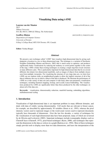
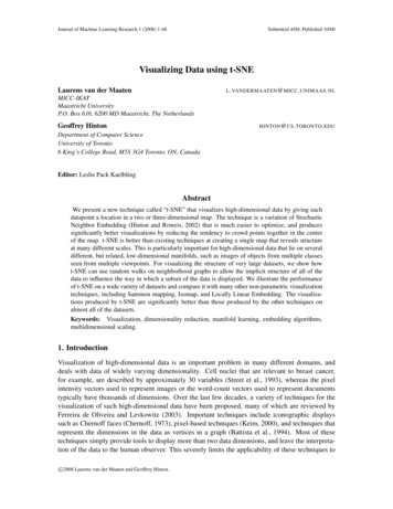
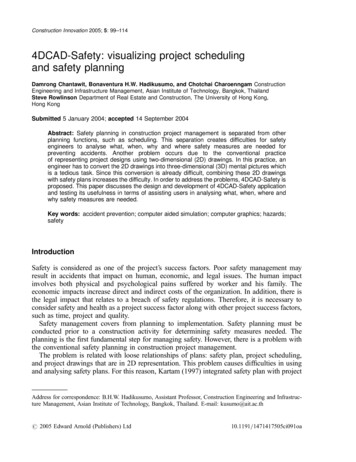
4DCAD-Safety1054DCAD-Safety interface, developed using Visual Basic programming language, aims tointegrate the system database and AutoCADTM or AutoDeskTM. ADO technology thatconnects objects (e.g., a list box, a combo box, and so on) to the system database throughMS Jet OLEDB 4.0 Provider is adopted in this application. In relation to the connection between the 4DCAD-Safety interface and AutoCADTM, this study utilized ActiveXtechnology to control every object, method, property, and event of AutoCADTM.Database design. The 4DCAD-Safety system database was developed using a relationaldatabase by using MS Access application. Its data can be mainly categorized into three maingroups: products, processes, and safety plan. Figure 3 illustrates the database structure of4DCAD-Safety system that consists of main tables (i.e., entities): ‘Group’, ‘4DLink’, ‘Task’,‘SafetyLink’, ‘SafetyLibrary’, and ‘SafetyKeyword’.‘Task’ table is needed to store main scheduling data from the MS project: TaskID, WBS,Task Name, Start Date, and Finish Date. From MS project schedule, this data must beexported to a MS Access database file. All construction activities in the MS Access databasemust be assigned into groups because some of the activities are not represented in the 3Dmodels. For example, constructing column activity is usually elaborated into four activities:installing rebar, installing formwork, concreting, and stripping off the formwork; and this fouractivities can be grouped together to represent ‘constructing column’ activity which is linkedinto a 3D model of the column (see Figure 3). In order to group tasks from the ‘Task’ tableand assign them to relate with a group of 3D objects, an additional entity so called 4DlinkFigure 3 4DCAD-Safety: linking 3D objects to databaseNote: The diagram illustrates only ID, Primary Key and Foreign Key attributes and their relationships.
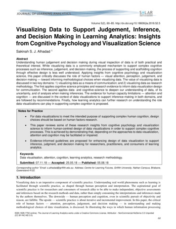
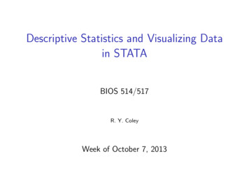
106 D. Chantawit et al.table is created. In this 4Dlink, the relationship between ‘Group’ and ‘Task’ table is set as ‘agroup can contain many tasks, but one task can be a part of a group only’.The ‘Group’ table stores data of 3D objects such as group name, WBS, and work area.One group might contain one or more 3D objects that are similar and must be built at thesame time, for example, a group of second floor slabs, which represent slabs from differentareas.In relation to safety planning, the ‘SafetyLibrary’ table is created as the library of safetydata. It stores records of predefined safety measures collected from regulatory standard andsafety engineers’ experience. For example, install a guardrail to protect workers to fall froman open slab. This safety library is used to create a safety plan stored in a composite entity,‘SafetyLink’ table. This table relates several safety data in the library with a construction taskin ‘Task’ table. This enables safety measures in a safety plan to be displayed along withconstruction products and construction processes being simulated in the 4D simulation. Forexample, the roof truss installation task needs some safety measures such as equipping asafety helmet, and providing a safety belt. When the 4D simulation reaches roof objects(construction products) and roof truss installation tasks (construction processes), these safetymeasures will be displayed.The last table, ‘Safety Keyword’ aims to assist users to list the specific records of safetylibrary based on their keywords, e.g., list all records of safety library related to a task, thenusers can choose suitable safety measures displayed. For example, when the users use‘excavation’ keyword, the database will suggest safety helmet and install a temporary shoring,then the user may choose which measures are suitable.4DCAD-Safety interface. The 4DCAD-Safety interface, developed using Visual Basicprogramming language, is designed for integrating system database and AutoCADTM orAutoDeskTM. The interface is mainly divided into three parts: 1) 4DCAD interface (see area 1in Figure 4), 2) safety interface (see area 2 in Figure 4), and 3) viewing part (see area 3 inFigure 4).The 4DCAD interface is designed for controlling the 4D components consisting ofobject groups, related tasks, and lists of tasks for providing the 4D generating functionand the simulation function. The 4D generating function aims to generate relationshipsbetween the object groups and their related tasks, while the simulation functionaims to run 4DCAD-Safety simulation. These two functions are the main objective of thisapplication.The safety interface is created for communicating a safety plan to user when its related4DCAD model is being simulated (i.e., being constructed in real world). Moreover it alsoenables a user to develop a new or modify an existing safety library as well as integrate safetyplans with 4DCAD model.The viewing part, AutoCADTM or AutoDeskTM application, is to display 3D objects and4D simulation. Each interface is designed to work consistently with others. For example,when, according to the scheduling, fourth columns are on being constructed (in the section 1of Figure 4), the viewing part will display the columns being constructed (in the section 2 ofFigure 4) as well as the safety measures related (in the section 2 of Figure 4).The 4DCAD system can be further expanded into a virtual reality visualization byexporting the simulated 3DCAD into a virtual reality object (Figure 5). User can easilydoes a walkthrough to any location in the simulated construction progress. This virtual
4DCAD-Safety107Figure 4 The interface of 4DCAD-Safety application: 1) scheduling, object grouping and general menu interface, 2)safety interface, and 3) 3D object viewerFigure 5 Visualizing simulated 4DCAD in virtual reality technology p
4DCAD-Safety: visualizing project scheduling and safety planning Damrong Chantawit, Bonaventu