Transcription
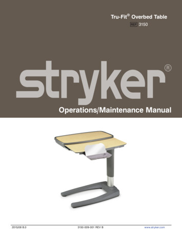
Tru-Fit Overbed Table3150Operations/Maintenance Manual2015/08 B.03150-009-001 REV Bwww.stryker.com
Table of ContentsIntroduction . . . . . . . . . . . . . . . . . . . . . . . . . . . . . . . . . . . . . . . . . . . . . . . . . . . . . . . . . . . . . . . . . . . . . . . . . . . . . 4Intended Use . . . . . . . . . . . . . . . . . . . . . . . . . . . . . . . . . . . . . . . . . . . . . . . . . . . . . . . . . . . . . . . . . . . . . . . . 4Specifications . . . . . . . . . . . . . . . . . . . . . . . . . . . . . . . . . . . . . . . . . . . . . . . . . . . . . . . . . . . . . . . . . . . . . . . . 4Warning / Caution / Note Definition . . . . . . . . . . . . . . . . . . . . . . . . . . . . . . . . . . . . . . . . . . . . . . . . . . . . . . . . 5Symbols . . . . . . . . . . . . . . . . . . . . . . . . . . . . . . . . . . . . . . . . . . . . . . . . . . . . . . . . . . . . . . . . . . . . . . . . . . . . . . . 5Summary of Safety Precautions . . . . . . . . . . . . . . . . . . . . . . . . . . . . . . . . . . . . . . . . . . . . . . . . . . . . . . . . . . . . . . 6Operations . . . . . . . . . . . . . . . . . . . . . . . . . . . . . . . . . . . . . . . . . . . . . . . . . . . . . . . . . . . . . . . . . . . . . . . . . . . . . 7Single-top With or Without Optional Vanity Operation . . . . . . . . . . . . . . . . . . . . . . . . . . . . . . . . . . . . . . . . . . . 7Split-top With Optional Vanity Operation . . . . . . . . . . . . . . . . . . . . . . . . . . . . . . . . . . . . . . . . . . . . . . . . . . . . 8Clip Operation . . . . . . . . . . . . . . . . . . . . . . . . . . . . . . . . . . . . . . . . . . . . . . . . . . . . . . . . . . . . . . . . . . . . . . . 9Bin Operation . . . . . . . . . . . . . . . . . . . . . . . . . . . . . . . . . . . . . . . . . . . . . . . . . . . . . . . . . . . . . . . . . . . . . . . . 10Preventative Maintenance . . . . . . . . . . . . . . . . . . . . . . . . . . . . . . . . . . . . . . . . . . . . . . . . . . . . . . . . . . . . . . . . . 11Checklist . . . . . . . . . . . . . . . . . . . . . . . . . . . . . . . . . . . . . . . . . . . . . . . . . . . . . . . . . . . . . . . . . . . . . . . . . . 11Cleaning . . . . . . . . . . . . . . . . . . . . . . . . . . . . . . . . . . . . . . . . . . . . . . . . . . . . . . . . . . . . . . . . . . . . . . . . . . . . . . 11Troubleshooting Guide . . . . . . . . . . . . . . . . . . . . . . . . . . . . . . . . . . . . . . . . . . . . . . . . . . . . . . . . . . . . . . . . . . . . . 12Service Information . . . . . . . . . . . . . . . . . . . . . . . . . . . . . . . . . . . . . . . . . . . . . . . . . . . . . . . . . . . . . . . . . . . . . . . 13Optional Storage Compartment Replacement . . . . . . . . . . . . . . . . . . . . . . . . . . . . . . . . . . . . . . . . . . . . . . . . 13Primary Top Replacement (Single-top and Single-top With Vanity Only) . . . . . . . . . . . . . . . . . . . . . . . . . . . . . 13Primary Top Replacement (Split-top With Vanity Only) . . . . . . . . . . . . . . . . . . . . . . . . . . . . . . . . . . . . . . . . . . 14Secondary Top Replacement (Split-top Only) . . . . . . . . . . . . . . . . . . . . . . . . . . . . . . . . . . . . . . . . . . . . . . . . . 14Upper Column Replacement . . . . . . . . . . . . . . . . . . . . . . . . . . . . . . . . . . . . . . . . . . . . . . . . . . . . . . . . . . . . . 15Gas Spring Replacement . . . . . . . . . . . . . . . . . . . . . . . . . . . . . . . . . . . . . . . . . . . . . . . . . . . . . . . . . . . . . . . 15Caster Assembly Replacement . . . . . . . . . . . . . . . . . . . . . . . . . . . . . . . . . . . . . . . . . . . . . . . . . . . . . . . . . . 16Caster Replacement . . . . . . . . . . . . . . . . . . . . . . . . . . . . . . . . . . . . . . . . . . . . . . . . . . . . . . . . . . . . . . . . . . 16Base Cover Replacement . . . . . . . . . . . . . . . . . . . . . . . . . . . . . . . . . . . . . . . . . . . . . . . . . . . . . . . . . . . . . . . 17Vanity Tray Replacement (Single-top Only) . . . . . . . . . . . . . . . . . . . . . . . . . . . . . . . . . . . . . . . . . . . . . . . . . . 18Vanity Tray Replacement (Split-top Only) . . . . . . . . . . . . . . . . . . . . . . . . . . . . . . . . . . . . . . . . . . . . . . . . . . . . 18Vanity Tray Mirror Replacement . . . . . . . . . . . . . . . . . . . . . . . . . . . . . . . . . . . . . . . . . . . . . . . . . . . . . . . . . . 19Single-top Overbed Table Assembly, Without Vanity . . . . . . . . . . . . . . . . . . . . . . . . . . . . . . . . . . . . . . . . . . . . . . 20Single-top Overbed Table Assembly, With Vanity . . . . . . . . . . . . . . . . . . . . . . . . . . . . . . . . . . . . . . . . . . . . . . . . 23Split-top Overbed Table Assembly, Without Storage . . . . . . . . . . . . . . . . . . . . . . . . . . . . . . . . . . . . . . . . . . . . . . 26Single-top Overbed Table Assembly, With Storage . . . . . . . . . . . . . . . . . . . . . . . . . . . . . . . . . . . . . . . . . . . . . . . 30Single-top Overbed Table Assembly, With Vanity, With Storage . . . . . . . . . . . . . . . . . . . . . . . . . . . . . . . . . . . . . . 34Split-top Overbed Table Assembly, With Storage . . . . . . . . . . . . . . . . . . . . . . . . . . . . . . . . . . . . . . . . . . . . . . . . . 39Gas Spring . . . . . . . . . . . . . . . . . . . . . . . . . . . . . . . . . . . . . . . . . . . . . . . . . . . . . . . . . . . . . . . . . . . . . . . . . . . . 44Warranty . . . . . . . . . . . . . . . . . . . . . . . . . . . . . . . . . . . . . . . . . . . . . . . . . . . . . . . . . . . . . . . . . . . . . . . . . . . . . . 45One Year Warranty . . . . . . . . . . . . . . . . . . . . . . . . . . . . . . . . . . . . . . . . . . . . . . . . . . . . . . . . . . . . . . . . . . . 45To Obtain Parts and Service . . . . . . . . . . . . . . . . . . . . . . . . . . . . . . . . . . . . . . . . . . . . . . . . . . . . . . . . . . . . 45Return Authorization . . . . . . . . . . . . . . . . . . . . . . . . . . . . . . . . . . . . . . . . . . . . . . . . . . . . . . . . . . . . . . . . . . 45Damaged Merchandise . . . . . . . . . . . . . . . . . . . . . . . . . . . . . . . . . . . . . . . . . . . . . . . . . . . . . . . . . . . . . . . . 45International Warranty Clause . . . . . . . . . . . . . . . . . . . . . . . . . . . . . . . . . . . . . . . . . . . . . . . . . . . . . . . . . . . 45Service Contract Coverage . . . . . . . . . . . . . . . . . . . . . . . . . . . . . . . . . . . . . . . . . . . . . . . . . . . . . . . . . . . . . 46Service Contract Programs . . . . . . . . . . . . . . . . . . . . . . . . . . . . . . . . . . . . . . . . . . . . . . . . . . . . . . . . . . . . . 46Return To Table of Contentswww.stryker.com3150-009-001 REV B3
IntroductionINTENDED USEThis manual is designed to assist you with the maintenance of Stryker Overbed Table, Model 3150. Carefully readthis manual thoroughly before using the equipment or beginning maintenance on it. To ensure safe operation of thisequipment, it is recommended that methods and procedures be established for educating and training staff on the safeoperation of this product.SPECIFICATIONS* Safe Working Load25 lbsOVERBED TABLE WITHOUT OPTIONAL STORAGE COMPARTMENTSingle-top Without Vanity Single-top With Vanity Split-top With VanityBase Length32”32”32”31” / 17.5”31” / 17.5”31” / 17.5”27” / 43.75”27” / 43.75”29” / 45.5”Weight of Table43 pounds50 pounds61 poundsWeight Capacity of Table *75 pounds75 pounds75 poundsOverall Table Top Length/WidthMinimum/Maximum Table Top HeightOVERBED TABLE WITH OPTIONAL STORAGE COMPARTMENTSingle-top Without Vanity Single-top With Vanity Split-top With VanityBase Length32”32”32”Overall Table Top Length/Width42.75” / 17.5”42.75” / 17.5”42.75” / 17.5”Minimum/Maximum Table Top Height27” / 43.75”27” / 43.75”29” / 45.5”Weight of Table68 pounds75 pounds86 poundsWeight Capacity of Table *75 pounds75 pounds75 poundsSAFE OPERATING LOADS OF OPTIONAL STORAGE COMPARTMENTTop ShelfBottom Shelf20 pounds20 poundsStryker reserves the right to change specifications without notice.Return To Table of Contents43150-009-001 REV Bwww.stryker.com
IntroductionWARNING / CAUTION / NOTE DEFINITIONThe words WARNING, CAUTION, and NOTE carry special meanings and should be carefully reviewed.WARNINGAlerts the reader about a situation, which if not avoided, could result in death or serious injury. It may also describepotential serous adverse reactions and safety hazards.CAUTIONAlerts the reader of a potentially hazardous situation, which if not avoided, may result in minor or moderate injury to theuser or patient or damage to the equipment or other property. This includes special care necessary for the safe andeffective use of the device and the care necessary to avoid damage to a device that may occur as a result of use ormisuse.NoteThis provides special information to make maintenance easier or important instructions clearer.SymbolsWarning, consult accompanying documentationSafe Working Load SymbolReturn To Table of Contentswww.stryker.com3150-009-001 REV B5
Summary of Safety PrecautionsWARNINGS Do not lean on table. Leaning on table may cause the table to tip which may result in injury to the individual ordamage to the unit.To avoid personal injury or damage to the table, support the table top before removing the screws or nuts securingit to the top support.To avoid personal injury or damage to the table, while turning the table top over, securely hold the top on the sidesto prevent the primary and secondary tops from separating.CAUTIONS Use discretion in the placement of personal items located near or by biohazardous/unsanitary materials.Do not apply lubricant of any kind to the gas spring. Lubricant will damage the gas spring.Make sure that nothing is on top of the unit and that you have the unit fully supported so not to cause damage tothe overbed table nor to cause injury to yourself.Return To Table of Contents63150-009-001 REV Bwww.stryker.com
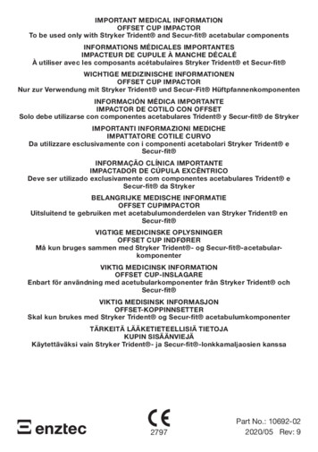
OperationsSINGLE-TOP WITH OR WITHOUT OPTIONAL VANITY OPERATIONABTo operate the table:1. Pull up on the table top to raise it.2. To unlock and lower the table top, squeeze handle (A) while guiding the table top down.3. Pull out the optional vanity (B) with the flip up mirror in either direction (if equipped).WARNINGDo not lean on table. Leaning on table may cause the table to tip which may result in injury to the individual or damageto the unit.Return To Table of Contentswww.stryker.com3150-009-001 REV B7
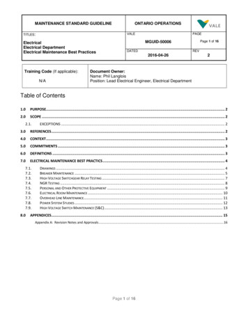
OperationsSPLIT-TOP WITH OPTIONAL VANITY OPERATIONBBB(behind mirror)CABTo operate the table:1. Pull up on the table top to raise it.2. To unlock and lower the table top, squeeze handle (A) while guiding the table top down.3. Grasp and pull any of the four handles (B) to slide out the secondary top in either direction.4. Pull out the vanity (C) with the flip up mirror in either direction.WARNINGDo not lean on table. Leaning on table may cause the table to tip which may result in injury to the individual or damageto the unit.Return To Table of Contents83150-009-001 REV Bwww.stryker.com
OperationsCLIP OPERATIONTo connect a bag to the bag clip:1. Push the clip back.2. Insert the waste bag.3. Release the clip.WARNINGDo not lean on table. Leaning on table may cause the table to tip which may result in injury to the individual or damageto the unit.Return To Table of Contentswww.stryker.com3150-009-001 REV B9
OperationsBIN OPERATIONTo operate the bin:1. Pull bin out to access storage.2. Push bin in to close.WARNINGDo not lean on table. Leaning on table may cause the table to tip which may result in injury to the individual or damageto the unit.Return To Table of Contents103150-009-001 REV Bwww.stryker.com
Preventative MaintenanceCHECKLISTAll fasteners secure.Top and laminate intact - not damaged.Top edge mold intact - not damaged.Release handle locking and releasing properly.All casters secure and swiveling properly.No debris in casters.Base cover intact - not damaged.Optional pull-out vanity and mirror intact and secure.Optional Storage Compartment intact - not damaged.CAUTIONDo not apply lubricant of any kind to the gas spring. Lubricant will damage the gas spring.Overbed Table Serial Number:Completed by:Date:CleaningThe Center for Disease Control recommends a 1:4 mixture of bleach and water for disinfection. Thoroughly rinse thesolution from the product surface. If other hospital-grade cleaning agents are used, follow the instructions provided bythe cleaning solution’s manufacturer. Wipe the surface with a soft, dry cloth to remove any moisture.As part of routine maintenance, follow steps 1-5 of the upper column replacement procedure on page 15 to removethe top assembly from the base assembly. Use a soft cloth to remove dust and debris from the top weldment tube andthe inside of the base column. Spray the top weldment tube with pure silicone spray before reassembly. DO NOT useWD-40 or any other lubricant or damage to the table could occur.Return To Table of Contentswww.stryker.com3150-009-001 REV B11
Troubleshooting GuideIdentify the problem from the table below and follow the instructions for resolution. If assistance is needed at any timeduring troubleshooting, please contact a service technician at 1-800-327-0770 option 2.Problem / FailureRecommended ActionTable drifts up.Make sure original table top and storage compartment(if applicable) remain attached to the base. If so, thenreplace the gas spring (see page 15).Table drifts down without weight on table top.If the table is difficult to raise and drops back downwhen released, replace the gas spring (see page 15).Table has a spongy feeling.This is normal as long as long as it does not drift down.Table drifts down with weight on table top.Adjust the gas spring lock pin for more clearance sothere is a little play in the handle.Table randomly drifts down withlight weight load applied.Replace gas spring (see page 15).Squeaky noise in between base and column.Add 1/4” washers under the four main base bolts.NOTE: Remove and reinstall bolts one at a time.Return To Table of Contents123150-009-001 REV Bwww.stryker.com
Service InformationOPTIONAL STORAGE COMPARTMENT REPLACEMENTTools Required: T25 Torx DriverT27 Torx DriverRegular ScrewdriverUpper ColumnClampProcedure:1. Raise the table to its full height.2. Remove the upper column cover by pullingoutward slightly on both sides and pulling outand down.3. Using a regular screwdriver, unlock the lock tabsand remove the upper column clamp.4. Using a T25 Torx driver, remove the T25 Torxscrew from the top front of the upper column.Upper Column5. Using a T27 Torx driver, remove the two screwsCoverthat hold the storage weldment to the upperweldment.6. Remove the storage compartment.7. Reverse this procedure to reinstall the storage compartment.PRIMARY TOP REPLACEMENT (SINGLE-TOP AND SINGLE-TOP WITH VANITY ONLY)Tools Required: #2 Phillips ScrewdriverWARNINGTo avoid personal injury or damage to the table, support the table top before removing the screws securing it to the topsupport.Procedure:1. If your unit has a storage compartment, follow the procedures above for Storage Compartment Replacement, thenproceed to step 2.2. Lift the table to its highest height.3. Using a Phillips screwdriver, remove the four #2 Phillips screws under the table top that hold the top to the supportweldment.4. Lift off the table top.5. If your unit has a vanity tray installed, follow steps 5a through 5c. If not, proceed to step 6.a. Turn the table top over.b. Using a Phillips screwdriver, remove the ten #10 Phillips screws that hold the vanity tracks to the bottomof the table top.c. Remove the vanity tray from the table top.6. Reverse procedures to install the new top.Return To Table of Contentswww.stryker.com3150-009-001 REV B13
Service InformationPRIMARY TOP REPLACEMENT (SPLIT-TOP WITH VANITY ONLY)Tools Required: #2 Phillips Screwdriver 3/8” Nut DriverWARNINGTo avoid personal injury or damage to the table, support the table top before removing the screws securing it to the topsupport.Procedure:1. If your unit has a storage compartment, follow the procedures on page 13 for Storage Compartment Replacement,then proceed to step 2.2. Lift the table to its highest height.3. Using a 3/8” nut driver, remove the 3/8” acorn nuts from the bottom of the table at each of the four corners.4. Lift off the table top.WARNINGTo avoid personal injury or damage to the table, while turning the table top over, securely hold the top on the sides toprevent the primary and secondary tops from separating.5.6.7.Turn the table top upside down and separate the primary and secondary tops.Using a Phillips screwdriver, remove the six #10 Phillips screws that hold the two slides on the primary table topand set them aside.Reverse procedures to install the new top.SECONDARY TOP REPLACEMENT (SPLIT-TOP ONLY)Tools Required: 3/8” Nut DriverWARNINGTo avoid personal injury or damage to the table: Support the table top before removing the screws securing it to the top support. While turning the table top over, securely hold the top on the sides to prevent the primary and secondary topsfrom separating.Procedure:1. If your unit has a storage compartment, follow the procedures on page 13 for Storage Compartment Replacement,then proceed to step 2.2. Using a 3/8” nut driver, remove the 3/8” acorn nuts from the bottom of the table at each of the four corners.3. Lift off the table top.4. Turn the table top upside down and separate the primary and secondary tops.5. Turn over the secondary top, turn the vanity tray approximately 45 degrees and remove it from the table top.6. Reverse procedures to install the new top.Return To Table of Contents143150-009-001 REV Bwww.stryker.com
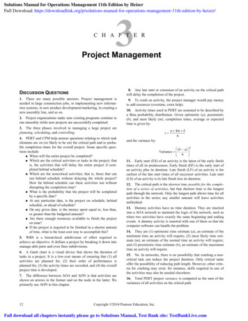
Service InformationUPPER COLUMN REPLACEMENTTools Required: #2 Phillips Screwdriver T25 Torx Driver T27 Torx DriverProcedure:1. If your unit has a storage compartment, follow the procedures on page 13 for Storage Compartment Replacement,then proceed to step 2.2. Using a T25 Torx driver, remove the three T25 Torx screws from the top of the upper column and lower the columndown to the base.3. Using a T27 Torx driver, remove the two opposing T27 Torx screws that connect the upper bushing to the lowercolumn.4. Lift the top assembly straight up and out of the lower column and set it aside.5. Reverse procedures to reassemble.GAS SPRING REPLACEMENTTools Required: T25 Torx Driver T27 Torx Driver PliersProcedure:1. If your unit has a storage compartment, follow the procedures on page 13 for Storage Compartment Replacement,then proceed to step 2.2. Using a T25 Torx driver, remove the three T25 Torx screws from the top of the upper column.3. Lower the column down to the base.4. Using a T27 Torx driver, remove the two opposing T27 Torx screws that connect the upper bushing to the lowercolumn.5. Using pliers, remove the gas spring release lever (as shown)from the gas cylinder. Gently push down on the lever and pullit out while moving it slightly from side to side.6. Lift the top assembly out of the lower column and set it aside.Gas SpringRelease Lever7. Remove the rue clip from the clevis pin that holds the gasspring assembly to the top weldment and remove the clevispin.8. Reverse to install the new gas spring.NOTES:When reinstalling the gas cylinder, align the threaded studwith the hole in the bottom of the lower column beforeplacing the top assembly above the lower column.When reinstalling the upper bushing, compress the gasspring slightly before tightening the two T27 Torx screwsthat connect the upper bushing to the lower column.Gas Spring Release Lever RemovalReturn To Table of Contentswww.stryker.com3150-009-001 REV B15
Service InformationCASTER ASSEMBLY REPLACEMENTTools Required: Cordless Drill, 3/16” Drill Bit Pop Rivet Gun with 3/16” TipProcedure:1.2.3.4.Fully raise the table top.While maintaining a secure grip on the table, carefully flip it forward or turn it on its side
2015/08 B.0 3150-009-001 REV B www.stryker.com Tru-Fit Overbed