Transcription
32 CHANNEL64 CHANNEL NVRUser ManualSRN-6450(B5)국 영.indd 6SRN-6450/3250SNR-6400/32002011-04-04 오후 3:05:43
32 Channel/64 Channel NVRUser ManualCopyright 2011 Samsung Techwin Co., Ltd. All rights reserved.Trademarkis the registered logo of Samsung Techwin Co., Ltd.The name of this product is the registered trademark of Samsung Techwin Co., Ltd.Other trademarks mentioned in this manual are the registered trademark of their respective company.RestrictionSamsung Techwin Co., Ltd shall reserve the copyright of this document. Under no circumstances, thisdocument shall be reproduced, distributed or changed, partially or wholly, without formal authorization ofSamsung Techwin.DisclaimerSamsung Techwin makes the best to verify the integrity and correctness of the contents in this document, butno formal guarantee shall be provided. Use of this document and the subsequent results shall be entirely onthe user’s own responsibility. Samsung Techwin reserves the right to change the contents of this documentwithout prior notice.WarrantyIf the product does not operate properly in normal conditions, please let us know. Samsung Techwin will resolvethe problem for free of charge. The warranty period is 3 years. However, the followings are excluded: Data loss due to a damaged hard disk If the system behaves abnormally because you run a program irrelevant to the system operation. Data loss due to virus infection Deteriorated performance or natural worn-out in process of time Sensory phenomenon that does not affect the performance or quality of the product (ex: working noise).SRN-6450(B5)국 영.indd 72011-04-04 오후 3:05:43
PrefaceThank you for choosing a Samsung Network Video Recorder (Disk Player) product.This instruction manual provides detailed information and instructions for the NVR networkDVR products. Please read this manual and any supplementary document(s) thoroughlybefore attempting to install and/or operate the product.The contents of this manual, and the software and hardware explained herein, are protected bycopyright law. All copy, reprint and translation to other languages of a part of or all of thecontents of this instruction manual without permission of Samsung Techwin Co., Ltd. areexpressly prohibited except for fair use within the scope of copyright law.The specifications of the product may change without prior notice for product improvement.Product Warranty and Limited LiabilityThe manufacturer of this product is not responsible for the sale of the product, nor does themanufacturer delegate such responsibility to a third party. The product warranty does notextend to any accident, neglect, alteration, or misuse of the product. Furthermore, thiswarranty does not cover any components or parts that are not supplied by the manufacturer ofthis product.The product warranty period is for three years from the purchase date. However, the warrantydoes not cover any of the following problems, and a nominal service fee will be charged if:z Product has been improperly used or handled by user.z Product has been disassembled and/or altered by user.z Product has been damaged by connecting a power supply with improper specifications.z Product has been damaged due to an "Act of God" (fire, flood, tsunami, natural disaster,etc.)z To replace expendable components: HDD, Fan, etc.(The warranty for the HDD and Fan is valid for one year from the purchase date.)This warranty covers only the product supplied with the warranty.After the warranty period (three years) has expired, a service fee will be charged for anyinspection and/or repair for the product. During the warranty period, a service fee will becharged for repair and/or inspection for the product for any problems that are not covered bythe warranty.1
This product is not an anti-theft or fire-prevention device; the manufacturer is notresponsible for any damage to property or personnel that may occur during its use.This product must be installed by skilled and experienced personnel; self-installation by theuser is prohibited. Self-installation by the user may result in fire, electrocution, and/or productmalfunctions. Please contact your local dealer for assistance with the installation of the product.The contents of this manual may change in order to accommodate upgrades in firmwareand/or software. Also, the specifications and/or design of this product may change without priornotice for product improvement.2
Table of ContentsPreface . 1Product Warranty and Limited Liability . 1Table of Contents . 3Chapter 1. Overview . 61.1. Safety Precautions . 61.2. Product Contents . 9Chapter 2. Part Names . 102.1. Front Panel . 102.2. Back Panel. 122.3. Default Settings . 132.3.1. Monitoring Page . 132.3.2. Playback Page . 132.3.3. Config Page . 142.3.4. System Page . 17Chapter 3. Installation . 183.1. Installing and Connecting Product . 183.1.1. Supplying Power and Operating the Product . 183.1.2. Configuring the Network . 183.1.3. Internal HDD . 193.1.4. External HDD . 223.1.5. Sensor . 233.1.6. Relays . 243.1.7. USB . 253.2. Connecting to the Website. 263.2.1. Connecting Cable . 263.2.2. Adding an IP Address . 263.2.3. Connecting and Changing Settings . 283
Chapter 4. Operation . 314.1. System Requirements . 314.2. Compatible Web Browsers . 314.3. Login . 324.4. Monitoring . 334.4.1. Splitting Screen and Changing Channels . 334.4.2. Video Control . 344.4.3. PTZ Control . 344.4.4. OSD Control . 354.5. Playback . 374.5.1. Time Search . 374.5.2. Event Search . 394.6. Config . 424.6.1. Status . 434.6.2. Record Setup . 444.6.3. Event Setup . 454.6.4. Camera Setup . 484.6.5. HDD Setup . 524.6.6. Network Setup . 584.6.7. Time Setup . 634.7. System . 654.7.1. Upgrade . 664.7.2. System Log . 684.7.3. User Setup . 714.7.4. Backup . 72Chapter 5. LCD Setup . 765.1. System . 775.1.1. Checking Firmware Version . 775.1.2. Turning On/Off Beep . 775.1.3. Relay Off . 785.1.4. System Update . 785.1.5. Initializing Settings . 795.1.6. HDD Check . 805.1.7. Shutting the System Down. 814
5.2. Network Setup. 825.2.1. Monitor Ethernet Port Setup . 825.2.2. Source Ethernet Port Setup . 855.2.3. Storage Ethernet Port Setup . 865.3. HDD Mode Setup. 875.4. Removing HDDs . 905.5. Formatting HDDs . 915.5.1. Formatting a Single Internal HDD . 915.5.2. Formatting All Internal HDDs . 925.5.3. Formatting a Single External HDD. 925.5.4. Formatting All External HDDs . 935.5.5. Formatting All HDDs . 94Troubleshooting. 95Product Specifications . 97Product Dimensions . 995
Chapter 1. OverviewThis digital video recorder plus disk player features HDD storage and playback capabilities for64/32-channel digital video.Setting up this recorder is easy; you may use the buttons on the front of the product, or connectto the product remotely via a network.With proven performance and reliability, the NVR is a self-sufficient video recorder as well asideal for digital video feed storage for monitoring systems of banks, apartment buildings, andpublic offices that require a high security level. Since video is stored on hard disk, there is noloss in picture quality due to repeated playback from the storage media. Further, since all videodata is stored as digital files, it is easily and quickly searchable.This high-resolution video recorder features a large storage capacity and also comes with awide variety of user-friendly features such as: Simultaneous recording and playbackcapabilities, motion detection, PTZ (pan, tilt, zoom) control, password, real-time voice datarecording, convenient access permissions setup using Key Lock, and maintenance of up to10,000 event lists and log files.1.1. Safety PrecautionsThe following information or instruction is vital for user safety; pleaseread it thoroughly to avoid serious injury or death.Warning Installing the Product3 Please check the power outlet voltage (AC 100V 240V) before you connect the powerto the outlet.3 Make sure that the product is switched off before you install it.3 To avoid the risk of electric shock and/or fire, do not install the product in a damp area.3 The product must be grounded to reduce the risk of electric shock. Using the Product3 Opening or removing the product case will expose you to the risk of electric shock; donot open or remove the case unless you are a qualified technician.6
3 To prevent electrical fire, do not connect multiple power cords to a single outlet.3 Do not place heavy objects or vessels containing water on the unit since it can causeserious malfunctions.3 Do not use this item in a location containing propane gas, gasoline, or other flammablesubstances to avoid risk of explosion or fire.3 To avoid the risk of electric shock, do not touch the power plug with moisture on yourhands.3 Make sure that no electrically conductive material enters the cooling vent.3 Do not pull on the power plug with any force; a damaged plug may cause electric shockor fire. Disassembling and Cleaning the Product3 There is a risk of malfunction, shock, or other dangers. Do not disassemble or attempt tofix or alter the product yourself.3 Do not clean the product with water, paint thinner, or other organic solvent as doing somay cause product malfunctions and/or electric shock. When cleaning the product, usea dry cloth to wipe the exterior of the device.Misuse or wrongful operation of the item may result in injury or damageto the item. It indicates caution should be observed when operating.Caution Installing the Product3 When installing the product, please leave at least 15 cm of space between the coolingvent and the wall for proper heat dissipation.3 To prevent user injury and product damage, please install the product on a level surfacewith no risk of the product falling.3 Avoid installation in an environment where the product will be exposed to heat or directsunlight; product deformation and/or damage may result.7
3 When installing the closure, take into consideration the operating temperature andhumidity of the installation environment according to the product specifications (seeAppendix). Using the Product3 Avoid shock and vibration while operating or moving the item.3 Do not move the product while it is in operation; do not expose the product to strongimpact or throw the product.3 If you wish to add a hard disk to the product, please contact your vendor; adding a nonrecommended hard disk may cause the product to function abnormally.3 Arbitrarily adding a hard disk to the product will void your product warranty.3 This product is not an anti-theft or fire-prevention device; the manufacturer is notresponsible for any damage to property or personnel that may occur.Samsung Techwin recommends the installation of a UPS (UninterruptedPower Supply) with all its recording ntatallproductmanufacturing stages to preserve the environment, and is taking anumber of steps to provide customers with more environmentallyfriendly ocreateenvironmentally friendly products, and indicates that the productsatisfies the EU RoHS Directive.8
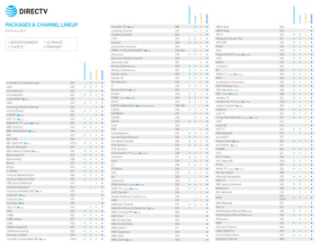
1.2. Product ContentsThe contents of this product are as shown below.Power CordKeyRack Mount and FixtureScrewsHDD Fixture ScrewsUser's ManualQuick Reference GuideCross CableHDD Tray (4EA)NET-I Viewer/User’s Manual CD9
Chapter 2. Part Names2.1. Front PanelNo.NameFunction1Key LockTurning the key completely engages the lock, so the buttons on thefront panel cannot be accessed and the HDD bay door cannot beopened.2SATA-BracketMounts hard disks for storing recorded video. Up to four hard diskscan be mounted. Mounted HDDs are referred to as Internal HDD1(upper left), Internal HDD2 (upper right), Internal HDD3 (lower left),and Internal HDD4 (lower right.)3Internal HDD1A blue indicator means that Internal HDD1 is installed andfunctioning normally. A red indicator means that Internal HDD1 is notfunctioning properly.4Internal HDD2A blue indicator means that Internal HDD2 is installed andfunctioning normally. A red indicator means that Internal HDD2 is notfunctioning properly.5Internal HDD3A blue indicator means that Internal HDD3 is installed andfunctioning normally. A red indicator means that Internal HDD3 is notfunctioning properly.6Internal HDD4A blue indicator means that Internal HDD4 is installed andfunctioning normally. A red indicator means that Internal HDD4 is notfunctioning properly.7EXTERNALHDD1A blue indicator means that an external HDD is connected to therear eSATA Port1 and functioning normally. A red indicator meansthat External HDD1 is not functioning properly.8EXTERNALHDD2A blue indicator means that an external HDD is connected to therear eSATA Port2 and functioning normally. A red indicator meansthat External HDD2 is not functioning properly.9EXTERNALHDD3A blue indicator means that an external HDD is connected to therear eSATA Port3 and functioning normally. A red indicator meansthat External HDD3 is not functioning properly.10
No.NameFunction10EXTERNALHDD4A blue indicator means that an external HDD is connected to therear eSATA Port4 and functioning normally. A red ind
Samsung Techwin. Disclaimer Samsung Techwin makes the best to verify the integrity and correctness of the contents in this document, but no formal guarantee shall be provided. Use of this document and the subsequent results shall be entirely on the user’s own responsibility. Samsung Tech