Transcription
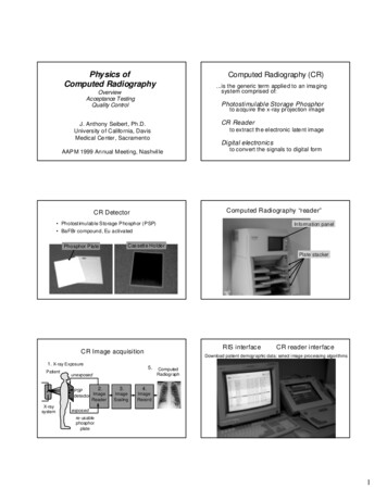
Physics ofComputed RadiographyComputed Radiography (CR).is the generic term applie d to an ima gingsystem comprised of:OverviewAcceptance TestingQuality ControlPhotostimulable Storage Phosphorto a cqu ire the x-ray pr ojection imageCR ReaderJ. Anthony Seibert, Ph .D.University o f Califo rnia, DavisMedical Ce nter , Sacramentoto extract th e el ectronic late nt imageDigital electronicsAAP M 1999 An nual Meeti ng, Nashvil leto convert the signals to digital formCR DetectorComputed Radiography “reader” Photostimulable Storage Phosphor (PSP) BaFBr compound, Eu activatedInformation panelCas sette HolderPhosphor PlatePlate stackerRIS interfaceCR Image acquisition1. X-ray ExposurePatientX-raysystem5.unexposed2.PSPdetector ImageReaderCR reader interfaceDownload patient demographic data; select image processing graphexposedre-usablephosphorplate1
ID terminal: select anatomy-specific examBar-code reader: identify exposed cassetteFilm laser printerCR NetworkingCRReader DICOM– Digital Imaging COmmunications in Medicine– Provides open architecture solutions for modalityinterfaces, storage/retrieval, and print functionsDicomCR - QC Workstation Technologist QC Workstation Modality Worklist Input Processed image outputSoft-cop y reviewCR vendorsCR Trends Fuji .(GE, Siemens, Philips, others ) Lower system costs Agfa .(Toshiba) Smaller footprint Kodak High throughput sy stems Konica Low throughput systems “Table-top” units Lumisys Integrated QC workstations for images Others DICOM output2
Digital x-ray detectorConventional film/screen detector1. A cqu isition, Display, Ar chiving1. A cqu isitionTransmitted x-raysthrough patient2. DisplayTransmitted x-raysthrough patientFilm processing:Digitalprocessinglight to optical densityGray Scaleencoded onfilmIntensifyingScreensx-rays lightFilmAn al og to Di gi talC on ve rsio n3. A rchi vingStimulation and Emission SpectraElectrons trapped in proportion to x-rays absorbed3.0 eVe-F/ F τ EuEu3 / Eu 2 Incident x-rayse-e-Laserstimulation2.0 eV8.3 eVValence bandF centers proportional toincident x-ray intensityRelative intensityPSLτ recombinationDi od e68 0 nm0.080 0He Ne63 3 nm70 01.560 01.75250 02.5λ (n m)40 030 034 Ene rgy (eV)CR: Latent Image ReadoutReferen cedetectorLight guideEmi ssion0.5Photostimulated LuminescenceIncident Laser BeamBaFBr: Eu2 Stimu latio n1.0Conduction bandτtunneling X-ray converterx-rays electronsChargecollectiondevicePSP Latent Image Formationph on onD ig ital to An al ogC on ve rsio nDigital PixelMatrixPSLSignalPMTf-θle nsLase rSourcePolyg onalMirrorCyli ndrica l mi rrorLi ght cha nnel ing gu ideOutput imulatedLuminescenceProtective LayerLaser beam:Sca n directionTo i mageproce sso rPhosphor LayerLas er Light Spr ead"Effective " read out di amete rBase SupportPMTPlat e translation:Sub-scan direction3
Phosphor Plate CyclePSPBase supportx-ray exposureSub -scan Directionplate exposure:create latent imagePlate translationreuselaser beam scanTypic al resolution:plate readout:extract latent image35 x 43 cm -- 2.5 lp/mm24 x 30 cm -- 3.3 lp/mm18 x 24 cm -- 5.0 lp/mmlight erasureplate erasure:remove residualsScan DirectionLaser beam deflectionCharacteristic Curve:CR Image Manipulationresponse of screen/film and CR Contrast enhancement– Anatomy specific grayscale manipulation Spatial frequency enhancementFinding the Image Location Image recognition phase10 ,0 004Film Optical D ensity– Find the pertinent image information– Scale the data to appropriate rangeFilm -screen(40 0 spe ed)3CR pla te1,00 0Ove rexposed210 0Corre ctly expo se d101Und erexpose d00.010.111010 01Exp osure , mR20 00 020 0020 0202Sen sitivi ty (S)Rel ative intensi ty of PSL Image pre-processingCollimation area(s) determinedCollimationBorder– collimation (Agfa)– EDR (Fuji)– segmentation (Kodak) Finding collimation borders and edges4
Processing the ImageHistogram analysis Contrast enhancement Frequenc y distribution of pixel values within adefined area in the image– MUSIC A (Agfa)– Gradation (Fuji)– Tonescaling (Kodak) Shape is anatomy specific Define dynamic range (histogram analysis) Sets minimum and maximum “useful” pixel values Transform to anatomy specific contrastData conversionHistogram DistributionOpenareaFrequencyPixel valueUseful signalInput to outpu t dig ita l number1,000Re la ti ve PSLAnatomyOutput dig ital numberCollimatedareaGrayscale transformationExposure into digital number10210110010-110-1 100 101 102 103 05111023Exp osure inputRaw Digital Outp ut8006004002000200600 1,000Raw Input d igital numbe rHistogrammi nThe shape is dependent on radiographic study,positioning and techniquemax1. Find thesignal2. Scale torange3. Create filmlook-alikeHistogram: pediatric imageto 9 368to 8 323Frequency80060040020000200400600800100 0Useful image range for anatomyDi gital valu ePre-processed nowindow/levelContrast enhanced5
Data conversion for overexposureData conversion for wide latitudeExposure into digital numberExposure into digital numberIncre ase gr adi ent1 021 02Rel ative PSLRe la ti ve PSLRe du ce gai n1 011 001 0- 1Exposurein put10 -1 10 0 10 1 10 2 10 3051 110 23Ra w Di gital Ou tp utoverexposureminmax(sca led a nd l og am pli fi ed)1 011 001 0- 1Exposurein put10 -1 10 0 10 1 10 2 10 3high kVp(w ide latitude)80 kVp, 18 mAs400 speed screen - film10 23(sca led a nd l og am pli fi ed)minmaxComputed RadiographyOverexposedScreen- Film80 kVp, 18 mAs51 1Ra w Di gital Ou tp utScreen-F ilmUnderexposed0UnderexposedOverexposedCR80 kVp, 18 mAsL 4, wide latitude6
CR: Contrast EnhancementLook-up-table transformationOutput digital number1,000MLEA800Fuji System600Example LUTs400200002004006001,000800Input digital number“Raw data”Spatial Frequency Processing“Contrast Enhanc ed”CR: Image manipulation “Edge Enhancement”Di fference :Edge Enh anced:Dash : l ow pass fi lteredOri gin al - filteredDi fference Origin alResponseSoli d: orig inal resp onseSumlo whi ghlo whi ghlo whi ghSpatial frequency“Black Bone”CR: Dual Energy ImagingLow Energy ImageHigh Energy Image“Edge Enhanced”CR: Dual Energy Imaging“Tissue only” Image“Bone only” Image7
CR: Spatial ResolutionImage Performance Measures Pho sph or p late sizes: impact on resolution Spatial res olution– Dependent on IP size– Less than corresponding speed screen-film Contrast sensitivity– Dependent on exposure and SNR Exposure– Variable speed detector35x43 (14x17)24x30 (10x12)18x24 (8x10)0.2 mm pixels0.14 mm pixels0.1 mm pixelsHigh Contrast (Spatial) Resolution18 x 24 cmMTF Curves35 x 43 cm1.00.8Pre-sampled MT FMTFScreen-filmScan0.6SubscanHi res CR0.4Sampled MT F:Standard CR2K x 2K matrix35 x 43 cmStandard CR0.20Photon absorption fraction10Low Contrast Response: Leeds TO -16X-ray Absorption Efficiency12468Spatial F requency (lp/mm)BaFBr, 100 mg/cm²0.8Gd 2O2S, 120 mg/cm 20.60.4BaFBr, 50 mg/cm²0.20020406080Energy (keV)1001201403.5 mR70 kVp0.5 mR8
Image retake ratesRetake rate evaluation -- 1st half, 19927Screen-Fil m6Wrong exam5%Motion6%CR54Positioning46%Reprinting9%3Under exposure10%210JanFebMarAprMayO verexposure12%JunTotal # repeats 1043from Willis, RSNA 1996Adu lt portable chest ca lcu lated exposuresAdu lt portable chest ca lcu lated exposuresFirst half, 1994, 4572 examsSecond half, 1994, 4661 exams38.3%60 05 3.9 %7.8%Targetexpo surerang e60 050 07 3.5 %3.4%Targetexpo surerang e50 040 0 5010 020 0030 010 0040 010 050 0Q420 0System speed (S #)LowIncident Exposure 5020 0Q330 010 0Q220 030 030 0Q140 040 0#exams#exams23.1%50 0Percent errorRepeatedExaminations with CROther12%System speed (S #)HighLowIncident ExposureHighGuidelines for QC based on Exposure,typical adult examApri l 1 - 17, 1996Adul t Po rtabl e Ch estSys tem s peed16014012010080Grid tec hniquewithout a grid6040060000-650 9 90549400435 4 90330 7 40324250220 7 40215 2 4017410012450-74200 1Number of examinations“Exposure Creep”180Sensitivi ty numberIndication 1000 0.2 mR Underexposed: repeat 600 - 10000.3-0.2 mR Underexposed: QC exception 300 - 6001.0-0.3 mR Underexposed: QC review 150 - 3001.3-1.0 mR Acceptable range 75 -1501.3-2.7 mR Overexposed: QC review 50 - 744.0-2.7 mR Overexposed: QC exception 50 4.0 mR Overexposed: repeat9
New issues for the Medical Physicist:Digital Projection ImagingRadiation Dose for CR Variable Speed Detector Differences between screen-film and PSP detectors Optimal dos e 2X higher than 400 speed screen/film– Lower absorption efficiency Testing digital systems: vendor specific details Indirect (CR) vs. direct (Flat-panel) detectors– Quantum and electronic noise Exposure levels and SNR measurements– Readout inefficiencies of latent image QC phantoms Anti-scatter grids needed Soft-copy displays and workstationsUniformityRecommended acceptance tests(Ta sk Group #10 -- AAPM)498508537480 Physical Ins pection - Inventory Evaluation of image process ing parameters490513 Imaging Plate Uniformity and Dark Noise Signal Response– Linearity and Slope– Calibration and Beam Quality497505544487 Laser Beam FunctionCR Parameter SettingsDemographics on Fuji CR outputFu ji CR reader systemEx po su re m e nu c odeR ea d out (ED R) m odeA - Auto m a ticS - S e m i-a utom a t icF - Fix e dU CD MC RA DIO LO G Y00A 0200TopoffilmFilm Imag eD ATEPO R TAB LE C HE STL 2 .0 S 2 5 0 C *1 .6 , *1 .0G 1 .0 E # 1 .0 -- 0 .2 0 R 0 .3A 054# 9 5 0 3 3 10 5 41 1 :4 5B ottom2 /3offilmL La tit ude (us e ful r an ge of e x pos ur es in o rde rs of m a gnitude )S S e ns itiv ity (v a lue inv e rs e ly re la te d to inc ide nt e x pos ur e )C De ns ity / c ontr a s t s e tting m od ific a tionsG Film ga m m a c ur ve s e tt ings (c ontr a st e nha nc e m e nt pa r am et e rs )No te : the a s s oc ia te d le tte r s in dic a te the LU T ty peR Fre que nc y pr oc e s sin g (s pa tia l a nd e dge e nh an c em en t pa ra m e te r s )A Num be r of film s s inc e la s t re bo ot of s y s te m2 /3 Im a ge re duc t ion fa c tor ( 6 7 % of a c tua l s iz e in this c a s e )R mI a ge re v e rs a l indic a torTim e0 3 .3 1 .1 9 95Pa tie nt Ide ntific a tionRAnatomical regionGener al ch est (LAT)Gener al ch est (PA)Port Chest GRIDPort Chest NO GRI DPeds chest NICU/PICUFingerWristFor earmPlaste r cast (ar m)Elbo w*Upper Ribs*Pelvis*Pelvis por tableTib/F biFoo tFoo t*Os CalcisFoo t castC-spineT- sp ni eSwimme rsLumba r spineBreast 60.60.60.60.61.80.90.90.6GS-0.2-0.5-0.0 5-0.1 5-0.20.30.20.30.40.40.00.20.20.250.3-0.0 50.40.50.5-0.0 50.50.51.00.50.50.20.51.01.010
Da te:7/1 0/98M ed ci al Phy si ci st: Antho ny Sei be rt, Ph.D.Lo ca tio n:Sy ste m Ide ntif i ca tio n:UCDM C, ACC, 3CRu ni t 3UC Da vi s Me dica l C ente rRecommended acceptance testsCR R eader and ScreensSig na l Resp on se: Calib r atio n a nd Beam Qu ality(Ta sk Group #10 -- AAPM)No te: Use mAs va ul es to pro vid e a n ap pro xi ma te ex po su re of 1 mR to th e IP.Men u TESTIP T yp e: ST 1 4x 17IP SN:Ex po su re Co n ditio nsSu bMenu A ve 2. 0L 2 , E D R se miFoc al sp ot1. 2 m mTim e del ay 2m niS ID (c m)140mR -IPSS 1( mR )ODNA0 .9 10 .9 11 21 .0 01 08 .0 011 0. 5 998 .7 11 .4 11 .3 8NANA11 3. 0 414 .3 31 .4 50 .0 7NANA High Contrast ResolutionSMD (cm)1 30k Vp De p en d en cyk VpF li trati onm AsmR -mete r801 A /l 0 .5 Cu1 A /l 0 .5 Cu15 . 004 .51 . 061 . 0611 51 A /l 0 .5 Cu1. 131 . 14600 .9 81 15 .0 0Ma xi mu m Dif f eren ce : Noise / Low-Contrast Response DistortionF i l trati o n D e pe n d en cyk VpF li trati onm As80n on e0. 50m R-me ter0 . 9680801 A /l 0 .5 Cu1A /l 2 .5 Cu4. 5060 . 001 . 060 . 99mR -IPSS 1( mR )ODNA0 .8 31 87 .0 015 4. 7 91 .4 0NA0 .9 10 .8 51 08 .0 01 24 .0 098 .7 110 5. 8 51 .3 81 .4 0NANA56 .0 80 .0 2NAMa xi mu m Dif f eren ce :12 0. 00 Erasure Thoroughness Anti-aliasing180 0. 0160 .0 010 0. 00 Positioning and collimation errors140 0. 0120 .0 0Re spon seR es po ns e8 0. 00100 .0 080 .0 06 0. 004 0. 00 Throughput60 0. 040 .0 02 0. 00S (1mR)507090kV p110S (1mR )20 .0 00. 0013 00.0 0n one1 A /l 0. 5 CuFi l trati on1Al / 2. 5CuDate:7/10/98Medical P hysicist: A nthony S eibert, P h.D.Location:Syst em Identification:UCDM C, A CC, 3CR unit 3UC Da vis Me dic al Cente rC R R eader and ScreensIn sp ection Resu lts Su mmaryAcceptable1. Physica l Inspe ction - In vento ry2. Imag ing Pla te Unif orm ity a nd Dar k No ise3.4.5.6.7.8.9.10.11.12.Sig nal Respo nse: L inea rity and Slo peSig nal Respo nse: C ali bra tion and Be am Qu alityLaser Be am Fun ctionHig h-C ontr ast R esolu tionNoi se /Low -Co ntr ast Re sp onseDisto rtio nEra su re Thor ou ghne ssAnt i-A liasingPosit ionin g an d C olli mati on E rr orsThr oug hputYe sYe sYe sYe sYe sYe sYe sYe sY es*Ye sYe sYe sCom men ts:10 mAs20 mAsSprea dsheet from Ehsan Samei, Ph.D ., Med ical Un iversity o f South Caroli naQuality ControlThree levels of system performance for quality control andsystem maintenance1. Routine: Technologist level- no radiation measurements2. Full inspection: Physicist level- radiation measurements; non-invasive adjustments3. System adjustment: Vendor service level- hardware and software maintenancePeriodic Quality Control Daily (technologist)––––General inspectionFilm processor / Laser printerErase imaging platesVerify digital interfaces and network transmission Weekly (technologist)– Verify CRT calibration– Test phantom images– System cleanliness11
Periodic Quality Control Monthly (Technologist)– Film processor maintenance (if any)– Inspect and clean image receptorsPeriodic Quality Control Semi-Annually / Annually (Physicist)– Evaluate image quality– Acceptance tests to re-establish baseline values– Review– Review film retake rate– QC review for “out-of-tolerance” issuesCR: Specifications Phosphor plate throughput Spatial res olution Contrast resolution and dynamic range patie nt expo sure tren dsretake activityQC re co rdsService hi storyCR: Clinical Considerations Sensitiv ity to scatter Multiple images per phosphor plate? Patient demographic data RIS-HIS-DICOM interfaces / compliance Image quality control Peripheral equipment; QC phantoms Input to PACS Service issues; plate longevity; warrantiesComputed Radiography Experience Flexibility is a double-edged sword– reduced retakes but higher under/over exposures– variable speed (need to tailor exposure to exam)– more difficult to correctly useSummary CR is currently the only readily available technologyfor direc t digital acquisition of projection radiographs Experience with CR will provide a framework forfuture digital detector implementation and QC Provides guidelines for new digital detectors Indicates the need for continuous training Filmless radiology requires a lot more than just digitalacquisition devices -- a massive investment in PACSand knowledgeable support personnel, includingMEDICAL PHYSICIST INPUT is necessary12
Light Scattering Laser Light Spread Photostimulated Luminescence "Effective" readout diameter Exposed Imaging Plate Light guide PSL Signal CR: Latent Image Readout PMT Polygonal Mirror Laser Source Light channeling guide Plate translation: Sub-scan direction Laser beam: Scan direction Ou