Transcription
Title:Product:Access Control System Installation GuideAccess controller , Access control terminalVersion:v1.0Date:Page:09/24/20181 of 15Access Control System Installation GuideCables and Wiring The line pipe (trunk channel) has open lines and buried lines. The open line requires horizontal and vertical, neatand beautiful, and the buried lines require short, smooth and less elbows; Follow the shortest route, do not destroy the original strong electricity, do not damage the waterproof principle, allthe lines must be laid in a straight line All the wires should be installed in pipe, do not lay bare wires, and there should be no connectors in the middle ofcommunication and network cables; All cables must be installed in correct place, better to prepare extra length (1.5m-2.0m), the lines must be clearlymarked, so we can distinguish and connect correct cable between devices. Install high voltage and low current cables in same slot is prohibited, remember to separate the cables and thedistance between two types cable should be more than 0.5 meters; For wiegand card reader, it’s recommended to use RVVP 4*1.0 (2 cores for power, 2 for data transmission), ifrequest feedback for reader LED light and beeper sound when swipe legal or illegal card, then we have to use RVVP8*1.0, the distance between device and reader should be less than 80 meters For exit button we can use RVV2*0.5。Network cable should be CAT5E or higher. For RS485 reader, it’s recommended to use RVVP 4*1.0, and the distance between device and reader should be lessthan 800 meters. For lock, the cable is RVV6*1.0 (4 cores for lock, 2 reserved), if the power output from device to lock is much lessthan 12V, it’s better to use separate power adapter for lock.Device Installation Access control device should be installed in the metal box, the box should be built more than 50 cm far from heavyelectricity, lamps, air conditioners, heat sources, water and other interference equipment and do a good groundingmeasure, a spacious space is required to facilitate the work; If the access controller is placed on site, it is recommended to install the field control box on the ceiling of the room,close to the manhole Common reader mounting gang box size: 86 gang box for 86 mm*86mm, 120 gang box for 120 mm*74mm It is recommended to use a non-switched linear DC power supply as the reader power source to ensure optimalsensing distance. When the device and the electric lock distance is more than 100 meters, it is recommended to usea separate power supply, the lock and device power supply should common grounding In order to ensure the normal status of the reader, input power should be 12v 10%, the distance between twocard reader should be at least 30 cm or more; Hangzhou Hikvision Digital Technology Co.,Ltd. All Rights Reserved.No.555 Qianmo Road, Binjiang District, Hangzhou 310052, China Tel: 86-571-8807-5998 Fax: 1 909-595-0788E-Mail: support@hikvision.com www.hikvision.com
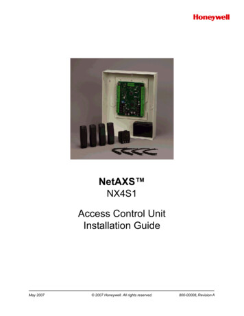
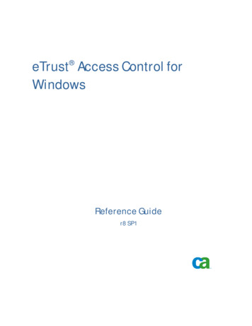
Title:Product: Access Control System Installation GuideAccess controller , Access control terminalVersion:v1.0Date:Page:09/24/20182 of 15The reader sensing distance is susceptible to metal and other materials, if installed on metal materials, it’srecommended to install appropriate thickness of the plastic gasket at the back of card reader; In order to ensure the long-term use of devices, better to install the card reader in the rain and sun protectionenvironment, if install outside better to do a good anti-rain measures, such as the acrylic cover and do waterproofsilicone treatment.Access Control System StructureNote: The specific wiring and terminal definition if it is different from the site terminal (considering the devicecustomization and upgrade, etc.), please refer to the device user manual.1. Common access control system structureCentral ServerManagement CenterDesktop ServerMultiple ClientFP Issuer Card IssuerLANWAN(byTCP/IPController System ardReaderLockExit Button Hangzhou Hikvision Digital Technology Co.,Ltd. All Rights Reserved.No.555 Qianmo Road, Binjiang District, Hangzhou 310052, China Tel: 86-571-8807-5998 Fax: 1 909-595-0788E-Mail: support@hikvision.com www.hikvision.comRVV
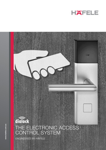
Title:Product: Access Control System Installation GuideAccess controller , Access control terminalVersion:v1.0Date:Page:09/24/20183 of 15Recommended structure: Access controller communicate with server/PC via TCP/IP protocol; access controllercommunicate with card reader through RS485 protocol. For access control point, normally we have single and dual direction, for single direction is to swipe card forentrance and press exit button for exit, dual direction is swiping card for both direction.2. Access control system sample installationTake two door single direction access control point for example Card Reader, exit button are generally installed in the height of 1.3m from the ground, the electric lock installed inthe middle of the door frame, note that the iron block installed on the doors should be aligned with the electricallock, or the electric lock indicator will show errors. Cable generally installed on the ceiling and in the pipe3. Device wiring3.1 Access controller connect to DS-K1100 series RS485 readerTwo-core power cable of the card reader is PWR (red), GND (black) respectively connected to the accesscontroller on the 12v, GND, two-core signal cable RS485 (yellow), RS485-(blue) respectively connect to thecontroller of the RS485 , RS485-. If there are multiple RS485 readers, connect all of them to these four ports. Hangzhou Hikvision Digital Technology Co.,Ltd. All Rights Reserved.No.555 Qianmo Road, Binjiang District, Hangzhou 310052, China Tel: 86-571-8807-5998 Fax: 1 909-595-0788E-Mail: support@hikvision.com www.hikvision.com
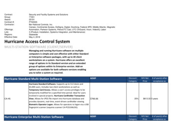
Title:Product:Access Control System Installation GuideAccess controller , Access control terminalVersion:v1.0Date:Page:09/24/20184 of 15Each reader should have a unique dial code for dip switch, Dial code 1, 2 corresponds to the door 1 of theentrance and exit, dial 3, 4 corresponding to the door 2 entrance and exit, etc. Wiegand card readerCard reader's two-core power line PWR (red), GND (black) connect to the access controller 12v, GND, fivecore signal line W0 (green), W1 (white), Beep (purple), Red led (orange), Blue led (Brown) respectively connectto the controller W0, W1, BZ, ERR, OK.Note 1:If the access controller wants to control the beep sound and led light of the card reader, OK/ERR/BZ wiresmust be connected properly, if the OK/ERR/BZ wires are not connected, device will also work withGND/PWR/W0/W1 4 cables connected, but the legal card and the illegal card cannot be identified by thereader LED color and buzzer.Note 2:DS-K2601 support maximum 2 RS485 readers and 2 Wiegand readers;DS-K2602 each door support maximum 2 RS485 card readers and 2 Wiegand readers, in total support 4 RS485card readers and 4 Wiegand card reader;DS-K2604 each door support maximum 2 RS485 card readers and 1 Wiegand reader, in total support 8 RS485card readers and 4 Wiegand card readers. Hangzhou Hikvision Digital Technology Co.,Ltd. All Rights Reserved.No.555 Qianmo Road, Binjiang District, Hangzhou 310052, China Tel: 86-571-8807-5998 Fax: 1 909-595-0788E-Mail: support@hikvision.com www.hikvision.com
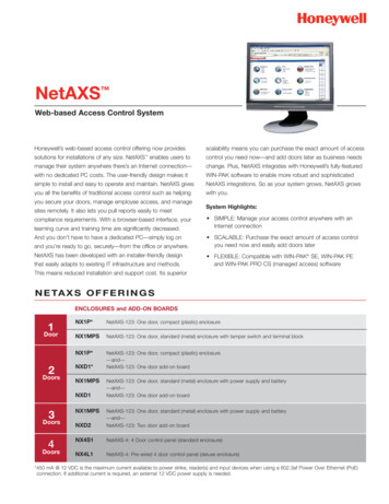
Title:Product:Access Control System Installation GuideAccess controller , Access control terminalVersion:v1.0Date:Page:09/24/20185 of 153.2 Connect to electric lockNote:Magnetic Locks: Power on Lock (suction), power off unlock, normally closed type;Positive lock (electric bolt lock): Power on lock (lock bolt eject), power off unlock (lock bolt retracted),normally closed type;Cathode Lock: Power lock, Power lock, the default is normally open type. Single door magnetic lock/Positive lockThe magnetic or positive lock two power cables(red positive black negative) are connected to the controllerLock , Lock-. Hangzhou Hikvision Digital Technology Co.,Ltd. All Rights Reserved.No.555 Qianmo Road, Binjiang District, Hangzhou 310052, China Tel: 86-571-8807-5998 Fax: 1 909-595-0788E-Mail: support@hikvision.com www.hikvision.com
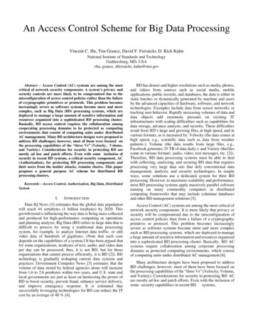
Title:Product: Access Control System Installation GuideAccess controller , Access control terminalVersion:v1.0Date:Page:09/24/20186 of 15Cathode lockThe two power cables (red positive black negative) of the cathode lock is connected to the Lock and Lock- ofthe controller.3.3 Connect to fire alarm linkageFire alarm linkage integration requirements: when the fire signal come, access control system will link dooropen automatically. There are two main types of linkage: software linkage and hardware linkage, in general,we have to use hardware linkage to achieve integration. Briefly introduce the key components under thehardware linkage mode: relay.At present, the most commonly used relays are electromagnetic relays,No (normally open) status: The status of the relay is disconnected when no powerNC (normally closed) status: The status of the relay is connected when no powerThe basic working principle of the hardware linkage is that the power supply circuit of the electric lock is cutoff by the relay, and the door is opened. Therefore, we only need to connect the fire relay to the power supplycircuit of the electric lock. Dry contact(ON/OFF) signalConnect 2 fire alarm cable direct to Fire Alarm Interface of access controller Hangzhou Hikvision Digital Technology Co.,Ltd. All Rights Reserved.No.555 Qianmo Road, Binjiang District, Hangzhou 310052, China Tel: 86-571-8807-5998 Fax: 1 909-595-0788E-Mail: support@hikvision.com www.hikvision.com
Title:Product: Access Control System Installation GuideAccess controller , Access control terminalVersion:v1.0Date:Page:09/24/20187 of 1524 voltage signalUse a relay(purchase from local market) to transfer voltage signal to Dry contact(ON/OFF) signal, then followstep above. Please select correct relay according to fire alarm system output signal voltage.3.4 Connect to door sensor Single doorCheck the label on the door for sensor cable (2 pin, please notice door sensor signal is different from lockstatus signal, we need door sensor cable), connect 2 door sensor cables to Door Magnetic and GND Double-door lockHere we have 2 types, NC wiring and NO wiring Hangzhou Hikvision Digital Technology Co.,Ltd. All Rights Reserved.No.555 Qianmo Road, Binjiang District, Hangzhou 310052, China Tel: 86-571-8807-5998 Fax: 1 909-595-0788E-Mail: support@hikvision.com www.hikvision.com
Title:Product:Access Control System Installation GuideAccess controller , Access control terminalVersion:v1.0Date:Page:09/24/20188 of 15i) NC wiringWhen any door open, upload to controller a connected signal.When two doors closed, upload to controller a disconnected signal.ii) NO wiringWhen any door open, upload to controller a disconnected signal.When two doors closed ,upload to controller a connected signal.Note 1:The door magnetic signal can feedback the status of the door, the electric lock will also work normally even doorsensor cables are not connected but unable to view the real-time door status on e-map of softwareNOTE 2:The door sensor wiring method (NO or NC) must be the same as the door sensor type on software configuration. Hangzhou Hikvision Digital Technology Co.,Ltd. All Rights Reserved.No.555 Qianmo Road, Binjiang District, Hangzhou 310052, China Tel: 86-571-8807-5998 Fax: 1 909-595-0788E-Mail: support@hikvision.com www.hikvision.com
Title:Product:Access Control System Installation GuideAccess controller , Access control terminalVersion:v1.0Date:Page:09/24/20189 of 153.5 Connect to exit button4. Lock installation Magnetic lock installation (normal)Note: When the door frame width is sufficient to install the lock body, we don’t need LZ bracket, install magnetic lockbody directly on the door frame, iron plate installed on the movable doorNote: If we install magnetic lock on glass door, we need a U bracket for fixing the iron sheet. glass door ismounted with a magnetic lock and the door can only be opened one direction. Hangzhou Hikvision Digital Technology Co.,Ltd. All Rights Reserved.No.555 Qianmo Road, Binjiang District, Hangzhou 310052, China Tel: 86-571-8807-5998 Fax: 1 909-595-0788E-Mail: support@hikvision.com www.hikvision.com
Title:Product: Access Control System Installation GuideAccess controller , Access control terminalVersion:v1.0Date:Page:09/24/201810 of 15Magnetic Lock Installation (LZ bracket)When door frame width is not enough to install lock body, we need LZ-Bracket. Positive lock (electric bolt lock)Note: The first picture is the general installation method. The second picture is the glass door without bottomframe, then use down U bracket for installation. The third picture is the glass door without upper and bottomframe, then use up and down U bracket for installation. Hangzhou Hikvision Digital Technology Co.,Ltd. All Rights Reserved.No.555 Qianmo Road, Binjiang District, Hangzhou 310052, China Tel: 86-571-8807-5998 Fax: 1 909-595-0788E-Mail: support@hikvision.com www.hikvision.com
Title:Product: Access Control System Installation GuideAccess controller , Access control terminalVersion:v1.0Date:Page:09/24/201811 of 15Cathode lockNote: The cathode lock refers to the latch that is mounted on the door frame and we do not provide amechanical lock part Hangzhou Hikvision Digital Technology Co.,Ltd. All Rights Reserved.No.555 Qianmo Road, Binjiang District, Hangzhou 310052, China Tel: 86-571-8807-5998 Fax: 1 909-595-0788E-Mail: support@hikvision.com www.hikvision.com
Title:Product:Access Control System Installation GuideAccess controller , Access control terminalVersion:v1.0Date:Page:First Choice for Security ProfessionalsHIKVISION Technical Support Hangzhou Hikvision Digital Technology Co.,Ltd. All Rights Reserved.No.555 Qianmo Road, Binjiang District, Hangzhou 310052, China Tel: 86-571-8807-59
Connect 2 fire alarm cable direct to Fire Alarm Interface of access controller Title: Access Control System Installation Guide Version: v1.0 Date: 09/24/2018 Product: