Transcription
X9DR3-LN4F X9DRi-LN4F USER’S MANUALRevision 1.0
The information in this User’s Manual has been carefully reviewed and is believed to be accurate.The vendor assumes no responsibility for any inaccuracies that may be contained in this document,and makes no commitment to update or to keep current the information in this manual, or to notifyany person or organization of the updates. Please Note: For the most up-to-date version of thismanual, please see our Website at www.supermicro.com.Super Micro Computer, Inc. ("Supermicro") reserves the right to make changes to the productdescribed in this manual at any time and without notice. This product, including software and documentation, is the property of Supermicro and/or its licensors, and is supplied only under a license.Any use or reproduction of this product is not allowed, except as expressly permitted by the termsof said license.IN NO EVENT WILL SUPER MICRO COMPUTER, INC. BE LIABLE FOR DIRECT, INDIRECT,SPECIAL, INCIDENTAL, SPECULATIVE OR CONSEQUENTIAL DAMAGES ARISING FROM THEUSE OR INABILITY TO USE THIS PRODUCT OR DOCUMENTATION, EVEN IF ADVISED OFTHE POSSIBILITY OF SUCH DAMAGES. IN PARTICULAR, SUPER MICRO COMPUTER, INC.SHALL NOT HAVE LIABILITY FOR ANY HARDWARE, SOFTWARE, OR DATA STORED OR USEDWITH THE PRODUCT, INCLUDING THE COSTS OF REPAIRING, REPLACING, INTEGRATING,INSTALLING OR RECOVERING SUCH HARDWARE, SOFTWARE, OR DATA.Any disputes arising between the manufacturer and the customer shall be governed by the laws ofSanta Clara County in the State of California, USA. The State of California, County of Santa Clarashall be the exclusive venue for the resolution of any such disputes. Supermicro's total liability forall claims will not exceed the price paid for the hardware product.FCC Statement: This equipment has been tested and found to comply with the limits for a ClassA digital device pursuant to Part 15 of the FCC Rules. These limits are designed to providereasonable protection against harmful interference when the equipment is operated in a commercialenvironment. This equipment generates, uses, and can radiate radio frequency energy and, if notinstalled and used in accordance with the manufacturer’s instruction manual, may cause harmfulinterference with radio communications. Operation of this equipment in a residential area is likelyto cause harmful interference, in which case you will be required to correct the interference at yourown expense.California Best Management Practices Regulations for Perchlorate Materials: This Perchloratewarning applies only to products containing CR (Manganese Dioxide) Lithium coin cells. “PerchlorateMaterial-special handling may apply. See ING: Handling of lead solder materials used in thisproduct may expose you to lead, a chemical known tothe State of California to cause birth defects and otherreproductive harm.Manual Revision 1.0Release Date: Feb. 22, 2012Unless you request and receive written permission from Super Micro Computer, Inc., you may notcopy any part of this document.Information in this document is subject to change without notice. Other products and companiesreferred to herein are trademarks or registered trademarks of their respective companies or markholders.Copyright 2012 by Super Micro Computer, Inc.All rights reserved.Printed in the United States of America
PrefacePrefaceThis manual is written for system integrators, PC technicians andknowledgeable PC users. It provides information for the installation and use of theX9DR3-LN4F /X9DRi-LN4F motherboard.About This MotherboardThe Super X9DR3-LN4F /X9DRi-LN4F motherboard supports dual Intel E5-2600Series (Socket R) processors that offer QPI (Intel QuickPath Interface) Technology(V.1.1), providing point-to-point connection with a transfer speed of up to 8.0 TG/s.With the C606/C602 chipset built in, the X9DR3/i-LN4F motherboard provides support for Intel Manageability Engine (ME), Rapid Storage Technology, Digital MediaInterface (DMI), PCI-E Gen. 3.0, and 1600 MHz DDR3 memory, greatly enhancingsystem performance for high end server platforms. This motherboard is ideal forHPC/Cluster/Database servers. Please refer to our Website (http://www.supermicro.com) for processor and memory support updates.Manual OrganizationChapter 1 describes the features, specifications and performance of the motherboard. It also provides detailed information about Intel C606/C602 chipset.Chapter 2 provides hardware installation instructions. Read this chapter when installing the processor, memory modules, and other hardware components into thesystem. If you encounter any problems, see Chapter 3, which describes troubleshooting procedures for video, memory, and system setup stored in the CMOS.Chapter 4 includes an introduction to the BIOS, and provides detailed informationon running the CMOS Setup utility.Appendix A provides BIOS Error Beep Codes.Appendix B lists software installation instructions.iii
X9DR3-LN4F /X9DRi-LN4F Motherboard User’s ManualConventions Used in the ManualPay special attention to the following symbols for proper system installation and toprevent damage to the system or injury to yourself:Danger/Caution: Instructions to be strictly followed to prevent catastrophicsystem failure or to avoid bodily injuryWarning: Important information given to ensure proper system installationor to prevent damage to the componentsNote: Additional information given to differentiate between various modelsor provides information for correct system setup.iv
PrefaceContacting SupermicroHeadquartersAddress:Super Micro Computer, Inc.980 Rock Ave.San Jose, CA 95131 U.S.A.Tel: 1 (408) 503-8000Fax: 1 (408) 503-8008Email:marketing@supermicro.com (General Information)support@supermicro.com (Technical per Micro Computer B.V.Het Sterrenbeeld 28, 5215 ML's-Hertogenbosch, The NetherlandsTel: 31 (0) 73-6400390Fax: 31 (0) 73-6416525Email:sales@supermicro.nl (General Information)support@supermicro.nl (Technical Support)rma@supermicro.nl (Customer Support)Asia-PacificAddress:Super Micro Computer, Inc.4F, No. 232-1, Liancheng Rd.Chung-Ho 235, Taipei CountyTaiwan, R.O.C.Tel: 886-(2) 8226-3990Fax: 886-(2) t@supermicro.com.tw (Technical Support)Tel: 886-(2) 8226-5990 (Technical Support)v
X9DR3-LN4F /X9DRi-LN4F Motherboard User’s ManualTable of ContentsPrefaceChapter 1 Overview1-1Overview. 1-11-2Processor and Chipset Overview.1-111-3Special Features. 1-121-4PC Health Monitoring. 1-121-5ACPI Features. 1-131-6Power Supply. 1-131-7Super I/O. 1-141-8Advanced Power Management. 1-141-9Overview of the Nuvoton WPCM450 Controller. 1-15Chapter 2 Installation2-1Static-Sensitive Devices. 2-1Precautions. 2-1Unpacking. 2-12-2Processor and Heatsink Installation. 2-2Installing the LGA2011 Processor . 2-2Installing a Passive CPU Heatsink. 2-6Removing the Heatsink. 2-72-3Installing and Removing the Memory Modules. 2-8Installing & Removing DIMMs. 2-8Removing Memory Modules. 2-82-4Motherboard Installation.2-11Tools Needed.2-11Location of Mounting Holes.2-11Installing the Motherboard. 2-122-5Control Panel Connectors and I/O Ports. 2-13Back Panel Connectors and I/O Ports. 2-13Back Panel I/O Port Locations and Definitions . 2-13Serial Ports. 2-14Video Connection. 2-14Universal Serial Bus (USB). 2-15Ethernet Ports. 2-16Unit Identifier Switch. 2-17Front Control Panel. 2-18Front Control Panel Pin Definitions. 2-19NMI Button. 2-19vi
Table of ContentsPower LED . 2-19HDD LED. 2-20NIC1/NIC2 LED Indicators. 2-20Overheat (OH)/Fan Fail/PWR Fail/UID LED. 2-21Power Fail LED. 2-21Reset Button . 2-22Power Button . 2-222-6Connecting Cables. 2-23Power Connectors . 2-23Fan Headers. 2-24Chassis Intrusion . 2-24Internal Speaker. 2-25Power LED/Speaker. 2-25TPM Header/Port 80. 2-26Power SMB (I2C) Connector. 2-27Overheat/Fan Fail LED. 2-27T-SGPIO 1/2 Headers. 2-28DOM Power Connector. 2-28IPMB. 2-292-7Jumper Settings. 2-30Explanation of Jumpers. 2-30GLAN Enable/Disable. 2-30CMOS Clear. 2-31Watch Dog Enable/Disable. 2-31VGA Enable. 2-32BMC Enable . 2-322-8Onboard LED Indicators. 2-33GLAN LEDs. 2-33IPMI Dedicated LAN LEDs. 2-33Onboard Power LED . 2-34Rear UID LED . 2-34BMC Heartbeat LED. 2-352-9Serial ATA Connections. 2-36Serial ATA (SATA) Ports. 2-36SCU Ports. 2-36Chapter 3 Troubleshooting3-1Troubleshooting Procedures. 3-1Before Power On. 3-1No Power. 3-1vii
X9DR3-LN4F /X9DRi-LN4F Motherboard User’s ManualNo Video. 3-2System Boot Failure . 3-2Losing the System’s Setup Configuration. 3-2Memory Errors . 3-3When the System Becomes Unstable. 3-33-2Technical Support Procedures. 3-53-3Battery Removal and Installation. 3-6Battery Removal. 3-6Proper Battery Disposal. 3-6Battery Installation. 3-63-4Frequently Asked Questions. 3-73-5Returning Merchandise for Service. 3-8Chapter 4 BIOS4-1Introduction. 4-1Starting BIOS Setup Utility. 4-1How To Change the Configuration Data. 4-1Starting the Setup Utility. 4-24-2Main Setup. 4-24-3Advanced Setup Configurations. 4-34-3Event Logs. 4-234-4IPMI. 4-254-5Boot. 4-274-6Security. 4-284-7Save & Exit. 4-29Appendix A BIOS Error Beep CodesA-1BIOS Error Beep Codes.A-1Appendix B Software Installation InstructionsB-1Installing Software Programs.B-1B-2Configuring SuperDoctor III.B-2viii
Chapter 1: OverviewChapter 1Overview1-1OverviewChecklistCongratulations on purchasing your computer motherboard from an acknowledgedleader in the industry. Supermicro boards are designed with the utmost attention todetail to provide you with the highest standards in quality and performance.Please check that the following items have all been included with your motherboard.If anything listed here is damaged or missing, contact your retailer.The following items are included in the retail box. One (1) Supermicro Mainboard Two (2) Serial ATA cables (CBL-0044Lx2) Two (2) I-Pass to 4 Serial ATA (50-cm) cables (CBL-097L-02) (for X9DR3LN4F ) One (1) I-Pass to 4 Serial ATA (50-cm) cable (CBL-097L-02) (for X9DRi-LN4F ) One (1) I/O Shield (MCP-260-00042-0N) One (1) Supermicro CD containing drivers and utilities One (1) User's/BIOS Manual (MNL#1258)1-1
X9DR3-LN4F /X9DRi-LN4F Motherboard User’s ManualMotherboard ImageNote: All graphics shown in this manual were based upon the latest PCBRevision available at the time of publishing of the manual. The motherboardyou've received may or may not look exactly the same as the graphicsshown in this manual.1-2
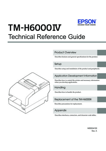
Chapter 1: OverviewMotherboard LayoutFAN6FAN5PHYP2 DIMMG1P2 DIMMG3P2 DIMMG2JTPM1JPI2C1USB9JBT1BIOS BOXJBAT1JL1JPW3JPW2P1 DIMMA1P1 DIMMB2P1 DIMMB3CPU1P1 DIMMD1P1 DIMMD2P1 DIMMC3P1 DIMMC2JPW1I-SATA0I-SATA1P1 I-SATA4JRK1 BIOSAlaways populate DIMMx1 firstP1 DIMMD3PCHJWD1JBR1XDP-PCHUSB6/7 USB4/5P1 DIMMB1P1 DIMMA3P2 DIMMH3Alaways populate DIMMx1 firstCPU2COM2FANAFANB1-3FAN11P2 DIMMF3P2 DIMMF1P2 DIMMF2P2 DIMME3P2 DIMME2P2 DIMME1CPU2 Slot6 PCI-E 3.0x8CPU2 Slot5 PCI-E 3.0 x16CPU2 Slot4 PCI-E 3.0 x16CPU1 Slot3 PCI-E 3.0 x16CPU1 Slot2 PCI-E 3.0 x4(in X8 Slot)J21JWP1P1 DIMMA2X9DR3-LN4F /X9DRi-LN4F P2 DIMMH1JI2C2JI2C1P2 DIMMH2SASCTRLRev. 1.10XDP-CPUCOM1USB 0/1USB 2/3LAN1/3LAN2/4VGALE1JF1JD1JPL1LANCTRLJPB1JP6CPU1 Slot1 PCI-E 3.0 x16JBMC1 JSTBY1JPG1J181JF2SAS0 3SAS4 7J17JP7IPMI LANBMCCTRLLEM1SW1UIDLE2Note: For the latest CPU/Memory updates, please refer to our website athttp://www.supermicro.com/products/motherboard/ for details.
X9DR3-LN4F /X9DRi-LN4F Motherboard User’s ManualX9DR3-LN4F /X9DRi-LN4F Quick ReferenceUSB 0/1COM1FAN5PHYP2 DIMMG1P1 DIMMA3P1 DIMMA2P2 DIMMG3P2 DIMMH1P2 DIMMG2P2 DIMMH2COM2CPU2P2 DIMMH3Alaways populate DIMMx1 firstP2 DIMMF3P2 DIMMF1P2 DIMMF2P2 DIMME3P2 DIMME2P2 DIMME1CPU2 Slot6 PCI-E 3.0x8JP6USB 2/3IPMI LANCPU2 Slot5 PCI-E 3.0 x16CPU2 Slot4 PCI-E 3.0 x16CPU1 Slot3 PCI-E 3.0 x16CPU1 Slot2 PCI-E 3.0 x4(in X8 Slot)J21CPU1 Slot1 PCI-E 3.0 x16JBMC1 JSTBY1JPG1JP7LAN1/3JPL1LANCTRLJ
Super Micro Computer, Inc. ("Supermicro") reserves the right to make changes to the product described in this manual at any time and without notice. This product, including software and docu-mentation, is the property of Supermicro an