Transcription
Expert Reference Series of White PapersConfiguringMulticast withMPLS andGETVPN1-800-COURSESwww.globalknowledge.com
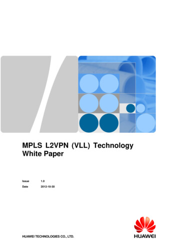
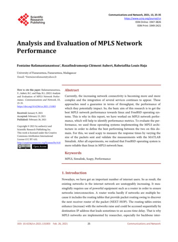
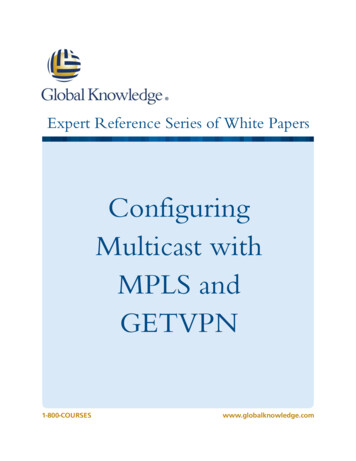
Configuring Multicast with MPLS andGETVPNBilll Treneer, CCSI, CCNP, CCDP, CWLSS, CCNA, CCDA, CompTIA Security ,and CompTIA Network IntroductionThis paper describes how to configure IP Multicast with Multiprotocol Label Switching (MPLS). Using only MPLSthe configuration will not include encryption and is described first. Next the paper will add encryption forMulticast with the Group Encrypted Transport VPN, GETVPN.The key to using MPLS for multicast is for MPLS routers inside the core use the existing Layer 3 routinginformation for multicast replication. This replication inside the MPLS core improves multicast efficiencies andnetwork performance (see Figure 1).Figure 1: Multicast Scalability of MPLS CoreWith multicast core replication a Protocol Independent Multicast (PIM) adjacency is made between the CustomerEdge (CE) and Provider Edge (PE) routers. PE routers maintain PIM adjacencies with CE routers, other PE routers,and with Provider (P) routers. No PIM adjacency is needed between CE devices not directly connected. This allowsfor a lot more scalable configuration than using CE to CE tunnels.Multicast-enabled VPNs will create a VPN multicast routing table (MVRF). To support VPN-aware multicastsystems, PIM Spare Mode, Spare Mode Bi-Directional, (Bi-Dir), or Source Specific Multicast SSM capability must beenabled on all affected P and PE routers. This addition results in a global multicast routing table being created inthe provider network routers. The PE routes that have been configured to run PIM (global instance) will establisha PIM adjacency with neighboring P routers. The MPLS core and the enterprise network connected to it haveseparate instances of multicast routing with different rendezvous points.There is no requirement to run the same multicast protocols in the customer and provider network. For example:Sparse mode in the enterprise; SSM in the MPLS Core; PIM Bi-Dir in the enterprise; and Sparse mode in the MPLSCore, etc. If PIM is configured as the CE-to-PE multicast protocol, the PE devices maintain PIM adjacencies with CEdevices. No PIM adjacency will be established between CE devices that are not directly connected.Copyright 2015 Global Knowledge Training LLC. All rights reserved.2
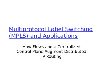
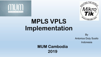
The network diagram in Figure 2 represents an MPLS carrier backbone. R1 and R5 are CE routers. The backbonehas routers R2, R3, and R4 that belong to the same VPN Routing and Forwarding (VRF) instance, which is definedas the yellow VRF. The backbone is configured to support MPLS VPN, which includes all necessary routingprotocols that are not shown in the configurations. R2 and R4 are PE routers and R3 is a P router.To provide multicast services, the backbone is enabled to run multicast routing with the global configurationcommand. PIM Sparse Mode is configured on router interfaces as the multicast routing protocol, although twovariations of sparse mode, Bi-Dir and SSM, are also good options. Legacy PIM dense mode should be avoided. R2and R4 are also configured to run multicast routing in the yellow VRF. R3 is the Rendezvous Point (RP) for VRFyellow (see Figure 2).Figure 2: Multicast configuration of first CE routerAll CE routers need to enable multicast routing globally and apply sparse mode to the physical interfaceconnected to the MPLS carrier. R1’s rendezvous point RP would be defined with the global command:ip pim rp-address rp-address [access-list] [override] [bidir]The RP’s address is not shown in this example as R1’s RP is a router on the enterprise network to its left. The CER1 would likely have a different RP than the one defined for the MPLS core. The PIM Bi-Directional command isoptional if it is running as would be SSM. Next, configure the R2 PE router in Figure 3.Copyright 2015 Global Knowledge Training LLC. All rights reserved.3
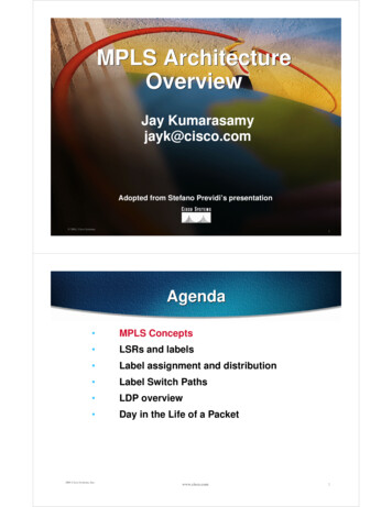
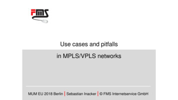
Figure 3: Multicast Configuration of first PE routerThe PE router R2’s configuration needs the following: The default Multicast Distribution Tree (MDT) for VRF yellow.The global address range for the data MDTs and the threshold at 10 kbps. Multicast streams below 10kbps stay on the default MDT and those above get a Data MTD.Enabling multicast routing globallyEnabling multicast routing in VRF yellowPIM sparse mode enabled on loopback interface 0 as it is used as a source for Multiprotocol BorderGateway Protocol, MBGP sessions between PE routers that participate in Multicast VPN, (MVPN).R3 router defined as the RP for multicast in VRF yellow.Multicast is enabled on PE-CE interfaces in the VRF, Serial 1/0.Service provider core needs to run multicast to support MVPN services, so multicast is enabled on PE-Plinks Serial 2/0.To statically configure the address of the rendezvous point (RP) for an MPLS VRF environment, use theglobal command: ip pim [ vrf vrf-name ] rp-address rp-address [access-list] [override] [bidir]PIM Bi-Dir is optional as is Source Specific Multicast, SSM.Next, configure the R3 “P” router in Figure 4.Copyright 2015 Global Knowledge Training LLC. All rights reserved.4
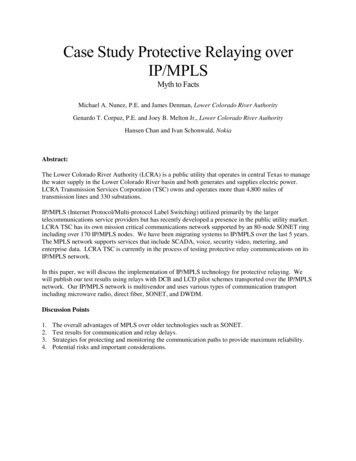
Figure 4: Multicast Configuration of “P” routerEnable PIM sparse mode on links to PE routers which have MVPNs configured. Serial 1/0 and serial 2/0 areconnected to the two PE routers. R3 recognizes its own loopback address as the RP. PIM Bi-Dir is optional as isSSM. Next, configure the R4 “PE” router in Figure 5.Copyright 2015 Global Knowledge Training LLC. All rights reserved.5
Figure 5: Multicast Configuration of second “PE” routerThe second PE router R4’s configuration needs the following: The default Multicast Distribution Tree (MDT) for VRF yellow.The global address range for the data MDTs and the threshold at 10 kbps.Enable multicast routing globally and enable multicast routing in VRF yellowPIM sparse mode enabled on loopback interface 0 as it is used as a source for MPBGP sessions betweenPE routers that participate in MVPNMulticast is enabled on PE-CE interfaces in the VRF, Serial 2/0.Service provider core needs to run multicast to support MVPN services, so multicast is enabled on PE-Plinks Serial 1/0.R3 router defined as the RP for multicast in VRF yellow. Statically configure R3 as the RP for an MPLS VRFenvironment. Use the global command: ip pim [ vrf vrf-name ] rp-address rp-address [access-list][override] [bidir]PIM Bi-Dir is optional as is SSM.Next, configure the R5 CE router in Figure 6.Copyright 2015 Global Knowledge Training LLC. All rights reserved.6
Figure 6: Multicast configuration of second “CE” routerAll CE routers like R5 need to enable multicast routing globally and apply sparse mode to the physicalinterface connected to the MPLS carrier CE to PE, which is interface serial 0/0. R5’s RP address is notshown in this example as it is a router on the enterprise network to its right. The CE R5 would likelyhave a different RP than the one defined for the MPLS core. The PIM Bi-Directional command isoptional if it is running as would be SSM.Copyright 2015 Global Knowledge Training LLC. All rights reserved.7
Group Encrypted Transport VPN (GET VPN)Multiprotocol Label Switching (MPLS) is a private carrier network. IP VPN services built with MPLS separate anenterprise’s traffic from another enterprise’s traffic to provide security over a private network.So, why would MPLS VPN services need encryption? Some types of data require encryption due to governmentregulations, such as medical records, Health Insurance Portability and Accountability Act (HIPAA), credit and debitcards, and Payment Card Industry Data Security Standard (PCI DSS)—even over private IP networks.IP security (IPsec) tunnel-based encryption is a well-known solution for IP tunnels over the Internet. Solutions areSite to Site IPsec, IPsec/GRE, and Dynamic Multipoint VPN (DMVPN) with multipoint Generic RoutingEncapsulation, (mGRE). Each of these could be deployed over an MPLS VPN, VPLS, or over shared IP networks,but these options are tunnel-based encryption solutions.Traditional point-to-point IPsec tunneling solutions suffer from multicast replication issues because multicastreplication must be performed before tunnel encapsulation and encryption at the IPsec CE router closest to themulticast source. Multicast replication cannot be performed in the provider network because encapsulatedmulticasts appear to the core network as unicast data.Cisco’s Group Encrypted Transport VPN (GET VPN) does not use tunnels. All group members (GMs) share acommon security association (SA), also known as a group SA. This enables CE router GMs to decrypt traffic thatwas encrypted by any other GM CE router. In GET VPN networks, there is no need to negotiate point-to- pointIPsec tunnels between the members of a group, because there aren’t any.Group Encrypted Transport uses IPsec with the existing routing infrastructure, but no IPsec overlay like with GREor mGRE tunnels. Data packets maintain original IP source and destination addresses preserving the original IPheader in IPsec packets (see Figure 7).Figure 7This enables enterprises to use the existing Layer 3 routing information for multicast replication inside MPLS core,which improves multicast efficiencies and network performance.A key server (KS) is an IOS device responsible for creating and maintaining the GET VPN control plane. Allencryption policies, such as interesting traffic, encryption protocols, security association, rekey timers, and so on,are defined on the KS and are pushed down to all GMs at registration time. GMs authenticate with the KS usingInternet Key Exchange (IKE) Phase 1—pre-shared keys (PSK) or Public Key Infrastructure (PKI)—and thendownload the encryption policies and keys required for GET VPN operation. The KS is also responsible forrefreshing and distributing the keys. A device acting as a KS cannot be configured as a GM.Copyright 2015 Global Knowledge Training LLC. All rights reserved.8
A GM is an IOS router responsible for actual encryption and decryption of data on the GET VPN data plane. AGM is only configured with IKE phase 1 parameters and KS/Group information. As stated, encryption policies aredefined on the KS and pushed to the GM at registration time.Group Domain of Interpretation (GDOI) Protocol:The GDOI group key management protocol is an integral part of GET VPN. The GET VPN network uses GDOI todistribute IPsec keys to Group Members GMs. Keys are refreshed and updated on GMs using a process called“rekey.” The GDOI protocol is protected by a Phase 1 IKE. GMs must authenticate to the KS router and both PSKsand PKI are supported for authentication but not for data transfer. After GMs are authenticated GDOI is used byKS(s) to update the GMs in a more scalable and efficient manner. GDOI has two different encryption keys. KeyEncryption Key (KEK) is used for the GET VPN control plane and Traffic Encryption Key (TEK) is used for the GETVPN data traffic.ISAKMP: Authentication Phase for Key Server and Group Member Option 1 PSKThe PSK as shown in the graphic is a shared secret key predefined in the encryption devices. In this case, thedevices are the KS and GM routers (see Figures 8 and 9).Copyright 2015 Global Knowledge Training LLC. All rights reserved.9
Figure 8: Pre-Shared Key Authentication Key ServerFigure 9: Pre-Shared Key Authentication Group MemberCopyright 2015 Global Knowledge Training LLC. All rights reserved.10
ISAKMP: Authentication Phase for Key Server Option 2 – PKI with RSASignaturesIn PKI-based deployments under the Internet Security Association and Key Management Protocol (ISAKMP)policy, a certificate from a certificate authority (CA) could be used, and authentication could be configured toRivest Shamir Adleman signature (RSA-SIG). RSA authentication would have to be repeated for all GMs and KSs inthe network. A sample configuration would be as follows:crypto isakmp policy 10authentication rsa-sigcrypto key generate rsa general-keys label Billybob modulus 2048The router would verify with the following response:The name for the keys will be: Billybob% The key modulus size is 2048 bits% Generating 2048 bit RSA keys, keys will be non-exportable. [OK]Note: The RSA signature used for PKI authentication is not the IKE IPsec configuration that is needed for GDOIprotocol key management.Enable IPsec on the Key Server Only for the GDOI ProtocolAES Mode is recommended for the Traffic Encryption Key on the Key Server AES mode provides more robust security AES mode has minimal computation overhead. Configure on KS only, KS will pass TEK to GM via GDOIConfigure the transform set with the global command using AES SHA as the transform name and esp-aes espsha-hmac for the encryption and hash method, respectively. Set a profile to eliminate configuration steps in otherparts of the configuration.crypto ipsec transform-set AES SHA esp-aes esp-sha-hmaccrypto ipsec profile gdoi77set security-association lifetime seconds 7200set transform-set AES SHAno replayaddress ipv4 192.168.1.2IPsec transform-sets and profile configurations are not required on GMs. These parameters are pushed down bythe KS as part of GDOI registration. Only ISAKMP configurations are required to enable a GM and KS toauthenticate each other.For the PSK authentication method, PSKs are needed in each GM only to authenticate the KS. Defined PSKs arenot required to authenticate other GMs. PKI configuration is the same as in the KS.Create a GDOI Group on the Key Server & Group MemberConfigure GM with the same group identity defined on the KS and with the address of the KS. The name shouldmatch the GDOI group name created in the KS. The GM needs to configure the primary key server to register toand it’s a good idea to configure a secondary key server.Copyright 2015 Global Knowledge Training LLC. All rights reserved.11
To create a GDOI group and enter GDOI group configuration mode, use the global command:crypto gdoi group group-nameSee Figures 10 and 11.Figure 10: Configure an IPv4 GDOI group for a Key ServerFigure 11: Configure an IPv4 GDOI group for a Group MemberCopyright 2015 Global Knowledge Training LLC. All rights reserved.12
Create a GDOI Crypto Map & Enable It on the Interface for Both Key Server &Group MemberThe command to build a crypto map to be used with the GDOI protocol is:crypto map map-name seq num [gdoi]The gdoi keyword indicates that the key management mechanism is Group Domain of Interpretation.crypto map getvpn-map 10 gdoiset group myGETVPNThe GET VPN needs to apply the crypto map to the WAN interface which enables GDOI.interface Ethernet0/0description WAN interface to MPLS PEip address 192.168.X.2 255.255.255.0crypto map getvpn-mapThere are other things One Should Configure for GET VPN RSA Authentication for KSs and GMs ACLs on KS like 199 shown is previous configuration Either Unicast or Multicast Re-keying, Multicast is more scalable Dual Key Servers using Cooperative Key Servers (COOP)For complete configuration of any GET VPN design, refer to the Cisco website www.cisco.com:“Group Encrypted Transport VPN (GETVPN) Design and Implementation Guide”The document is 165 pages of every possible way to configure GET VPNConclusionThis paper has covered the configuration of IP Multicast with Multiprotocol Label Switching (MPLS). Also, basicsof Multicast with the Group Encrypted Transport VPN, GETVPN have also been covered. Any more detail ofGETVPNs may be found in the “Group Encrypted Transport VPN Design and Implementation Guide.” Themajor benefit to using MPLS for multicast is the MPLS routers inside the core use the existing Layer 3 routinginformation for multicast replication. This replication inside the MPLS core improves multicastefficiencies and network performance.Resources1.2.3.4.5.Implementing a Multicast Infrastructure ICMI 2.1 by Bill Treneer Global Knowledge 2007Group Encrypted Transport VPN (GETVPN) Design and Implementation Guide, www.cisco.comCisco IOS Security Command Reference, www.cisco.comVPN WAN Technology Design Guide, August 2014, www.cisco.comMulticast Support for MPLS VPNs Configuration Example Document ID: 29220, 2014 Cisco Systems, Inc.www.cisco.comCopyright 2015 Global Knowledge Training LLC. All rights reserved.13
Learn MoreLearn more about how you can improve productivity, enhance efficiency, and sharpen your competitive edgethrough training.MPLS - Implementing Cisco MPLS v2.3AMPLS - Advanced Implementing and Troubleshooting MPLS VPN NetworksSPEDGE - Implementing Cisco Service Provider Next-Generation Edge Network Services v1.2SIMOS - Implementing Cisco Secure Mobility SolutionsARCH - Designing Cisco Network Service Architectures v2.1IINS 2.0 - Implementing Cisco IOS Network SecurityCRS3E - Cisco CRS-3 Carrier Routing System EssentialsCCDA Boot CampVisit www.globalknowledge.com or call 1-800-COURSES (1-800-268-7737) to speak with a Global Knowledgetraining advisor.About the AuthorBill Treneer has taught Cisco courses for 17 years.Copyright 2015 Global Knowledge Training LLC. All rights reserved.14
Using only MPLS the configuration will not include encryption and is described first. Next the paper will add encryption for Multicast with the Group Encrypted Transport VPN, GETVPN. The key to using MPLS for multicast is for MPLS routers inside the core use the existing Layer 3 routing information for multicast replication.