Transcription
UNIVERSITY OF TECHNOLOGYDEPARTMENT OF ELECTRICAL ENGINEERINGYear: Second2016-2017By: Fadhil A. HasanELECTRICAL MACHINES ІModule-II: AC Transformerso Single phase transformerso Three-phase transformerso Auto-transformersRecommended textbooks M.G. Say & E.O. Taylor, "Direct Current Machines", Pitman Pub. Hughes," Electrical Te chnology", Prentice Hall B.L. Theraja, "A Textbook of Electrical Technology", Chand & Company LTD.
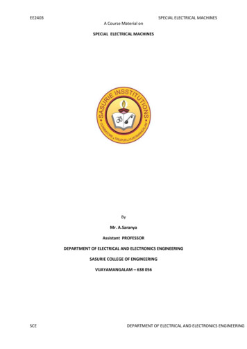
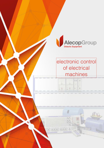
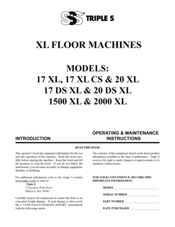
UOT/Elec. Eng. Dep.GE 207/Electrical Machines -I2nd Year/ Comm. Eng. Div.Module IITransformerPage 1 of 16Part A Single-Phase TransformerLecture Note 3Dr. Oday A. AhmedOperating Principles and ConstructionWhat is a Transformer?A transformer is a static piece of equipment used either for raising or loweringthe voltage of an AC supply with a corresponding decrease or increase incurrent.The use of transformers in transmission system is shown in the Figure below.Fig.3-1Principle of OperationA transformer in its simplest form will consist of a rectangular laminatedmagnetic structure on which two coils of different number of turns are wound asshown in Figure 3.2a.Fig.3-2aThe winding to which AC voltage is impressed is called the primary of thetransformer and the winding across which the load is connected is called thesecondary of the transformer.
UOT/Elec. Eng. Dep.GE 207/Electrical Machines -I2nd Year/ Comm. Eng. Div.Module IITransformerPage 2 of 16Part A Single-Phase TransformerLecture Note 3Dr. Oday A. AhmedFig.3-2bDepending upon the number of turns of the primary (N1) and secondary (N2), analternating emf (E2) is induced in the secondary. This induced emf (E2) in thesecondary causes a secondary current I2. Consequently, terminal voltage V2 willappear across the load. If V2 V1, it is called a step up-transformer. On theother hand, if V2 V1, it is called a step-down transformer.When an alternating voltage V1 is applied to the primary, an alternating flux Φis set up in the core. This alternating flux links both the windings and inducesemfs E1 and E2 in them according to Faraday’s laws of electromagneticinduction. The emf E1 is termed as primary emf and emf E2 is termed asSecondary emf.
UOT/Elec. Eng. Dep.GE 207/Electrical Machines -I2nd Year/ Comm. Eng. Div.Module IITransformerPage 3 of 16Part A Single-Phase TransformerLecture Note 3Dr. Oday A. AhmedThe following points may be noted carefully:(i)The transformer action is based on the laws of electromagneticinduction.(ii)There is no electrical connection between the primary and secondary.(iii)There is no change in frequency i.e., output power has the samefrequency as the input power.Can DC Supply be used for Transformers?The DC supply cannot be used for the transformers.Thisisbecausethe transformer works on the principle of mutual induction, for which currentin onefgfcoil must change uniformly.If fDC supply is given, the current will notchange due to constant supply and transformer will not workThere can be saturation of the core due to which transformer draws very largecurrent from the supply when connected to DC.Thus DC supply should not be connected to the transformers.ConstructionWe usually design a power transformer so that it approaches the characteristicsof an ideal transformer. To achieve this, following design features areincorporated:(i)The core is made of silicon steel which has low hysteresis loss andhigh permeability. Further, core is laminated in order to reduce eddycurrent loss. These features considerably reduce the iron losses and theno-load current.(ii) Instead of placing primary on one limb and secondary on the other, itis a usual practice to wind one-half of each winding on one limb. Thisensures tight coupling between the two windings. Consequently,leakage flux is considerably reduced.
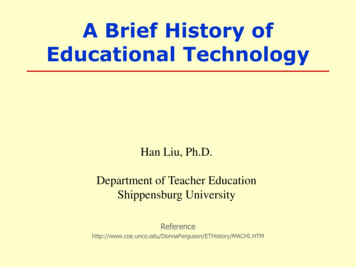
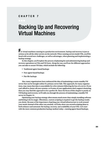
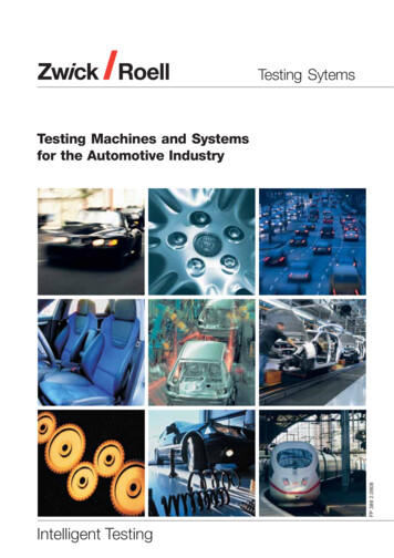
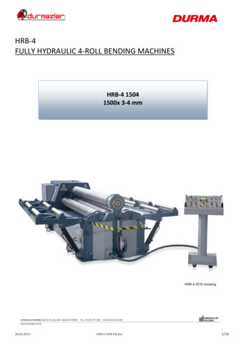
UOT/Elec. Eng. Dep.GE 207/Electrical Machines -I2nd Year/ Comm. Eng. Div.(iii)Module IITransformerPage 4 of 16Part A Single-Phase TransformerLecture Note 3Dr. Oday A. AhmedThe winding resistances are minimized to reduce Copper loss andresulting rise in temperature and to ensure high efficiency.Transformers are of two types: (i) core-type transformer (see Fig.3-3) and(ii) shell-type transformer (see Fig.3-4).Core-Type Transformer: In a core-type transformer, half of the primarywinding and half of the secondary winding are placed round each limb toreduce the leakage flux.Fig.3-3Shell-Type Transformer: This method of construction involves the use of adouble magnetic circuit. Both the windings are placed round the central limbto ensure a low-reluctance flux path.Fig.3-4
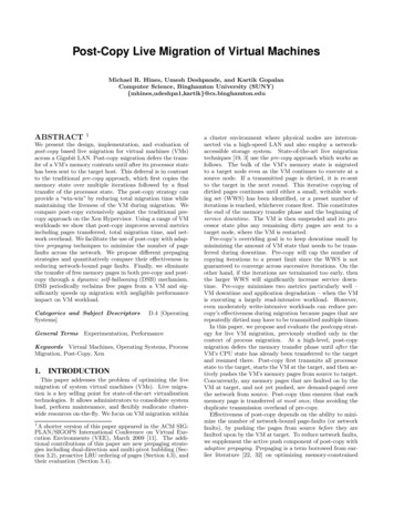
UOT/Elec. Eng. Dep.GE 207/Electrical Machines -I2nd Year/ Comm. Eng. Div.Module IITransformerPage 5 of 16Part A Single-Phase TransformerLecture Note 3Dr. Oday A. AhmedComparison of Core and Shell Type TransformsCore TypeShell TypeThe winding encircles the core.The core encircles most part of the windingIt has single magnetic circuitIt has double magnetic circuitThe core has two limbsThe core has three limbsThe cylindrical coils are used.The multilayer disc or sandwich typecoils are used.The winding are uniformly distributed on twolimbs hence natural cooling is effectivePreferred for low voltage transformers.The natural cooling does not exist as thewindings are surrounded by the core.Preferred for high voltage transformers.Cooling of TransformersWhen transformer supplies a load, two types of losses occur inside thetransformer. The iron losses occur in the core while copper losses occur in thewindings. The power lost due to these losses appears in the form of heat. Thisheat increases the temperature of the transformer. To keep the temperature riseof the transformer within limits, a suitable coolant and cooling method isnecessary.The various cooling methods are designated witch depended upon:A: cooling medium used and B: type of circulation employed.The various coolant used such as Air, Gas, Mineral oil, and water.
UOT/Elec. Eng. Dep.GE 207/Electrical Machines -I2nd Year/ Comm. Eng. Div.Module IITransformerPage 6 of 16Part A Single-Phase TransformerLecture Note 3Dr. Oday A. AhmedOne of cooling method system is shown in figure below which is called OilForced Water Forced cooling system;EMF Equation of a TransformerConsider that an alternating voltage V1 of frequency f is applied to the primaryas shown in Fig. 3-2b. The sinusoidal flux Φ produced by the primary can berepresented as:
UOT/Elec. Eng. Dep.GE 207/Electrical Machines -I2nd Year/ Comm. Eng. Div.Module IITransformerPage 7 of 16Part A Single-Phase TransformerLecture Note 3Dr. Oday A. AhmedVoltage Transformation Ratio (K)From the above equations of induced emf, we have,The constant K is called voltage transformation ratio. Thus if K 5 (i.e.N2/N1 5), then E2 5 E1.Concept of Ideal TransformerA transformer is said to be ideal if it satisfies following properties:i)It has no losses.ii)Its windings have zero resistance.iii) Leakage flux is zero i.e. 100 % flux produced by primary links withthe secondary.iv) Permeabitity of core is so high that negilgiblc current is required toestablish the flux in it.NOTE:For an ideal transformer, the primary applied voltage V1 is same as theprimary induced emf E1 as there are no voltage drops.
UOT/Elec. Eng. Dep.GE 207/Electrical Machines -I2nd Year/ Comm. Eng. Div.Module IITransformerPage 8 of 16Part A Single-Phase TransformerLecture Note 3Dr. Oday A. AhmedFor ideal transformer:Volt-Ampere RatingTransformer rating is specified as the product of voltage and current and calledVA rating.The full load primaty and secondary currents whichjindicate the safe maximumvalues of currents which transformer windings can carry can be given as:Ideal Transformer on No LoadConsider an ideal transformer in Fig. 3-5. For no load I2 0. I1is just necessary to produce flux in the core, which is called magnetising currentImis very small and lagsvV1denotedasIm.0by 90 as the winding is purely inductive.
UOT/Elec. Eng. Dep.GE 207/Electrical Machines -I2nd Year/ Comm. Eng. Div.Module IITransformerPage 9 of 16Part A Single-Phase TransformerLecture Note 3Dr. Oday A. AhmedAccording to Lenz's law, the induced e.m.f.opposes the cause producing itwhich is supply voltage V1. Hence E1 and E2 are in antiphase with V1 but equalin magnitude and E1 and E2 are in phase.Fig.3-5This can be illustrated in the phase diagram as shown below:Ideal Transformer on LoadLet us connect a load ZL across the secondary of an ideal transformer as shownin Figure below:The secondary emf E2 will cause a current I2 to flow through the load:
UOT/Elec. Eng. Dep.GE 207/Electrical Machines -I2nd Year/ Comm. Eng. Div.Module IITransformerPage 10 of 16Part A Single-Phase TransformerLecture Note 3Dr. Oday A. AhmedThe Phasor diagram for the ideal transformer on load is shown in Figure (ii)above.The secondary current I2 lags behind V2 (or E2) by Φ . It causes a primarycurrent I1 KI2 I2 (for K 1) which is in antiphase with it.
UOT/Elec. Eng. Dep.GE 207/Electrical Machines -I2nd Year/ Comm. Eng. Div.Module IITransformerPage 11 of 16Part A Single-Phase TransformerLecture Note 3Dr. Oday A. AhmedPractical TransformerA practical transformer differs from the ideal transformer in many respects. Thepractical transformer has (i) iron losses (ii) winding resistances and (iii)magnetic leakage, giving rise to leakage reactance.(i)Iron losses. Since the iron core is subjected to alternating flux, thereoccurs eddy current and hysteresis loss in it.(ii)Winding resistances. Since the windings consist of copperconductors, it immediately follows that both primary and secondarywill have winding resistance. The primary resistance R1 andsecondary resistance R2 act in series with the respective windings asshown below:(iii)Leakage reactance. Both primary and secondary currents produceflux. The flux Φ which links both the windings is the useful fluxHowever, primary current would produce some flux Φ which wouldnot link the secondary winding and is called mutual flux (for moreinformation review Lecture Note 2) (See Fig. below).
UOT/Elec. Eng. Dep.GE 207/Electrical Machines -I2nd Year/ Comm. Eng. Div.Module IITransformerPage 12 of 16Part A Single-Phase TransformerLecture Note 3Dr. Oday A. AhmedPractical Transformer on No LoadConsider the figure below:The primary will draw a small current I0 to supply (i) the iron losses and (ii) avery small amount of copper loss in the primary. Hence the primary no loadcurrent I0 is not 90 behind the applied voltage V1 but lags it by an angle Φ0 90 as shown in the phasor diagram.The no-load primary current I0 can be resolved into two rectangularcomponents:
UOT/Elec. Eng. Dep.GE 207/Electrical Machines -I2nd Year/ Comm. Eng. Div.Module IITransformerPage 13 of 16Part A Single-Phase TransformerLecture Note 3Dr. Oday A. Ahmedii)Practical Transformer on LoadFig. above shows a practical transformer with the assumption that resistancesand leakage reactances of the windings are negligible. With this assumption, V2 E2 and V1 E1.
UOT/Elec. Eng. Dep.GE 207/Electrical Machines -I2nd Year/ Comm. Eng. Div.Module IITransformerPage 14 of 16Part A Single-Phase TransformerLecture Note 3Dr. Oday A. AhmedLet us take the usual case of inductive load which causes the I2 to lag V2 by Φ2.The total primary current I1 must meet two requirements:Phasor Diagram: Both E1 and E2 lag behind themutual flux f by 90 . The current I'2 representsthe primary current to neutralize thedemagnetizing effect of secondary current I2.Now I'2 K I2 and is antiphase with I2. I0 is theno-load current of the transformer. The phasorsum of I'2 and I0 gives the total primary currentI1. Note that in drawing the phasor diagram, thevalue of K is assumed to be unity so that primaryphasors are equal to secondary phasors.Transformer with resistance and leakage reactanceThe total primary current I1 must meet two requirements:
UOT/Elec. Eng. Dep.GE 207/Electrical Machines -I2nd Year/ Comm. Eng. Div.Module IITransformerPage 15 of 16Part A Single-Phase TransformerLecture Note 3Dr. Oday A. AhmedPhasor Diagram:Note that counter emf that opposes the applied voltageV1 is -E1. Therefore, if we add I1R1 (in phase with I1)and I1 X1 (90 ahead of I1) to -E1, we get the appliedprimary voltage V1. The phasor E2 represents theinduced emf in the secondary by the mutual flux. Thesecondary terminal voltage V2 will be what is left overafter subtracting I2R2 and I2X2 from E2.
UOT/Elec. Eng. Dep.GE 207/Electrical Machines -I2nd Year/ Comm. Eng. Div.Module IITransformerPage 2 of 14Part A Single-Phase TransformerLecture Note 4Dr. Oday A. AhmedModelling and Equivalent Circuits of Single PhaseTransformersThe term equivalent circuit of a transformer means the combination of fixed andvariable resistances and reactances, which exactly simulates performance andworking of the transformer.Impedance RatioConsider a transformer having impedance Z2 in the secondary as shown in thefigure below:
UOT/Elec. Eng. Dep.GE 207/Electrical Machines -I2nd Year/ Comm. Eng. Div.Module IITransformerPage 3 of 14Part A Single-Phase TransformerLecture Note 4Dr. Oday A. AhmedShifting Impedances in a TransformerNOTE:Consider the following figure:We can transfer the parameters from one winding to the other. Thus: A resistance R1 in the primary becomes K2 R1 when transferred to thesecondary. A resistance R2 in the secondary becomes R2/K2 when transferred to theprimary. A reactance X1 in the primary becomes K2 X1 when transferred to thesecondary. A reactance X2 in the secondary becomes X2/K2 when transferred to theprimary.NOTE: When transferring resistance or reactance from primary to secondary,multiply it by K2. When transferring resistance or reactance from secondary to primary,divide it by K2. When transferring voltage or current from one winding to the other, onlyK is used.
UOT/Elec. Eng. Dep.GE 207/Electrical Machines -I2nd Year/ Comm. Eng. Div.Module IITransformerPage 4 of 14Part A Single-Phase TransformerLecture Note 4Dr. Oday A. AhmedA- Referred to primary Equivalent re
There can be saturation of the core due to which transformer draws very large current from the supply when connected to DC. Thus DC supply should not be connected to the transformers. Construction We usually design a power transformer so that it approaches the characteristics of an ideal transformer. To achieve this, following design features are incorporated: (i) The core is made of silicon .