Transcription
HOSPITAL ISOLATION ROOM HVACSYSTEM DESIGNPresented to:ASHRAE YEA Illinois ChapterSpecialty Environment Design ConferenceMarch 24, 2014Jean O. Gibbons, PE, LEED APSenior Vice PresidentGrumman/Butkus AssociatesGrumman/Butkus AssociatesEnergy Efficiency Consultants and Sustainable Design Engineers
Hospital Isolation Room HVAC System Design Types of Isolation Rooms Codes/Standards/References Design Criteria Design Considerations Design Examples
Types of Isolation RoomsAirborne InfectionIsolation (AII) Rooms Used to reduce the spread of airborne infectious diseases (TB)from the patient in the AII Room to the rest of the hospital. Most common type seen in hospitalsProtectiveIsolation/EnvironmentRooms Used to protect the patient (typically an immune suppressedpatient) in the protective environment from commonenvironmental airborne infectious microbes. Less common than AIIConvertible IsolationRooms Rooms that can be converted from an AII Room (negative) to aProtective Environment Room (positive) Out of date concept - not allowed by ASHRAE Standard 170Combination AII/PERooms Used for an immune suppressed patient who has an infectiousdisease. Protects both patient and rest of hospital.
Codes/Standards/References “Guidelines for Environmental Infection Control in Health-Care Facilities”,Recommendations of CDC and the Healthcare Infection Control Practices AdvisoryCommittee (HICPAC), 2003 Codes:o Illinois Administrative Code – will refer to as IDPH Title 77: Public HealthChapter I: Department Of Public HealthSubchapter B: Hospitals And Ambulatory Care FacilitiesPart 250 Hospital Licensing Requirements For HVAC: refer to Section 250.2480 Mechanicalo International Mechanical Code (IMC) - applicable to most suburbso City of Chicago Building Code Standard:o ANSI/ASHRAE/ASHE Standard 170 – Ventilation of Health Care Facilities (2013)o NFPA 101 Guidelineso Facility Guidelines Institute (FGI) Guidelines (2014) – for ventilation refers toASHRAE Standard 170 - 2013
Airborne Infectious Isolation RoomDesign Step 1:Develop HVAC Design CriteriaTemperature, humidity, airflow and pressurization requirementsCDC Temp/humidity – notaddressed Min 12 ach exhaust forrooms constructed since2001 Min 0.01”H2O pressuredifferential to achieveairflow into roomIDPH 75F 30% rh winter min, 60%rh summer max 15 cfm per bed / 10 cfmper bed OA All air exhausted tooutdoors Airflow into roomASHRAEStandard 170-2013(incorporates CDC) 70F-75F – ability tomaintain at all times 60%rh 12 ach minimum totalairflow/2 ach outside air All air exhausted tooutside Negative pressurerelative to adjacent spaces
Airborne Infectious Isolation RoomDesign Step 1:Develop HVAC Design CriteriaUse most stringent of IDPH/ASHRAE Standard 170Temperature:70F to 75FHumidity:30% rh winter min, 60% rh summer maxAirflow:12 ach total/ 2 ach OAPressure:Negative to adjacent areas
Airborne Infectious Isolation RoomArchitectural Design Considerations Ante room withhand wash sink(IDPH Section250-2440)o Note notrequired byFGI or ASHRAE One toilet roomper AII room
Airborne Infectious Isolation RoomArchitectural Design Considerations AII room constructedto minimize leakage areasand allow for room pressurizationo Walls – slab-to-slabo Ceilings – plaster or drywallo Self-closing doors (swing out fornegatively pressurized spaces; swingin for positively pressurized spaces)with door sweepso Sliding doors preferredo Finishes should be smooth andcleanableo Label room use (signage)o Seal all penetrations
Airborne Infectious Isolation RoomPressurization Design ConsiderationsAII room negative toante room/ante roomnegative to corridor(ASHRAE)Min ΔP between AIIroom and adjacentrooms/corridor -0.01”wg (ASHRAE)Min of 10% more EAthan SA but no lessthan 50 cfm New tight construction 200cfm to 300 cfm differential Poorly constructed - 300 cfmto 500 cfmPermanently installedΔP monitoring device(ASHRAE)Provide provisions to change HVAC for normal patient careroom use (IDPH only/different than ASHRAE)
Airborne Infectious Isolation RoomRoom Supply and Exhaust Design Considerations Ante room airflow: 10 ach (ASHRAE) Location of supply diffusers and exhaust grilles - CDC 2003and ASHRAE Standard 170 disagreeo CDC 2003: Supply above patient, exhaust low on wallo ASHRAE Standard 170 2008/2013: “Exhaust grilles or registers shall be located directly above the patient bed on the ceiling or onthe wall near the head of the bed ”o Designer may consider discussing discrepancy with hospitalinfection control.o If chose to supply above patient use non-aspirating laminar flowtype diffusers
Airborne Infectious Isolation RoomOther Design Considerations SA must be from AHU that has code-requiredfiltration:o Min MERV 7 prefilters and MERV 14 final filters(IDPH/ASHRAE) Exhaust air from AII/ante room/toilet room shall notmix with non-AII room exhaust (ASHRAE) Induction units and baseboard heaters should beavoided – surfaces must be cleanable. Use radiantpanels of perimeter heat is required
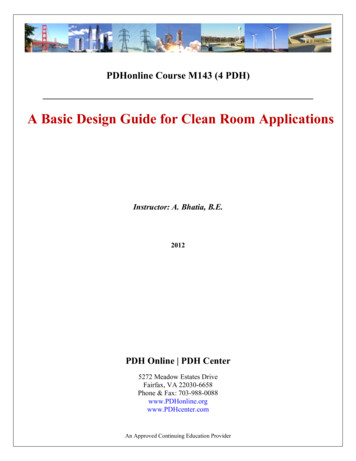
Airborne Infectious Isolation RoomAirflow DiagramDiagram from CDC Guidelines
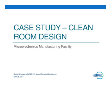
Airborne Infectious Isolation RoomRoom HVAC Design ExampleExhaust system: EA from AHII to maintain 12 ach: 1,500 cfm Toilet exhaust: 100 cfm EA from ante room to maintain 10 ach: 250 cfm Constant volume exhaust box to maintain EA / Total EA 1,400 cfm 100 cfm 250 cfm 1,750 cfmTransfer air from corridor to ante room and ante room to AII room Assume mid range in tightness – use 300 cfm transfer air (TA)Supply system: AII SA EA–TA from ante room TA to toilet /AII SA 1,400 cfm – 300 cfm 100 cfm 1,200 cfm Constant volume box to maintain total SA / Total SA 1,200 cfm 250 cfm 1,450 cfm SA to ante room: 250 cfm (Ante room neutral) Reheat coil to provide space temperature control
Airborne Infectious Isolation RoomRoom HVAC Design Example
Airborne Infectious Isolation RoomRoom HVAC Design Example Example of a AII Ventilation Schedule (numbers donot match example
Airborne Infectious Isolation RoomRoom HVAC Design ExampleExample simplified AII room sequence of operation, including IDPHrequired switch to neutral: Modulate supply CAV air terminal unit damper to maintain supply airflow setpoint. Modulate exhaust air terminal unit damper to maintain exhaust airflow setpoint. Modulate reheat valve and radiation valve to maintain temperature setpoint. Coordinate with users to setup time delay to allow entrance/exit to the pressurizedspace without audible alarm. If an exhaust fan failure alarm is received at the front end, close the supply air terminaldamper operator. When room pressurization state is set to neutral: The BAS shall change CV air terminal unit setpoint such that the AII exhaust airflow isequal to the supply airflow – accounting for TE SA 1,200 cfm EA SA-TA to toilet 1,100 cfm
Airborne Infectious Isolation Room withIDPH Required Neutral State
Airborne Infectious Isolation RoomRoom Pressure Monitors Locate outside of ante room doorin corridor Alarms visually and audibly ifnegative pressure is notmaintained. Tie-in alarm to buildingautomation system To avoid nuisance alarms, controlto a higher point ΔP than to theΔP at which the alarm is seto Control to 0.03” and alarm at 0.01”.
Airborne Infectious Isolation RoomRoom Pressure Monitors Look for monitors that are easy for nursing staff toread and understand.
Airborne Infectious Isolation RoomCentral System Design Exhaust Systemo Locate exhaust fan outside, ifpossibleo If exhaust fan is inside, usewelded duct constructiondownstream of fano Bag in/bag out prefilter/HEPAfilter upstream of the exhaust fano VFDs for the exhaust fan to adjustfan speed as filters load upo Locate fan discharge away from allintakes and above roof, if possibleo Consider large exhaust system toserve multiple rooms instead ofmultiple smaller exhaust systemso Provide emergency power for fans
Airborne Infectious Isolation RoomCentral System Design Supply Systemo Can supply fromsame AHU systemthat serves adjacentpatient roomso Must have MinMERV 7 prefiltersand MERV 14 finalfilters(IDPH/ASHRAE)o Must be able tohumidify to IDPHrequired 30% rh
Protective Isolation RoomDesign Step 1:Develop HVAC Design CriteriaUse most stringent of IDPH/ASHRAE Standard 170Temperature:70F to 75FHumidity:30% rh winter min, 60% rh summer maxAirflow:12 ach total/ 2 ach OAPressure:Positive to adjacent areas
Protective Environment RoomPressurization Design ConsiderationsPE room positive toante room/ante roompositive to corridor(ASHRAE)Min ΔP between PEroom and adjacentrooms/corridor 0.01” wg (ASHRAE)Min of 10% more SAthan EA but no lessthan 50 cfm New tight construction 200cfm to 300 cfm differential Poorly constructed - 300 cfmto 500 cfmPermanently installedΔP monitoring device(ASHRAE)Provide provisions to change HVAC for normal patient careroom use (IDPH only/different than ASHRAE)
Protective Isolation RoomRoom Supply and Exhaust Design Considerations Same requirements as AII room except:o Location of supply diffusers and exhaust grilles ASHRAE Standard 170 “Supply diffusers shall be abovethe patient bed Diffuser design shall limit air velocity atpatient bed to reduce patient discomfort ASHRAE Standard 170 “Return/exhaust grilled shall belocate near the patient door.”o SA must be from AHU that has code-required filtration: Min MERV 7 prefilters and HEPA final filters (ASHRAE) or MERV 14 final filters with terminal HEPA filter
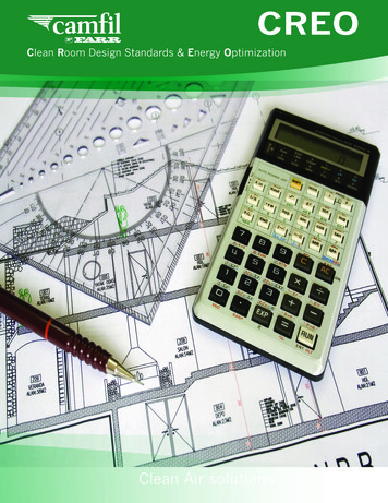
Airborne Infectious Isolation RoomRoom HVAC Design ExampleSupply system: SA from PE to maintain 12 ach: 1,400 cfm SA to ante room: 250 cfm Constant volume box to maintain total SA / Total SA 1,400 cfm 250 cfm 1,650 cfm Reheat coil to provide space temperature controlTransfer air from PE room to ante room and ante room to corridor Assume mid range in tightness – use 300 cfm transfer air (TA)Return/Exhaust system: Air from ante room and PE room may be returned to AHU / RA from Ante Room: 250 cfm Toilet exhaust must be exhausted to outside / TE: 100 cfm PE room RA PE room SA – TA to ante room – TA to toilet 1,400 cfm - 300 cfm - 100 cfm 1,000 cfm Constant volume box to maintain total RA Total RA RA from PE room RA from ante room 1,000 cfm 250 cfm 1,250 cfm
Protective Environment RoomRoom HVAC Design Example
Combination Airborne InfectiousIsolation/Protective Environment Rooms For immune suppressed patients with a airborne infectious disease CDC and ASHRAE 170 allow two options: positive or negative ante room
Combination Airborne InfectiousIsolation/Protective Environment Rooms PE requirements govern supply diffuser and exhaustgrille locations:o ASHRAE Standard 170 “Supply diffusers shall be above thepatient bed.o ASHRAE Standard 170 “Return/exhaust grilled shall belocate near the patient door.” Two permanently installed monitoring devices arerequiredo One between the AII/PE room and the ante roomo One between the ante room and the corridor
Thank YouQuestions?
ASHRAE Standard 170 Return/exhaust grilled shall be locate near the patient door. _ o SA must be from AHU that has code-required filtration: Min MERV 7 prefilters and HEPA final filters (ASHRAE) or MERV 14 final filters with terminal HEPA filter . Airborne Infectious Isolation Room Room HVAC Design Example Supply system: SA from PE to maintain 12 ach: 1,400 cfm SA to ante room: 250 cfm .File Size: 1MBPage Count: 29