Transcription
HVAC DUCT CONSTRUCTIONSTANDARDSMarch, 2010Presented by:Eli HowardExecutive DirectorTechnical ServicesMark TerzigniProject ManagerTechnical Services
HVAC DUCT CONSTRUCTIONSTANDARDS METAL AND FLEXIBLE
Information Required for Duct Construction1. A comprehensive duct layout indicatingsizes, design airflows, pressure class,and routing of the duct system.2. The types of fittings to be used basedon the designer's calculations of fittinglosses (i.e., square versus 45 entrytaps, conical versus straight taps, etc.).
Information Required for Duct Construction3. Use of turning vanes or splitter vanes.4. Location of access doors.5. Location and type of control andbalancing dampers.6. Location and types of diffusers.7. Requirements for duct insulation.
Information Required for Duct Construction8. Location and types of any fireprotection device including firedampers, smoke dampers, combinationfire/smoke dampers, and ceilingdampers. Building codes require thisinformation to be shown on the designdocuments submitted for buildingpermit.
Information Required for Duct Construction9. Details of offsets required to routeductwork around obstructions (columns,beams, etc.).
Information Required for Duct ConstructionENGINEERDesign Considerations:CFMStatic PressureDuct SizeFitting TypeConstructionPressure ClassCONTRACTORConstruction Considerations:Pressure Class(as specified)Panel Thickness (Gage)Panel Width/HeightJoint Type/SpacingIntermediateReinforcementType/Spacing
DEPENDENT VARIABLES
Rectangular Transverse JointsRectangular{ Figure2-1{ Pages2.6-2.9
Rectangular Transverse Joints
Rectangular Transverse Joints
Rectangular Transverse Joints
Rectangular Transverse Joints
Rectangular Transverse Joints
Rectangular Transverse Joints
Rectangular Transverse Joints
Rectangular Transverse Joints
Rectangular Transverse Joints
Figure 2-16Corners not required up to2 in. w.g.Corners are requiredabove 2 in. w.g.
Figure 2-17
Longitudinal Seams{{RectangularFigure 2-17Page 2.10
Longitudinal Seams
Longitudinal Seams
Longitudinal Seams
Intermediate Reinforcement{{RectangularFigure 2-3Page 2.12
Intermediate Reinforcement
Basic Duct Construction Process{{{{{{{Verify pressure classCheck corresponding tableStart with the larger side firstDetermine reinforcement spacing optionsCheck joint reinforcement tablesCheck intermediate reinforcement tablesif applicable (tie rod options)Repeat for the short side
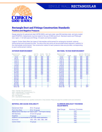
Guide Summary (P 2.5){{{{{Circles are columnnumbersNumber in box is theminimum gageFirst letter is minimumreinforcement classrequired.Second letter isdownsized reinforcementwhen used with tie rodXt – t means tie rod isrequired
In Words {{{{If the box in the table shows H-20GThe minimum panel gage is 20The reinforcement required is class H at thespacing noted at the top of the column (this canbe a joint or intermediate reinforcement)You can use G instead of H if you use a tie rodas well. (If to achieve a class G you are alreadyrequired to use a tie rod then you can not usethis option)
Rectangular Duct Reinforcement
Rectangular Duct Reinforcement
Rectangular Duct Reinforcement
Rectangular Duct Reinforcement
Rectangular Duct Reinforcement
Joint Reinforcement{{{{Table 2-31Starts on page 2.74Covers all transversejoints that qualify asreinforcement exceptT-1 drive slipFor T-1 drive slip seeTable 2-48 on page2.110
Joint Reinforcement
Joint ReinforcementThe (R) means use with a tie rodThe ( ) means use for positivepressure application only
Table 2-48
Example 1{{{{Pressure class is positive 1/2 in. w.g.Dimensions are 20 in. x 12 in.5 ft. joint spacing (longer if possible)Preferred joint type plain Slip and Drive
Example 1Page2.14
Example 1 Table 2-48Not AcceptedPage2.110
Example 1 Solutions{Option 1z Use 24 gagez No reinforcement required either side{Option 2z Use 26 gagez T-1 (plain drive) on the 20 in. side at a maxspacing of 10 ftz No reinforcement required on the 12 in. side
Intermediate Reinforcement{{{{Table 2-29Starts on page 2.70Covers typicalintermediatereinforcement types.For struts see Table2-30 on page 2.72
Intermediate Reinforcement
Intermediate ReinforcementH denotes Hot formedC denotes Cold formed
Example 2{{{{{Pressure Class is 2 in. w.g.Dimensions are 60 in. x 26 in.5 foot joint spacingTDC or TDF jointNo internal reinforcement
The Right Table (Pressure Class)Page2.18
The Right Table (Pressure Class)Page2.18
The Right Table (Pressure Class)Page2.18
Joint ReinforcementPage2.76
Joint ReinforcementPage2.76
Intermediate ReinforcementPage2.70
Intermediate ReinforcementPage2.70
Intermediate Reinforcement
The Right Table (Pressure Class)Page2.18
Joint ReinforcementPage2.76
Example 2 Solution{{{{Duct gage is 20Joint spacing is 5 feet (56 ¼ in.)TDC/TDF for transverse jointIntermediate reinforcement (2 ½ feet)z G class{Angle 1 ½ x 1 ½ x 1/8{Not required on the 26 in. side
Intermediate External Reinforcement{{{{Reinforcement Intervals do not need tocoincideAt 4 in. positive pressure and abovereinforcements must be tiedMust be fastened to the duct within 2 in.from the corner (unless tied)Maximum fastener spacing is 12 in.
Reinforced on Two Sides
Reinforced on Two Sides
Reinforced on Four Sides
Reinforced on Four Sides
Reinforced on Four Sides
Reinforcement Attachment
Tie Rods{Steel Rodz Threaded (all thread) or partialz Plain{Conduitz RCz EMT (most common type){{Steel PipeSteel Strap (positive pressure only)z 1 in. x 1/8 in.{Angles (rare)
Tie Rod Attachment{{Figure 2-5Page 2.82
Tie Rod Attachment{{Figure 2-5Page 2.82
Tie Rod Attachment{{Figure 2-6Page 2.83
Tie Rod Attachment{{Figure 2-6Page 2.83
Tie Rod Layout p 2.98
Mid-Panel Tie Rods{{{Do not use in underground/slab appsDo not use if air velocity 2500 fpmDo not use where grease or condensation cancollectz Unless no penetration is madez Or penetration is sealed water tight{If tie rods occur in 2 directions in the samevicinity they must: (applies to JTR and MPT)z Be prevented from touchingz Or be permanently attached
Example 3{{{{{Pressure class is positive 4 in. w.g.Dimensions are 36 in. x 24 in.5 ft. joint spacingTransverse joint TDC/TDFUse tie rod(s) where possible
The Right Table (Pressure Class)Page2.22
The Right Table (Pressure Class)Page2.22
Joint ReinforcementPage2.76
Joint ReinforcementPage2.76
Joint ReinforcementPage2.76
Mid Panel Tie Rod SchedulePage2.100
Tie Rod LoadPage2.106Table2-46
Mid Panel Tie Rod Size{{{{{EMT conduit positive pressure½ in. 900 lbs¾ in. 1,340 lbs1 in. 1,980 lbsHVAC DCS p2.80 S1.19.4
The Right Table (Pressure Class)Page2.22
Joint ReinforcementPage2.76
Example 3 Solution{{{{Duct gage is 22Joint spacing is 5 feet (56 ¼ in.)TDC/TDF for transverse jointIntermediate reinforcement (2 ½ feet)z 1 MPT{ ½ in. EMT Conduitz Not required on the 24 in. side{Could use 20 gage and JTR also
Mid Panel Tie Rods{{{{Negative pressureuses special tablesConcern is bucklingTable 2-38 in HVACDCS for EMTP 2.91
Mid Panel Tie Rods Neg. PressurePage2.91
Tie Rod Loads{Table 2-46 p. 2.100 is for mid panel tierods (100% load)Table 2-34 p. 2.84 is for tie rods used toback up joints or external reinforcement(75% Load){1 in. w.g. 5.2 lbf/ft2{
Tie Rod Loads{Given information:z 48” wide, RS 28” (TDC/TDF) @ 4 in. w.g.{{{{{Area 48” x 28” 1344 in2Convert to ft2 1344/144 9.33 ft24 in. w.g. x 5.2 lbs/ft2/in. w.g. x 9.33 ft2194 lbfIf backing up a joint or externalreinforcement 194 lbf x .75 146 lbf
An Easier Way?{{Newest addition are the TDC/TDF tablesTables based onz Pressure classz Joint length
Example 3 (revisited){{{{4 in. w.g.TDC/TDF5 ft. joint spacing36 in. x 24 in.
Example 3 (revisited)Table2-19HVACDCSPage{2.50
Example 3 (revisited)Table2-19HVACDCSPage{2.50
Example 3 (revisited)Table2-19HVACDCSPage{2.50
Example 3 (revisited) Solution{Option 1z 20 gagez JTR on 36 in. sidez No additional reinforcement on 24 in. side{Option 2z 22 gagez MPT for 36 in. sidez No additional reinforcement on 24 in. side
Example 3 (revisited) Solution{Option 3z 20 gagez (2) E class reinforcements at the joints for 36 in. sidez No additional reinforcement on 24 in. side{Option 4z 22 gagez F class reinforcement at the mid-panel for 36 in. sidez No additional reinforcement on 24 in. side
Duct over 120 inches{{{Figure 2-13 in HVACDCSUse standard tablesfor sizes 120 in.P 2.117
Duct over 120 inchesPage2.117
Duct over 120 inchesPage2.117
Example 4{Duct is 140 x 70 inches at negative 2 in.w.g.
Duct over 120 inchesPage2.117
Duct over 120 inches{{{{{You need 2 tie rods across the width atevery joint and at every reinforcement.140/60 2.33 (round down) to 2Need 3 at widths beyond 180”140/(2 1) 140/3 46 5/8” spacingThe joint length will be 5 ft. (56 inchesusing TDC/TDF) and the reinforcementspacing will be 2 ½ ft (28 inches usingTDC/TDF).
Duct over 120 inches{{{{Determine the tie rod load:Tip- You can figure the load on a duct ofhalf of the width using Table 2-46 andthen double the load.140/2 70 inchesRS 28 inches
Duct over 120 inchesPage2.106
Duct over 120 inches{{The load is 146 lbs (load for 70 inches) x2 292 lbs for 140 inchesThe load per tie rod is 292 lbs/2 146 lbsz (75% - Rule)What size does the tie rod need to be?{ If we use EMT conduit check Table 2-38What size reinforcement is a class I{ Check Tables 2-29 or 2-30
Mid Panel Tie Rods Neg. PressurePage2.91
Example 4 mid-panel reinforcementPage2.70
Duct over 120 inches{{{Check the short side using the tables forduct less than 120 inches.In this case since we are using TDC/TDFwe can use those specific tables.Table 2-17 on page 2.46
Duct over 120 inchesPage2.46
Example 4 mid-panel reinforcementPage2.70
Example 4 solution{{{{{The duct will be 18 gageThe joints will be TDC/TDFThe joint length is 56 inchesThe 140 inch side will be supported by 1” EMTconduit spaced 46 5/8” across the width and willbe at each side of the joint and backing up themid-panel reinforcement.The mid-panel reinforcement for the 140 inchside will be 2 ½ x 2 ½ x 1/8 and will be tiedusing 1 x 1 x 12 gage
Example 4 solution{{{{The 70 inch side will be reinforced usingonly external reinforcementThe reinforcement will be 2 x 2 x 1/8 andinstalled on both sides of each jointThis reinforcement will not be tiedNo mid-panel reinforcement is required
Example 4 solutionPage2.117
Example 5 Round Duct{{{{Positive 10 in. w.g.24 in. diameterLong seam or spiralTable 3-5 in HVAC DCSz Applies to positive pressure up through 10 in.w.g.
Table 3-5 Page 3.8Unreinforced Round Duct to Positive 10 in. w.g.Example 3 Round Duct
Table 3-5 Page 3.8Unreinforced Round Duct to Positive 10 in. w.g.Example 3 Round Duct
Example 6 Round Duct{{{{{Negative 10 in. w.g.24 in. diameterLong seam SpiralTable 3-9 in HVAC DCS for long seamTable 3-13 in HVAC DCS for spiral
Example 4 long seamLongitudinal SeamPage 3.16
Example 4 SpiralSpiral SeamP 3.24
Round Reinforcement{Tables in the HVACDCSz 3-2 Reinforcementz 3-3 AttachmentSchedulez 3-4 Rings Used asCompanion Flangesz P 3.6
Round ReinforcementPage 3.6
Round ReinforcementPage 3.6
Oval Duct{Approved for positive pressure onlyz Can be used for negative pressure withspecial designs{{Table 3-15 for gageReinforce like rectangularz Based on the flat span{Flat span major – minorz Based on reinforcement spacingz Use at least one tie rod (Figure 3-7 p 3.32)
Oval DuctPage 3.28
Example 7 Oval Duct{Flat Oval Duct 20” x 46” @ 10 in. w.g.z Major dimension 46”z Minor dimension 20”z Flat span (Major – Minor) 26” (46” - 20”){First step determine gagez Use Table 3-15z Use Major dimension
Example 7 Oval DuctPage 3.28
Example 7 Oval Duct{Next determine the reinforcementz Based on the flat span (26”)z Use the correct rectangular tablez Pick reinforcement spacingz Determine reinforcement class
Example 7 Oval DuctPage 2.26
Example 7 Oval Duct Solution{Using spiral ductz Build the duct from 22 gage materialz Reinforce the duct every 5 feetz Use a G class reinforcement{1 ½ x 1 ½ x 1/8 anglez Use either type 1 or type 2 option for tie rod{Figure 3-7 page 3.32
Questions?Technical Inquiries:www.smacna.orgzClick on technical services (left side)zClick on technical inquiries fuseaction inquiry
The duct will be 18 gage {The joints will be TDC/TDF {The joint length is 56 inches {The 140 inch side will be supported by 1” EMT conduit spaced 46 5/8” across the width and will be at each side of the joint and backing up the mid-panel reinforcement. {The mid-panel reinforcement for the 140 inch side will be 2 ½ x 2 ½ x 1/8 and will be tied