Transcription
AirWave VisualRF Location and MappingAruba White PaperAirWave VisualRF Location and Mapping:Improving Operations EfficiencyThroughout the Wireless Network Lifecycle
AirWave VisualRF Location and MappingAruba White PaperTable of ContentsIntroduction3VisualRF Overview: Making the Airwaves Visible3How VisualRF Works4Setup and Tuning4Pre-Deployment Planning and Provisioning5Network Monitoring and Troubleshooting6Managing Security and Compliance8Architectural Overview9A New Focus on Wired Management10Summary11About Aruba Networks, Inc.12Aruba Networks, Inc.2
AirWave VisualRF Location and MappingAruba White PaperIntroductionDriven by the need for mobility, higher productivity and cost reductions through network rightsizing, wirelessnetworks are becoming ubiquitous within all enterprises, government organizations and educational institutions.As wireless evolves into the primary means of connectivity for some of the organization’s most important users,network managers need to be more efficient in how they plan, manage and protect their growing wirelessLANs (WLANs).IT organizations are quickly discovering that WLANs bring a unique set of characteristics, including: Users that connect from different locations at different times, and sometimes with different devices Dependence on a medium that is out of IT’s control — the airTo really understand what is happening on your wireless network, IT needs the ability to monitor the whole RFenvironment — down to the device and user level. Unfortunately, very few solutions provide this level of visibility.The best solutions take into account the full complexity of the RF environment and address the followingrequirements: Predictive and dynamic sampling. Purely predictive or site survey tools only offer a simple snapshot or statisticalsampling of the environment. Solutions need to combine both predictive models and sampling of real-world datato effectively support the full network lifecycle from planning to troubleshooting. Multi-vendor support. Products that only manage a single vendor’s infrastructure — or even a singlegeneration of that vendor’s products — provide a similarly incomplete picture. Support for multi-vendor andmulti-architecture environments is critical to provide a complete picture of the RF environments that exist inmost enterprises. Full-time location engine. Products that only capture location data during troubleshooting events typically arenot as fast or accurate as an engine that continuously tracks the location of every device. Leveraging existing infrastructure. Tools that focus only on location services typically require expensivededicated infrastructure components, such as sensors and exciters, plus separate application servers. Theseadded costs put the solutions out of reach for many organizations. Tracking across the edge of the network. Most APs use power over Ethernet to acquire power and data throughone cable. However, beyond 300 feet of wired cable, wired signals passed to the AP can be significantlydegraded. Effective solutions can visually model capacity and power constraints, which is a valuable capabilityin capacity planning.AirWave VisualRF Location and Mapping provides an end-to-end wireless network visualization and lifecyclemanagement solution from initial site planning to ongoing RF monitoring. As a feature of the AirWave WirelessManagement Suite from Aruba Networks, VisualRF uses dynamic signal propagation technology to accuratelycalculate signal coverage and the precise location of every wireless device in range of the WLAN. VisualRF exposesthis information via an interactive web interface, displaying fully integrated maps and location information. WithVisualRF, organizations can solve network problems faster, reduce costs, improve service quality for users andmake better-informed network planning and deployment decisions.VisualRF Overview: Making the Airwaves VisibleVisualRF automatically generates a real-time picture of the RF environment so that IT staff can visualize theentire network from the core infrastructure and throughout the entire RF environment without having to leavetheir desks.Aruba Networks, Inc.3
AirWave VisualRF Location and MappingAruba White PaperVisualRF offers significant advantages: Saves time. VisualRF creates a live map of the entire wireless network infrastructure and automatically tracks anydevice that associates with the network, including laptops, printers, smartphones and even many Wi-Fi assettags — without any additional setup. Up-to-date RF heat and channel maps as well as highly accurate locationdata help the service desk and Level 2/3 support staff to pinpoint and resolve coverage problems faster with lessdirect involvement from users. Saves money. As an integrated feature of AirWave, VisualRF is very cost-effective to deploy. It leverages existingreal-time information from the network infrastructure. There is no need to install separate dedicated sensors,exciters or location appliances, nor does the product require expensive site surveys or the input of walls and wallproperties. The product’s bulk floor plan import capability saves hundreds or thousands of man-hours duringsetup for organizations with large networks comprising thousands of locations. Consequently, organizations cangain higher value without adding anything to their existing infrastructure. Robust visibility. VisualRF couples predictive modeling with calculated modeling based on real RF samples toproduce the most accurate representation of the RF environment. As a result, VisualRF provides a completepicture of your network, even in multi-vendor, mixed-architecture environments that combine thick and thinaccess points (APs), mesh APs, point-to-point APs, 802.11 and WiMAX. Improves service quality. Good network planning is crucial, since infrastructure deployment mistakes may becostly and time-consuming to fix. VisualRF helps you do it right the first time, heading off potential service callsfrom frustrated users. If you do have a coverage gap, VisualRF makes it clear where the problem exists so youcan take immediate, appropriate action. Enables smarter planning. VisualRF enables companies to intelligently plan campuses, buildings, floors and APs.Complete bills-of-materials allow planners and installation contractors to streamline the quote and installationprocess for both the wired and wireless infrastructure. Improves security. VisualRF helps you quickly locate rogue devices within your WLAN, as well as devices thatare out of security compliance.How VisualRF WorksVisualRF provides a comprehensive view of the entire building and campus network infrastructure, enabling ITto see exactly who is on the network, where they are located and how the overall network is performing.VisualRF requires few resources to set up, deploys cost-effectively and provides significant advantagesthroughout the entire wireless network lifecycle from pre-deployment provisioning and planning to ongoingmonitoring and troubleshooting to rogue AP detection and threat mitigation.Setup and TuningInstalled on the same server as the AirWave Management Platform (AMP) software, VisualRF setup is fastand straightforward. Once activated, the feature leverages RF data from your existing infrastructure, includingall your routers and access points that are managed by AMP. All location engines require uploading floor plansand locating access points. VisualRF has refined the process to make it as easy as possible. You can uploadfiles directly into the server or utilize VisualRF Plan, a desktop version of VisualRF’s planning capabilities thatdoes not require access to the server.VisualRF supports all versions of CAD, including DWG, DWF and DFX formats. It also supports JPEG, GIF,BMP and PNG file formats. VisualRF automatically inherits size information stored in CAD files while providingcropping, de-layering and de-coloring capabilities. For organizations with multiple campuses, buildings, andfloor plans, a batch upload feature is available to import thousands of files programmatically, saving hundredsof staff hours. In one case, a retailer estimated that it would take a full staff-year to upload its 2,000 floor plans.It was pleasantly surprised when one employee used VisualRF’s batch upload capabilities to complete the taskin just one week!Aruba Networks, Inc.4
AirWave VisualRF Location and MappingAruba White PaperVisualRF automatically incorporates live RF data from all managed access points and inherits device-typegrouping information from AMP. For companies with multi-vendor and mixed-architecture environments,VisualRF automatically normalizes RF data from multiple vendors’ APs and across different product lines fromthe same vendor. Different types of associated client devices are displayed using different icons, allowing usersto easily view and monitor the status of a wide range of devices, including laptops, PDAs, Wi-Fi asset tags andwireless VoIP phones. You can plan switches and routers and depict them within an wiring closet (or IDF).Understanding the wired topology enables VisualRF to help with the root cause of wireless issues that areactually related to the wired network.VisualRF generally achieves resolution below 10 meters in properly deployed WLAN installations without requiringspecial sensors or site surveys. It offers a number of features that help refine location accuracy, including: A location accuracy testing tool, which records location accuracy and allows you to compare before-and-afterresults before making changes to the RF environment. A remote site survey tool that allows you to perform cost-effective surveys using any client connected to theinfrastructure without the burden of carrying a specialized device to the physical location. For example, you caninstruct VisualRF to take signal samples from a specific client device at a known location coordinate to estimatethe path loss at that particular area of a floor. This increases the location and path loss accuracy for all clients inthat specified area.Pre-Deployment Planning and ProvisioningIntelligent planning can save substantial time and costs by avoiding the need to reinstall or reconfigure awireless network that does not meet coverage requirements. Using VisualRF, wireless network engineers canquickly model floor plans for wireless and wired infrastructures, specifying precise controller and access pointlocations, as well as determining the required wired upstream infrastructure. As a result, VisualRF helpsorganizations optimize network performance before any infrastructure is put in place.VisualRF includes VisualRF, a web-based network planning application that can run on the AMP server, andVisualRF Plan, which operates locally on your desktop. Both VisualRF and VisualRF Plan leverage the samecode base and deliver the same planning feature set within a consistent user interface. You can automate theimport and export of site plans between VisualRF and VisualRF Plan. AirWave provides VisualRF Plan free ofcharge for any customers with a valid Aruba support agreement. Networks planned within VisualRF Plan can beexported to Microsoft Word format, making it easy to share information with your extended team.The VisualRF planning process consists of the following steps:1. Upload your floor plans. Whether you are installing a wireless network for the first time or expanding anexisting one, VisualRF Plan can facilitate the planning process. Before you have your AMP server inplace, you can import your campuses, buildings and floor plans to the VisualRF system from VisualRFPlan, Cisco WCS, and Aruba OS or RF Plan. You can manually upload floor plans based on a wide rangeof formats, including CAD, JPEG and GIF.2. Placing wireless networking equipment on a floor plan. VisualRF optimizes AP placement by analyzingyour floor plan and determining the number and exact location of APs based on the following variables:coverage criteria, building characteristics, manufacturer and model. For example, you could establish thatall areas in your building must have a certain level of coverage. The product includes a wireless catalogthat contains all of the RF characteristics for any device supported in AirWave, including minimum receivesensitivities per radio, antenna gain and antenna coverage properties, so that your design takes intoaccount the unique characteristics of your chosen infrastructure. If you are planning to use Aruba airmonitors as an overlay system for your wireless intrusion protection system (WIPS), VisualRF canoptimize placement of these sensors.Aruba Networks, Inc.5
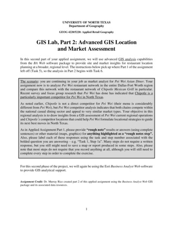
AirWave VisualRF Location and MappingAruba White Paper3. Placing wired network equipment on a floor plan. To assist in the planning process, VisualRF provides thecapability to plan for wired network equipment necessary to support the WLAN equipment. It provides aview that displays the distance between the AP and the IDF. This allows you to determine the necessaryrequired cabling and power requirements of the planned AP, as well as verifies that the planned wireddevices will meet your requirements.Figure 1. VisualRF auto-provisions APs on a floor plan.4. Validation and purchasing. VisualRF automatically generates bill-of-material reports. The BOMs provide ahard-copy validation of the technical requirements (in terms of desired RF characteristics) and a completelist of equipment (wired and wireless) required to install the network. This information makes purchasingand contracting for physical installation much easier because you have a table of part numbers andquantities with a graphical representation of the network. The report can be delivered in HTML orMicrosoft Word 2007 format.Network Monitoring and TroubleshootingVisualRF enables organizations to reduce the support and operational costs associated with managing awireless network. In addition to providing a real-time view of the RF environment, the product automaticallytracks the location of all devices that associate with the network, including laptops, printers, smartphone andWi-Fi asset tags.Aruba Networks, Inc.6
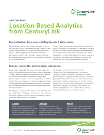
AirWave VisualRF Location and MappingAruba White PaperA number of capabilities are available to IT staff — both service desk and Level 2/3 support staff — to assist introubleshooting. First and foremost, VisualRF provides real-time visual overlays, including: Heat maps — depict the strength of the RF coverage in each location. VisualRF uses a unique dynamic RFsampling technique that incorporates AP-to-AP, AP-to-client and AP-to-rogue data to build an attenuation gridthat graphically indicates coverage levels. If you have dedicated sensors in place, the data from those sensors(sensor-to-AP, sensor-to-client and sensor-to-rogue) will also feed into the dynamic RF sampling. VisualRFautomatically recalculates the path loss and device locations as it receives real-time data from the wireless LAN. Data rate — calculates the data rate at every location using dynamic RF sampling. Color-coded channels — help reduce interference and recommend RF channel and other settings for optimalperformance and coverage. Voice overlay — indicates how well the network is functioning relative to voice coverage. Google Earth integration — shows device locations and mesh network links for outdoor deployments. Sensor coverage — this features displays the areas that are covered by your air monitors and those that are not,so that you can verify that you are providing adequate coverage for rogue scanning.Figure 2. VisualRF’s heat map view depicts the strength of the RF coverage in each location.Aruba Networks, Inc.7
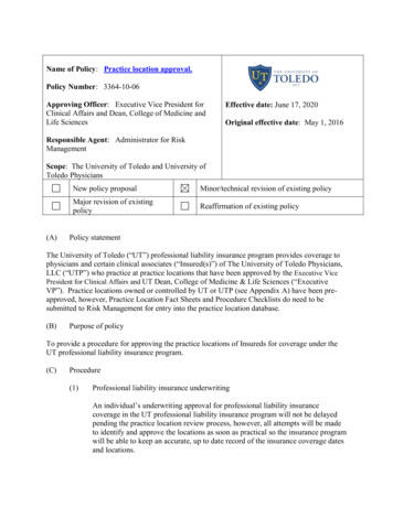
AirWave VisualRF Location and MappingAruba White PaperVisualRF includes location playback capabilities, allowing you to play back up to 24 hours of location history onyour screen. This capability assists with troubleshooting — for example, if a user is not sure exactly where he orshe was when a problem occurred — and with finding lost or stolen devices. VisualRF also displays the ‘‘lastknown location’’ if a device disappears off the network.Asset Tracking: Real World ScenarioA university library that offered rental computers had lost one of its computer units. Weeks after it was reported missing, theIT department located the unit using VisualRF. The IT team used AirWave Wireless Management Suite to set an alert to betriggered when the device was associated to the wireless network. When the machine was eventually turned on, the alertwas received, and the IT team was able to use VisualRF to track it down to a cart in a storage closet.With VisualRF, users customize their view to suit specific preferences and requirements. For example, thefeature offers: Visual alerts and personal thresholds — user-defined alerts and error conditions can be displayed on the floorplan, clearly indicating the alert location and making error patterns easier to resolve. Alerts can be based on predefined thresholds or YES/NO and are color-coded for higher visibility. For example, you can establish specificbreakpoints for when a user consuming large amounts of bandwidth shows up as green, yellow or red. Grid lines — VisualRF layers grid lines on the coverage map, facilitating a more intuitive view for troubleshootingin some physical environments. Custom device types — users can customize device type icons including the icon size, for example to distinguisha laptop from a printer. If you have a previously deployed network that is experiencing coverage problems, youcan use VisualRF to determine if coverage will improve if you add more APs. You can review before-and-after RFmaps to compare the current setup to the proposed optimal configuration. In addition, you can address potentialcoverage problems proactively with a ‘‘simulate failure’’ feature that allows you to examine what happens if anexisting AP fails. This allows you to incorporate the right level of redundancy into mission-critical networks.Managing Security and ComplianceVisualRF integrates with AirWave RAPIDS , the rogue detection feature of AirWave Wireless ManagementSuite, and provides rogue AP locations on your floor plans for faster mitigation and removal. The featureprovides clues as to which wired subnet any rogue devices are located in. VisualRF can also validate coveragefor dedicated sensors such as Aruba air monitors for better location accuracy and PCI compliance.Figure 3. VisualRF displays the locations of all rogue devices found by RAPIDS.Aruba Networks, Inc.8
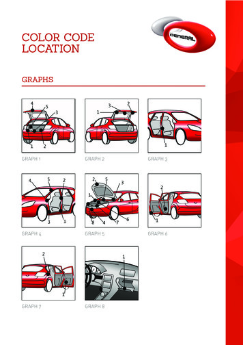
AirWave VisualRF Location and MappingAruba White PaperArchitectural OverviewVisualRF is an integrated feature of AirWave. At the core is the AirWave Management Platform (AMP), whichprovides efficient centralized management of the wireless infrastructure. AMP communicates with APs,controllers, switches and routers over SNMP at configurable intervals.These components return a vast amount of RF signal information, such as AP-to-AP, AP-to-client, and AP-torogue, which when received by AMP, is routed to VisualRF. As a full-time location engine, VisualRF continuallycalculates RF coverage and device locations for all wireless clients within your WLAN airspace. In addition,through integration with the RAPIDS feature, VisualRF calculates the location of rogue devices and all devicesthat are associated with the wireless network. VisualRF then presents this data to the user via a Flash interface.FlashInterfaceXML API forLocation ServicesVisualRF Services (location & path loss)AirWave Management PlatformSNMPpolling800Wired edgeswitchesControllersAPsFigure 4. The AirWave Management Platform, a core component of the AirWave Management Suite, provides efficient,centralized management of your wireless infrastructure and visibility across the wired edge of your network.VisualRF is unparalleled in the way it calculates path loss and device locations. AirWave uses a combination ofboth dynamic RF sampling to determine signal path loss at a particular site and a p
tags — without any additional setup. Up-to-date RF heat and channel maps as well as highly accurate location data help the service desk and Level 2/3 support staff to pinpoint and resolve coverage problems faster with less direct involvement from users. Saves money. As an integrated f