Transcription
Multicast configuration on Brocade FastIron SwitchesThis guide is to assist in the basic understanding and configuration of IGMP snooping and PIMon Brocade ICX, FCX, and SX devices. More detailed information can be found in the “Brocade IPMulticast Configuration Guide”.IGMP snooping overviewWhen a device processes a multicast packet, by default, it broadcasts the packets to all portsexcept the incoming port of a VLAN. Packets are flooded by hardware without going to the CPU.This behavior causes some clients to receive unwanted traffic.IGMP snooping provides multicast containment by forwarding traffic to only the ports that haveIGMP receivers for a specific multicast group (destination address). A device maintains theIGMP group membership information by processing the IGMP reports and leave messages, sotraffic can be forwarded to ports receiving IGMP reports.An IPv4 multicast address is a destination address in the range of 224.0.0.0 to 239.255.255.255.Addresses of 224.0.0.X are reserved. Because packets destined for these addresses may requireVLAN flooding, devices do not snoop in the reserved range. Data packets destined to addressesin the reserved range are flooded to the entire VLAN by hardware, and mirrored to the CPU.Multicast data packets destined for the non-reserved range of addresses are snooped. A clientmust send IGMP reports in order to receive traffic.IGMP protocols provide a method for clients and a device to exchange messages, and let thedevice build a database indicating which port wants what traffic. The protocols do not specifyforwarding methods. They require IGMP snooping or multicast protocols such as PIM to handlepacket forwarding. PIM can route multicast packets within and outside a VLAN, while IGMPsnooping can switch packets only within a VLAN.If a VLAN is not IGMP snooping-enabled, it floods multicast data and control packets to theentire VLAN in hardware. When snooping is enabled, IGMP packets are trapped to the CPU.Data packets are mirrored to the CPU in addition to being VLAN flooded. The CPU then installshardware resources, so that subsequent data packets can be switched to desired ports inhardware without going to the CPU. If there is no client report or port to queriers for a datastream, the hardware resource drops it.
Configuring the IGMP modeYou can configure active or passive IGMP modes on the Brocade device. The default mode ispassive. If you specify an IGMP mode for a VLAN, it overrides the global setting. Active - When active IGMP mode is enabled, a Brocade device actively sends out IGMPqueries to identify multicast groups on the network, and makes entries in the IGMPtable based on the group membership reports it receives.NOTE: Routers in the network generally handle this operation. Use the active IGMPmode only when the device is in a stand-alone Layer 2 Switched network with noexternal IP multicast router attachments. In this case, enable the active IGMP mode ononly one of the devices and leave the other devices configured for passive IGMP mode. Passive - When passive IGMP mode is enabled, it forwards reports to the router portswhich receive queries. IGMP snooping in the passive mode does not send queries.However, it forwards queries to the entire VLAN.Configuring the global IGMP modeTo globally set the IGMP mode, enter the following command.device(config)#ip multicast passiveSyntax: [no] ip multicast [active passive]If you do not enter either active or passive, the passive mode is assumed.Configuring the IGMP mode for a VLANIf you specify an IGMP mode for a VLAN, it overrides the global setting.To set the IGMP mode for VLAN 20, enter the following commands.device(config)#vlan 20device(config-vlan-20)#multicast passiveSyntax: [no] multicast [active passive]
Configuring the IGMP versionUse the procedures in this section to specify the IGMP version.Configuring the global IGMP versionWhen you globally enable IGMP snooping, you can specify IGMP V2 or IGMP V3. The ipmulticast version command enables IGMP V3.device(config)#ip multicast version 3Syntax: [no] ip multicast version [2 3]If you do not specify a version number, IGMP V2 is assumed.Configuring the IGMP version for a VLANYou can specify the IGMP version for a VLAN. For example, the following commands configureVLAN 20 to use IGMP V3.device(config)#vlan 20device(config-vlan-20)#multicast version 3Syntax: [no] multicast version [2 3]If no IGMP version is specified, then the globally-configured IGMP version is used. If an IGMPversion is specified for individual ports, those ports use that version, instead of the VLANversion.Overview of IP multicastingMulticast protocols allow a group or channel to be accessed over different networks by multiplestations (clients) for the receipt and transmission of multicast data.PIM is a broadcast and pruning multicast protocol that delivers IP multicast datagrams. Thisprotocol employs reverse path lookup check and pruning to allow source-specific multicastdelivery trees to reach all group members. PIM builds a different multicast tree for each sourceand destination host group.Concurrent support for multicast routing and snoopingMulticast routing and multicast snooping instances work concurrently on the same device. Forexample, you can configure PIM routing on certain VEs interfaces and snooping on other VEs orVLANs. The limitation is that either multicast snooping or routing can be enabled on a VEinterface or VLAN, but not on both. This is because all of the multicast data and control packets
(IGMP, PIM) received on the snooping VLAN are handled by multicast snooping and do notreach the multicast routing component. Similarly, any multicast data or control packetsreceived on a VE interface enabled with PIM routing are handled by the PIM routing componentand are not seen by the IGMP or PIM snooping component.The following considerations apply when configuring concurrent operation of Multicast Routingand Snooping.1. Either multicast snooping or routing can be enabled on a VE or VLAN but not both.2. Snooping can be enabled globally by configuring the ip multicast active passivecommand.3. The global snooping configuration is inherited by all current VLANs that are not enabledfor multicast routing.4. The global snooping configuration is also inherited by all new VLANs. Enabling multicastrouting on a newly created VLAN or VE automatically disables snooping on the VLAN orVE.5. When a VLAN-level snooping is configured, it is displayed.PIMThere are two modes in which PIM operates: Dense and Sparse. The Dense Mode is suitable fordensely populated multicast groups, primarily in the LAN environment. The Sparse Mode issuitable for sparsely populated multicast groups with the focus on WAN.PIM uses the IP routing table instead of maintaining its own, thereby being routing protocolindependent.Globally enabling and disabling PIMTo globally enable PIM, enter the following command.device(config)# router pimSyntax:[no] router pimThe [no] router pim command behaves in the following manner: Entering a router pim command to enable PIM does not require a software reload.Entering a no router pim command removes all configuration for PIM multicast on adevice (router pim level) only.
Configuring PIM interface parametersAfter you enable IP multicast routing and PIM Sparse at the global level, you must enable it onthe individual interfaces connected to the PIM Sparse network.To enable PIM Sparse mode on an interface, enter commands such as the following.device(config)# interface ethernet 1/2/2device(config-if-e10000-1/2/2)# ip address 207.95.7.1 255.255.255.0device(config-if-e10000-1/2/2)# ip pim-sparseSyntax: [no] ip [pim-sparse pim-dense]The commands in this example add an IP interface to port 1/2/2, then enable PIM Sparse on theinterface.If the interface is on the border of the PIM Sparse domain, you also must enter the followingcommand.device(config-if-e10000-1/2/2)# ip pim borderSyntax: [no] ip pim borderConfiguring BSRsIn addition to the global and interface parameters described in the previous sections, you needto identify an interface on at least one device as a candidate PIM Sparse Bootstrap router (BSR)and candidate PIM Sparse rendezvous point (RP).NOTE: It is possible to configure the device as only a candidate BSR or RP, but it is recommendedthat you configure the same interface on the same device as both a BSR and an RP.To configure the device as a candidate BSR, enter commands such as the following.device(config)# router pimdevice(config-pim-router)# bsr-candidate ethernet 1/2/2 30 255These commands configure the PIM Sparse interface on port 1/2/2 as a BSR candidate, with ahash mask length of 30 and a priority of 255.Syntax: [no] bsr-candidate { ethernet unit/slot/port loopback num ve num tunnel } numhashmask-length [ priority ]The ethernet unit/slot/port, loopback num, ve num, and tunnel num parameters specify theinterface.The device will advertise the IP address of the specified interface as a candidate BSR.
Enter ethernet unit/slot/port for a physical interface (port).Enter ve num for a virtual interface.Enter loopback num for a loopback interface.Enter tunnel num for a GRE tunnel interface.The numhash-mask-length variable specifies the number of bits in a group address that aresignificant when calculating the group-to-RP mapping. You can specify a value from 1 to 32.NOTE: it is recommended that you specify 30 for IP version 4 (IPv4) networks.The priority variable specifies the BSR priority. You can specify a value from 0 to 255. When theelection process for BSR takes place, the candidate BSR with the highest priority becomes theBSR. The default is 0.Configuring RPsEnter a command such as the following to configure the device as a candidate RP.device(config-pim-router)# rp-candidate ethernet 1/2/2Syntax: [no] rp-candidate ethernet { ethernet unit/slot/port loopback num ve num tunnelnum }The ethernet unit/slot/port, loopback num, ve num, and tunnel num parameters specify theinterface.The device will advertise the IP address of the specified interface as a candidate RP. Enter ethernet unit/slot/port for a physical interface (port).Enter ve num for a virtual interface.Enter loopback num for a loopback interface.Enter tunnel num for a GRE tunnel interface.By default, this command configures the device as a candidate RP for all group numbersbeginning with 224. As a result, the device is a candidate RP for all valid PIM Sparse groupnumbers. You can change this by adding or deleting specific address ranges.The following example narrows the group number range for which the device is a candidate RPby explicitly adding a range.Device(config-pim-router)# rp-candidate add 224.126.0.0 16Syntax: [no] rp-candidate add group-addr mask-bits
The group-addr mask-bits variable specifies the group address and the number of significantbits in the subnet mask. In this example, the device is a candidate RP for all groups that beginwith 224.126.When you add a range, you override the default. The device then becomes a candidate RP onlyfor the group address ranges you add.You also can delete the configured rp-candidate group ranges by entering the followingcommand.device(config-pim-router)# rp-candidate delete 224.126.22.0 24Syntax: [no] rp-candidate delete group-addr mask-bitsThe usage of the group-addr mask-bits parameter is the same as for the rp-candidate addcommand.
Show CommandsDisplaying the IGMP snooping configurationTo display the global IGMP snooping configuration, enter the show ip multicast command atany level of the CLI.Displaying IGMP group informationTo display default, maximum, current, and configured values for system maximum parameters,use the show default values command. The following output example does not show completeoutput; it shows only IGMP group values.To display information about IGMP groups, enter the show ip multicast group command.
Displaying IGMP snooping mcache informationThe IGMP snooping mcache contains multicast forwarding information for VLANs. To displayinformation in the multicast forwarding mcache, enter the show ip multicast mcache command.Displaying the status of IGMP snooping trafficTo display status information for IGMP snooping traffic, enter the show ip multicast trafficcommand.Displaying basic PIM Sparse configuration informationTo display PIM Sparse configuration information, enter the following command at any CLI level.
Displaying a list of multicast groupsTo display PIM group information, enter the following command at any CLI level.Displaying PIM mcache table entriesTo display PIM mcache information, enter the following command at any CLI level.
Displaying BSR informationTo display BSR information, enter the following command at any CLI level.Displaying candidate RP informationTo display candidate RP information, enter the following command at any CLI level.
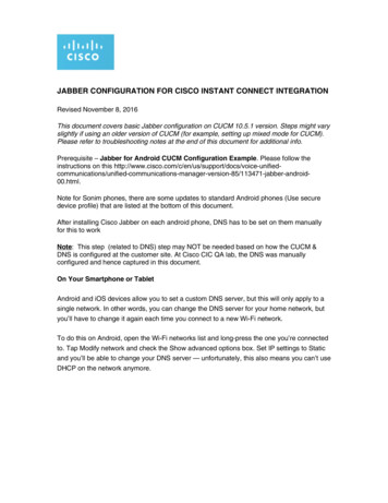
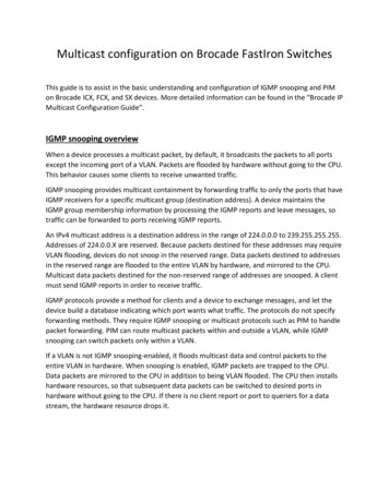
Example:The following example shows how to configure IGMP snooping and PIM-Sparse on twonetworks that need to transport multicast information from a source to a client. For thisexample, we are using Brocade ICX routers and switches as the infrastructure. We are using VLCas the source on a server and VLC player on two windows clients on different networks.Figure 1:Router-RP10.100.0.1Router A10.100.0.2Switch ASwitch BClient 1VLAN 3010.10.30.100Client 2VLAN 1010.20.10.100Router-RP Configurationver 08.0.30dT7f3!stack unit 1module 1 icx6610-48-port-management-modulemodule 2 icx6610-qsfp-10-port-160g-modulemodule 3 icx6610-8-port-10g-dual-mode-modulestack-trunk 1/2/1 to 1/2/2
stack-trunk 1/2/6 to 1/2/7stack mac 748e.f8e6.cc80!global-stp!vlan 1 name VLAN1 by porttagged ethe 1/1/43 to 1/1/47spanning-tree 802-1wspanning-tree 802-1w priority 8192!vlan 10 name Network by porttagged ethe 1/1/1 ethe 1/1/3 to 1/1/10 ethe 1/1/35 to 1/1/36 ethe 1/1/43 to 1/1/47 ethe/3/1 ethe 1/3/3untagged ethe 1/1/12 to 1/1/20router-interface ve 10spanning-tree 802-1wspanning-tree 802-1w priority 8192!vlan 20 name Voice by porttagged ethe 1/1/1 to 1/1/10 ethe 1/1/35 to 1/1/36 ethe 1/1/43 to 1/1/47 ethe 1/3/1 ethe/3/3router-interface ve 20spanning-tree 802-1wspanning-tree 802-1w priority 8192!vlan 30 name Guest by porttagged ethe 1/1/35 to 1/1/36 ethe 1/1/43 to 1/1/47 ethe 1/3/1 ethe 1/3/3router-interface ve 30spanning-tree 802-1wspanning-tree 802-1w priority 8192!vlan 40 name Servers by porttagged ethe 1/1/35 to 1/1/36 ethe 1/1/43 to 1/1/47 ethe 1/3/1 ethe 1/3/3router-interface ve 40spanning-tree 802-1wspanning-tree 802-1w priority 8192!vlan 1000 name OSPF by porttagged ethe 1/3/2router-interface ve 1000!vlan 1499 name DEFAULT-VLAN by portspanning-tree 802-1wspanning-tree 802-1w priority 8192
!!aaa authentication web-server default localaaa authentication enable default enableaaa authentication login default localaaa authentication login privilege-modedefault-vlan-id 1499enable password-displayenable super-user-password brocadehostname RP-Routerip route 0.0.0.0/0 10.0.0.1!no telnet serverusername admin password brocadefdp run!clock summer-timeclock timezone us Central!ntpserver 129.6.15.28server 129.6.15.29server 129.6.15.30!!hitless-failover enableip multicast-routing!!!router ospfarea 0!router pimbsr-candidate ve 1000 30 255rp-candidate ve 1000rp-candidate add 224.0.0.0 4!!interface ve 10ip address 10.10.10.1 255.255.255.0ip pim-sparse!interface ve 20ip address 10.10.20.1 255.255.255.0
ip pim-sparseip helper-address 1 10.10.10.50!interface ve 30ip address 10.10.30.1 255.255.255.0ip pim-sparseip helper-address 1 10.10.10.50!interface ve 40ip address 10.10.40.1 255.255.255.0ip pim-sparseip helper-address 1 10.10.10.50!interface ve 1000ip address 10.100.0.1 255.255.255.0ip pim-sparseip ospf area 0!lldp run!endRouter A Configurationver 08.0.30dT213!stack unit 1module 1 icx7450-24-port-management-modulemodule 2 icx7400-xgf-4port-40g-modulemodule 3 icx7400-qsfp-1port-40g-modulemodule 4 icx7400-qsfp-1port-40g-modulepriority 128stack-port 1/3/1 1/4/1stack unit 2module 1 icx7450-24-port-management-modulemodule 2 icx7400-xgf-4port-40g-modulemodule 3 icx7400-qsfp-1port-40g-modulemodule 4 icx7400-qsfp-1port-40g-modulestack-port 2/3/1 2/4/1stack enablestack mac cc4e.2488.7cc8!global-stp
!!!vlan 10 name Network by porttagged ethe 1/2/4router-interface ve 10spanning-tree 802-1wspanning-tree 802-1w priority 8192!vlan 20 name Voice by porttagged ethe 1/2/4router-interface ve 20spanning-tree 802-1wspanning-tree 802-1w priority 8192!vlan 30 name Guest by porttagged ethe 1/2/4router-interface ve 30spanning-tree 802-1wspanning-tree 802-1w priority 8192!vlan 40 name Servers by porttagged ethe 1/2/4router-interface ve 40spanning-tree 802-1wspanning-tree 802-1w priority 8192!vlan 1000 name OSPF by porttagged ethe 1/2/3router-interface ve 1000!vlan 1499 name DEFAULT-VLAN by port!aaa authentication web-server default localaaa authentication enable default enableaaa authentication login default localaaa authentication login privilege-modedefault-vlan-id 1499enable password-displayenable super-user-password brocadehostname Router A!username admin password brocadefdp run
!clock summer-timeclock timezone us Central!ntpserver 129.6.15.28server 129.6.15.29server 129.6.15.30!hitless-failover enableip multicast-routing!router ospfarea 0!router pimbsr-candidate ve 1000 30 1rp-candidate ve 1000rp-candidate add 239.0.0.0 24!interface ve 10ip address 10.20.10.1 255.255.255.0ip pim-sparseip helper-address 1 10.10.10.50ip ospf area 0ip ospf passive!interface ve 20ip address 10.20.20.1 255.255.255.0ip pim-sparseip helper-address 1 10.10.10.50ip ospf area 0ip ospf passive!interface ve 30ip address 10.20.30.1 255.255.255.0ip pim-sparseip helper-address 1 10.10.10.50ip ospf area 0ip ospf passive!interface ve 40ip address 10.20.40.1 255.255.255.0ip pim-sparse
ip helper-address 1 10.10.10.50ip ospf area 0ip ospf passive!interface ve 1000ip address 10.100.0.2 255.255.255.0ip pim-sparseip ospf area 0!lldp run!endSwitch ConfigurationSwitchA and Switch B configuration is configured with the required VLANs and the followingcommand:ip multicast passive
Multicast configuration on Brocade FastIron Switches This guide is to assist in the basic understanding and configuration of IGMP snooping and PIM on Brocade ICX, FCX, and SX devices. More detailed information can be found in the “Brocade IP Multicast Configuration Guide”.