Transcription
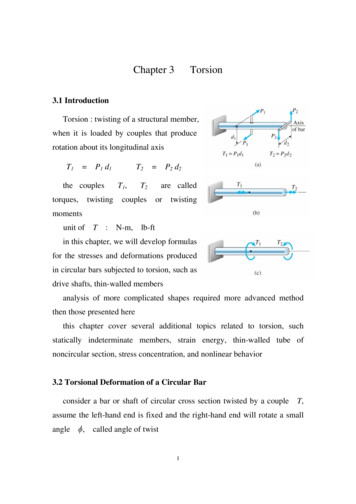
Chapter 3Torsion3.1 IntroductionTorsion : twisting of a structural member,when it is loaded by couples that producerotation about its longitudinal axisT1 P1 d1T1,the couplestorques,T2twisting P2 d2T2couplesare calledortwistingmomentsunit ofT:N-m,lb-ftin this chapter, we will develop formulasfor the stresses and deformations producedin circular bars subjected to torsion, such asdrive shafts, thin-walled membersanalysis of more complicated shapes required more advanced methodthen those presented herethis chapter cover several additional topics related to torsion, suchstatically indeterminate members, strain energy, thin-walled tube ofnoncircular section, stress concentration, and nonlinear behavior3.2 Torsional Deformation of a Circular Barconsider a bar or shaft of circular cross section twisted by a coupleT,assume the left-hand end is fixed and the right-hand end will rotate a smallangle,called angle of twist1
if every cross section has the same radius and subjected to the sametorque, the angle(x) will vary linearly between endsunder twisting deformation, it is assumed1. plane section remains plane2. radii remaining straight and the cross sections remaining plane andcircular3. ifis small, neither the length Lconsider an element of the barsmall elementdx,nor its radius will changeon its outer surface we choose anabcd,during twisting the element rotate a small angle d ,a state of pure shear, and deformed intomax b b'CC abrdCCdx2ab'c'd,the element is inits shear strainmaxis
d / dxrepresents the rate of change of the angle of twist d / dx, denoteas the angle of twist per unit length or the rate of twist, then maxrin general,andpure torsion,are function ofx,in the special case ofis constant along the length (every cross section issubjected to the same torque) CLthenmax rCCLand the shear strain inside the bar can be obtained Crmaxfor a circular tube, it can be obtainedminr1 Cr2maxthe above relationships are based only upon geometric concepts, they arevalid for a circular bar of any material, elastic or inelastic, linear or nonlinear3.3 Circular Bars of Linearly Elastic Materialsshear stressin the bar of alinear elastic material is GG : shear modulus of elasticity3
with the geometric relation of the shear strain, it is obtainedmax and GrG Crmaxin circular bar vary linear with the radial distancethe center, the maximum valuesmaxandmaxfromoccur at the outer surfacethe shear stress acting on the plane of thecross section are accompanied by shearstresses of the same magnitude acting onlongitudinal plane of the barif the material is weaker in shear onlongitudinal plane than on cross-sectionalplanes, as in the case of a circular bar made of wood, the first crack dueto twisting will appear on the surface in longitudinal directiona rectangular element with sides at 45 o tothe axis of the shaft will be subjected totensile and compressive stressesThe Torsion Formulaconsider a bar subjected to pure torsion,the shear force acting on an elementisdAdA, the moment of this force aboutthe axis of bar isdM dAdA4
equation of moment equilibrium dMT A Gin whichIpA2 2dA G A[IpIp GdA GA]dAis the polar moment of inertiad4CC32for circular cross sectionAr4CC2 the above relation can be written TCCG IpG Ip : torsional rigiditythe angle of twist Lcan be expressed asTLCCG Ip torsional flexibilitytorsional stiffnessfkis measured in radiansL CCG IpG Ip CCLand the shear stress is G Gthe maximum shear stressTCCG Ipmax at5TCCIp ris2dA
maxTrCC Ip16 TCCd3for a circular tube(r24 - r14) / 2 Ip(d24 - d14) / 32if the hollow tube is very thinjIp(r22 r12) (r2 r1) (r2 - r1) / 2(2r2) (2r) (t) r3 t 2d3 t / 4limitations1. bar have circular cross section (either solid or hollow)2. material is linear elasticnote that the above equations cannot be used for bars of noncircularshapes, because their cross sections do not remain plane and their maximumstresses are not located at the farthest distances from the midpointExample 3-1a solid bar of circular cross sectiond 40 mm,L 1.3 m,max,(a) T 340 N-m,(b)all 42 MPa,(a) max Ip all16 TCCd3d4 / 32TLCCG Ip G 80 GPa 2.5o, ?T ?16 x 340 N-MCCCCCCC(0.04 m)3 27.1 MPa2.51 x 10-7 m4340 N-m x 1.3 mCCCCCCCCCC 80 GPa x 2.51 x 10-7 m460.02198 rad 1.26o
(b) due tod3T1 due toT2 42 MPaallall G Ip thus2.5o all(0.04 m)3 x 42 MPa / 16 528 N-m/ 16 all rad / 180o 0.04363 rad2.5 x80 GPa x 2.51 x 10-7 m4 x 0.04363 / 1.3 m/L 674 N-mTall min [T1, T2] 528 N-mExample 3-2a steel shaft of either solid bar or circular tubeTall 1200 N-m,all 40 MPa0.75o / mG 78 GPa(a) determined0 of the solid bar(b) for the hollow shaft, t d2 / 10, determine d2(c) determine d2 / d0,Whollow / Wsolid(a) for the solid shaft, due tod 03d0due toIpd 04d0 16 T / all 40 MPa 16 x 1200 /0.0535 m all 32 Ip /40 152.8 x 10⁻⁶ m353.5 mm0.75o / m 0.75 x T/G all allrad / 180o / m 0.01309 rad / m 1200 / 78 x 109 x 0.01309 117.5 x 10⁻⁸ m4 32 x 117.5 x 10-8 /0.0588 m 1197 x 10-8 m458.8 mmthus, we choose d0 58.8 mm[in practical design, d0 60 mm](b) for the hollow shaftd1 d2 -2t d2 -70.2 d2 0.8 d2
(d24 - d14) / 32all 40 MPa 0.05796 d24 Ipdue toIpd 23 d2due to0.0637 m all d2 all1200 (d2/2) / 4063.7 mm0.75o / m 0.01309d 24Tr/ 0.05796 d24258.8 x 10-6 m3 all[d24 - (0.8d2)4] / 32 0.01309 rad / m 1200 / 78 x 109 x 0.05796 d24 T / G Ip2028 x 10-8 m4 0.0671 m 67.1 mmthus, we choose d0 67.1 mm[in practical design, d0 70 mm](c) the ratios of hollow and solid bar ared2 / d0 67.1 / 58.8WhollowCCC WsolidAhollowCCCAsolid 1.14(d22 - d12)/4CCCCCCd02/4 0.47the hollow shaft has 14% greater in diameter but 53% less in weightExample 3-3a hollow shaft and a solid shaft has samematerial, same length, same outer radiusandri R,0.6 R for the hollow shaft(a) for same T, compare their , , and W(b) determine the strength-to-weight ratio(a) T R / Ip the ratio of(Ip)H R2 /2 or-T L / G Ipis the ratio of 1 / Ip(0.6R)2 /28 0.4352R2
(Ip)SR2 /2 (Ip)S / (Ip)H R20.50.5 / 0.4352 thus1 H/also2 H/3 WH / WS AH / AS Sthe hollow shaft has1.15 (Ip)S / (Ip)H 1.15 (Ip)S / (Ip)H1.15S15% [R2 - (0.6R)2] /greater inandR2 0.64,butdecrease in weight(b) strength-to-weight ratioTH TS max Ipmax Ip WH/Rmax R4) / R 0.4352(0.5R 4) / R maxWSSH TH / WH SS TS / WSis36%Tall / W(0.4352R2 L0.64thusSH/R S0.68 0.5R2 L maxmaxgreater than SS3.4 Nonuniform Torsion(1) constant torque through each segmentTCD - T1- T2 TBC - T1- T2TAB ni 1i T3 - T1T i LiCCi 1Gi Ipin(2) constant torque with continuouslyvarying cross section9R/ LR/ L0.5R3R3maxmax36%
T dx CCCG Ip(x)dT dx CCC0G Ip(x)LL d 0(3) continuously varying cross section andcontinuously varying torqueT(x) dxL CCC0G Ip(x)L d 0Example 3-4a solid steel shaft ABCDE, d 30 mmT1 275 N-m T2 450 N-mT3 175 N-m G 80 GPaL1 500 mm L2 400 mmdeterminein each part andmaxTCD T2TBC - T1-T1 BC16 TBC CCCd3CD 16 TCDCCCd3BD IpBC d4CC32BD175 N-m- 275 N-m 16 x 275 x 103CCCCCC303 16 x 175 x 103CCCCCC303 33 MPa51.9 MPaCD 304CCC3210 79,520 mm2
BC - 275 x 103 x 500CCCCCCCC80 x 103 x 79,520CDTCD L2 CCC G Ip175 x 103 x 400CCCCCCCC80 x 103 x 79,520BD TBC L1CCCG Ip BC - 0.0216 rad 0.011 rad - 0.0216 0.011 - 0.0106 rad - 0.61oCDExample 3-5a tapered barABof solid circularcross section is twisted by torque Td dAat A,determine(a)Tmax thusmaxd dB dAat B, dBandof the barconstant over the length,max occurs at dmin [end A]16 TCCCdA3(b) angle of twistthen d(x) dAIp(x)d4 CC32dB - dACCC xL C (dA32 dB - dA 4CCC x)LT dx32 TdxLL CCC CC CCCCCCC00G Ip(x)GdB - dA 4(dA CCC x)Lto evaluate the integral, we note that it is of the form11
dx CCCC(a bx)4if we chooseofa1- CCCCC3 b (a bx)3 dAandb (dB - dA) / L,then the integralcan be obtained 32 T L1CCCCCC ( CC3 G(dB - dA)dA3-1CC )dB3a convenient form can be written where2 1TLCCC ( CCCCC )G IpA3 3 dB / dAIpAdA4 / 32 in the special case of a prismatic bar,3.5 Stresses and Strains in Pure Shearfor a circular bar subjected to torsion,shear stresses act over the cross sectionsand on longitudinal planesan stress elementabcdis cutbetween two cross sections and betweentwo longitudinal planes, this element is in astate of pure shearwe now cut from the plane stresselement to a wedge-shaped element, denoteA0the area of the vertical side face, thenthe area of the bottom face isA0 tan ,12 1,then T L / G Ip
and the area of the inclined face isA0secsumming forces in the direction ofA0 sec orA0 sin2 sin A0 tan sin 2coscossumming forces in the direction ofA0 sec orand (cos2A0 cos- sin2 )vary with-A0 tan is plotted in figure( )max at 0o( )min -at ! 90o( )max !at ! 45othe state of pure shear stress isequivalent to equal tensile and compressivestresses on an element rotation through anangle of 45oif a twisted bar is made of material thatis weaker in tension than in shear, failurewill occur in tension along a helix inclinedat 45o, such as chalkStrains in pure shearif the material is linearly elastic cos 2/G13sin
where Gis the shear modulus of elasticityconsider the strains that occur in anelement oriented at 45o,applied at 45o andmin - 45oapplied at 45othen atmaxCCE max - 45oat - max minCCE CE- - (1 ) / Emax CCE C (1 )Eit will be shown in next section the following relationshipC2 maxExample 3-6a circular tube with do 80 mm,T 4 kN-mG di 60 mm27 GPadetermine (a) maximum tensile, compressiveand shear stresses(a)(b) maximum strainsthe maximum shear stress is maxTrCCIp 4000 x 0.04CCCCCCCCC 58.2 MPaC [(0.08)4 - (0.06)4]32the maximum tensile and compressive stresses aret 58.2 MPaat - 45oc - 58.2 MPaat 45o14
(b)maximum strains maxmax/G 58.2 / 27 x 103 0.0022the maximum normal strains is maxi.e.max t/2 0.0110.011c - 0.0113.6 Relationship Between Moduli of ElasticityE,Gandan important relationship betweenE,Gandcan be obtainedconsider the square stress elementabcd,with the length of each sidedenoted ash,shear stress, subjected to purethen/Gthe length of diagonalis 2 h,bdafter deformationLbd 2 h (1 max)using the law of cosines for2Lbd abdh2 h2 - 2 h2 cos ( C ) 2152 h2 [ 1 - cos ( C )]2
then(1 thus1 max) 22 max1 - cos ( C )2 2maxis very small, thenmax 2max 1 0,1 sinsinand sinthe resulting expression can be obtainedwithmax /2max (1 ) / Eand /Gthe following relationship can be writtenGthusECCCC2 (1 ) E,Gandare not independent properties of a linear elasticmaterial3.7 Transmission of Power by Circular Shaftsthe most important use of circular shafts is to transmit mechanical power,such as drive shaft of an automobile, propeller shaft of a ship, axle of bicycle,torsional bar, etc.a common design problem is the determination of the required size of ashaft so that it will transmit a specified amount of power at a specified speedof revolution without exceeding the allowable stressconsider a motor drive shaft, rotating at angular speedtransmitting a torqueW TT,the work done is[T is constant for steady state]16,it is
whereis angular rotation in radians, ant the power is dW / dtP dWCCdt 2f P 2fTdenotenthusP dT CCdtf T:is frequency of revolutionrad / sf : Hz s-1the number of revolution per minute (rpm), then n 60 f2n TCCCC60(n rpm, T N-m, P W)in U.S. engineering practice, power is often expressed in horsepower (hp),1 hp 550 ft-lb / s,thus the horsepower Hbeing transmitted by arotating shaft isH2n TCCCC60 x 550 2n TCCCC33,000(n rpm, T lb-ft, H hp)1 hp 550 lb-ft/s 550 x 4.448 N x 0.305 m/s 746 N-m / s 746 W (W : watt)Example 3-7P 30 kW,all 42 MPa(a)n 500 rpm,determined(b)n 4000 rpm, determined(a)Tmax60 PCCC2 n 16 TCCd3 60 x 30 kWCCCCC2 x 500 573 N-m16 x 573 N-m16 Td 3 CCC CCCCCC 69.5 x 10⁻⁶ m3x 42 MPaall17
(b)d 41.1 mmT 60 PCCC2 n16 Td 3 CC60 x 30 kWCCCCC2 x 4000 16 x 71.6 N-mCCCCCCCx 42 MPa alld 71.6 N-m 8.68 x 10⁻⁶ m320.55 mmthe higher the speed of rotation, the smaller the required size of the shaftExample 3-8a solid steel shaft ABC,motorAPB35 kW, PC transmitdetermineTAmaxd 50 mm50 kW at10 Hz15 kWandAC,G PA50 x 103 CC CCCC 2 f2 1080 GPa796 N-msimilarly PB 35 kN TB 557 N-mPCthen 15 kNTCTAB 796 N-m 239 N-mTBC 239 N-mshear stress and angle of twist in segment ABAB 16 TABCCCd3 16 x 796CCCC503ABTAB LAB CCCG Ip 796 x 1.0CCCCCCC 32.4 MPa80 x 109 C 0.0543218 0.0162 rad
shear stress and angle of twist in segment BCBCAB 16 TBC16 x 239 CCC CCCC 9.7 MPad3503239 x 1.2TBC LBC CCC CCCCCCC 0.0058 radG Ip80 x 109 C 0.05432max ABAC AB 32.4 MPa BC 0.0162 0.0058 0.022 rad 1.26o3.8 Statically Indeterminate Torsional Memberstorsional member may be statically indeterminate if they are constrainedby more supports than are required to hold them in static equilibrium, or thetorsional member is made by two or more kinds of materialsflexibility and stiffness methods may be usedonly flexibility method is used in the laterdiscussionconsider a composite barABfixed atthe end plate rotates through an angleT1andT2are developed in thesolid bar and tube, respectivelyequation of equilibriumT1 T2 Tequation of compatibility1 2torque-displacement relations19A
T1 L CCCG1 Ip112T2 L CCCG2 Ip2then the equation of compatibility becomesT1 LCCCG1 Ip1 T2 LCCCG2 Ip2now we can solve for T1and T1andT2G1 Ip1T ( CCCCCC ) T2G1 Ip1 G2 Ip2 G2 Ip2T ( CCCCCC )G1 Ip1 G2 Ip2TLCCCCCCG1 Ip1 G2 Ip2Example 3-9a barT0ACBis fixed at both endsis applied at pointAC: dA,LA,IpACB: dB,LB,IpBdetermineC(a) TA, TB (b)AC,equation of equilibriumTA TB T0equation of compatibility1 2 0torque-displacement equations1 T0 LA / G IpA20CB(c)C
2 TB LA- CCCG IpATB LBCCCG IpB-then the equation of compatibility becomesT 0 LACCCG IpA-TA and TBTA TB LACCCG IpATALB IpAT0 ( CCCCCC )LB IpA LA IpB IpACB T0 LBCCLTA dA CCC2 IpATB dB CCC2 IpBACCif the bar is prismatic,thenC0LA IpBT0 ( CCCCCC )LB IpA LA IpBIpT0 LACCL and BCareT0 LB dACCCCCCC2 (LB IpA LA IpB)T0 LA dB CCCCCCC2 (LB IpA LA IpB) angle of rotation at section CT A LA CCCG IpATBIpB TBmaximum shear stress inAC can be solvedif the bar is prismatic,thenTB LBCCCG IpB- isTB LBCCCG IpAIpA IpB T 0 LA L B CCCCG L Ip21T0 LA LBCCCCCCCG (LB IpA LA IpB)Ip
3.9 Strain Energy in Torsion and Pure Shearconsider a prismatic barsubjected to a torqueT,ABthe bartwists an angleif the bar material is linear elastic,then the strain energy U of the bar isU W thenU T/2 T L / G Ip T2 LCCC2 G IpG Ip 2CCC2L if the bar is subjected to nonuniform torsion, thenU nUii 1Ti 2 L i CCCi 12 Gi Ipinif either the cross section or the torque varies along the axis, then[T(x)]2 dxdU CCCC2 G Ip(x)U strain energy density in pure shearconsider a stressed element with eachside having lengthhunder shear stressthe shear force VV and thickness t,with shear strainisht22 dU[T(x)]2 dx CCCC02 G Ip(x)L
and the displacement ishfor linear elastic material, strain energy stored in this element isU WVCC2 and the strain energy densityu 2/2 /2Guh2 tCCC2 GU / per unit volume, then2/2Example 3-10a solid circular bar(a) torqueTaABof length Lacting at the free end(b) torque Tb acting at the midpoint(c) bothTaandTbactingsimultaneouslyTa 100 N-mL 1.6 mTb 150 N-mG 80 GPaIp 79.52 x 103 mm4determine the strain energy in each case(a)Ta2 LCCC 2 G IpUa (b)Ub Tb2 (L/2)CCCC2 G Ip1002 x 106 x 1.6 x 103CCCCCCCCCCC2 x 80 x 103 x 79.52 x 103 Tb 2 LCCC4 G Ip23 2.83 J 1.26 J (N-m)
(c)Ti2 Li CCCi 12 Gi IpinUcTa2 L CCC2 G Ip 1.26 J Note that (c) Ta2 (L/2)CCCC2 G IpTa T b LCCCC2 G Ip1.89 J (Ta Tb)2 (L/2) CCCCCC2 G IpTb2 LCCC4 G Ip 2.83 Jis not equal to (a) (b),5.98 Jbecause UiExample 3-11a prismatic barABis loaded by adistributed torque of constant intensitytper unit distancet G480 lb-in/in L 12 ft11.5 x 106 psi Ip 18.17 in4determine the strain energyT(x) tx[(tx)]2 dx CCCC 02 G IpLU 1LCCC (tx)2 dx2 G Ip 04802 x (12 x 12)3 CCCCCCCCC6 x 11.5 x 106 x 17.18 Example 3-12a tapered barABof solid circularcross section is supported a torque Td dAdeterminei dB from left to rightAby energy method24580 in-lb t2 L 3CCC6 G IpT2
W T ACC24 C [d(x)]32Ip(x)C ( dA32 dB - dA 4CCC x )L[T(x)]2 dx16 T2 Ldx 0 CCCC CC 0 CCCCCCC2 G Ip(x)GdB - dA4( dA CCC x )LLU 16 T2 L1 CCCCCC ( CC3 G (dB - dA)dA3withUA W,thenA-1CC )dB3can be obtained32 T L1CCCCCC ( CC3 G (dB - dA)dA3same result as in example 3-53-10 Thin-Walled Tubes3-11 Stress Concentrations in Torsion3-12 Nonlinear Torsion of Circular Bars25-1CC )dB3
3 d& / dx represents the rate of change of the angle of twist &, denote d& / dx as the angle of twist per unit length or the rate of twist, then max r in general, & and are function of x, in the special case of pure torsio