Transcription
PLC 2/17 and PLC 5 ProgrammableController Memory Modules(Cat. Nos. 1785-MJ and 1785-MK)Installation DataTo the InstallerThis document provides you with the following information:What this memory module package containsInstalling an EEPROMCompatibilityHandling the EEPROM moduleSetting backplane switchesUsing the write enable jumperInstalling the EEPROM moduleRemoving an EEPROMWriting to an EEPROMPLC-5 EEPROM memory cartridge compatibilityCorrecting incompatibilityRestoring a program from an EEPROMSpecificationsWhat this Memory ModulePackage ContainsYour memory module package should contain one of the followingmemory modules with a write enable jumper installed on the memorymodule:Cat. No. 1785-MJ (8K words)Cat. No. 1785-MK ((16K words)
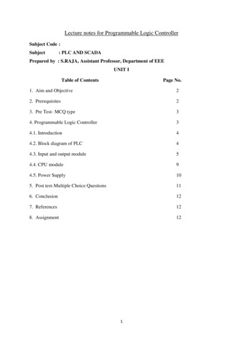
Installation DataEEPROM Memory Modules(Cat. Nos. 1785 MJ and 1785 MK)CompatibilityTable 1 shows the programmable controllers and the software that arecompatible with the 1785-MJ and 1785-MK EEPROM modules.Table 1EEPROM Module CompatibilityEEPROM Module1785 MK1785 MJHandling the EEPROM ModuleCompatible ProgrammableControllersCompatible Software1772 LW (PLC 2/17)1772 LWP (PLC 2/17)1785 LT (PLC 5/10)1785 LT2 (PLC 5/12)1785 LT3 (PLC 5/15)1785 LT4 (PLC 5/25)6200 Programming SoftwareThe Allen-Bradley EEPROM Modules (Cat. No. 1785-MJ, -MK) areshipped in a static-shielded bag to guard against electrostatic damage.Observe the following precautions when handling the module.WARNING: Under some conditions, electrostatic dischargecan degrade performance or damage the EEPROM module.Observe the following precautions to guard against electrostaticdamage.Touch a grounded object to rid yourself of static charge before handlingthe module.When not in use, keep the module in its static-shielded bag.Setting Backplane SwitchesSet the I/O chassis backplane switches before you install the PLC-2/17 orPLC-5 programmable controllers. Use a ballpoint pen to set each switch.(Do not use a pencil because the tip can break off and short the switch.)Use the following figure and Table 2, pg. 3 to select the mode of memorytransfer at power-up.ON (Closed)OFF (Open)Backplane switchesBackplaneSwitches218594
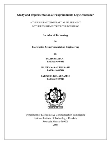
Installation DataEEPROM Memory Modules(Cat. Nos. 1785 MJ and 1785 MK)Table 2Selecting mode of memory transfer and switch settingsIf you want:Then set switch 6:Then set switch 7:EEPROM memory to transfer to processor memory at every power upOFFOFFEEPROM memory to transfer to processor memory at every power upOFFONEEPROM memory to transfer to processor memory when a defect isdetected in existing processor memoryONONEEPROM memory not to transfer to processor memory when a defect isdetected in existing processor memory (a processor fault occurs)ONOFFUsing the Write Enable JumperThe position of the write enable jumper determines whether data can bewritten to the EEPROM. The jumper can either be placed in the EEPROMor removed from the EEPROM and stored in a safe place of your choicefor future use. See Table 3 for more information on positioning the writeenable jumper.Table 3Using the Write Enable JumperIf the Enable Jumper is:Then a program:positioned on top of the two pins in the EEPROMcan be written to the EEPROMremoved from the two pins in the EEPROMcannot be written to the EEPROMThe EEPROM modules are packaged with the jumper in the position towrite to the EEPROM.Write EnableJumperCatalogLabelTo remove or insert the write enable jumper into the EEPROM module usea pair of needle nose pliers.Publication 1785-2.7 - October 198P/N 955109-67Printed in USA3
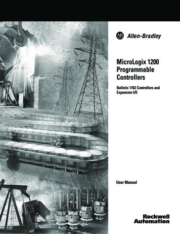
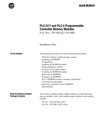
Installation DataEEPROM Memory Modules(Cat. Nos. 1785 MJ and 1785 MK)Installing an EEPROM Moduleinto the ProcessorInsert the EEPROM module into the bottom of the PLC-2/17 or PLC-5processor by following these steps:1.Turn off power to the I/O chassis and processor.CAUTION: Do not insert or remove the EEPROM underpower. Insertion or removal under power can result in loss ofprogram memory and a processor fault.2.Lift the latch of the I/O chassis that holds the processor and removethe processor from the chassis. Place the processor on a clean flatsurface with the bottom of the module facing you.3.Gently but firmly push the EEPROM into the processor until thebottom flange of the EEPROM is flush with the bottom of theprocessor.CatalogLabel12 07 7Removing an EEPROM Modulefrom the ProcessorRemove the EEPROM module by following these steps:1.Turn off power to the I/O chassis and processor.CAUTION: Do not insert or remove the EEPROM underpower. Insertion or removal under power can result in loss ofprogram memory.4
Installation DataEEPROM Memory Modules(Cat. Nos. 1785 MJ and 1785 MK)2.Lift the latch of the I/O chassis that holds the processor and removethe processor from the chassis. Place the processor on a clean flatsurface with the bottom of the module facing you.3.Using a coin or screwdriver blade, pry the EEPROM module out farenough to grasp the bottom flange of the EEPROM with your fingers.187424.Writing to an EEPROMRemove the EEPROM module.You can store a program on your EEPROM module if it is installed in yourprocessor. The procedure for writing to an EEPROM is different for eachtype of processor. Refer to the instructions that correspond with the type ofprocessor you are using.Using a Mini PLC 2/17, (Series A, B or C) ProcessorImportant: To avoid overriding the program you have on the processoryou must set the I/O chassis backplane switches so that EEPROM memorydoes not transfer at power-up. See Table 2, pg. 3 for more information onsetting backplane switches.Publication 1785-2.7 - October 1981.Insert the EEPROM into the processor by following the installationprocedure on pg. 4 in this document.2.Replace the processor into the I/O chassis and turn on power.3.Select the PROGRAM or REM PROGRAM mode on the front panelof the processor module.4.Use online programming to store data table values that you wantactivated when the processor transfers EEPROM back-up memory toprocessor memory. If this is not done the transition will occur withstart-up data table values.P/N 955109-67Printed in USA5
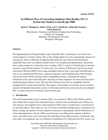
Installation DataEEPROM Memory Modules(Cat. Nos. 1785 MJ and 1785 MK)5.To transfer a duplicate of your program to the EEPROM,momentarily flip the MEMORY STORE switch on the processor tothe ON position until the PROC RUN indicator on the front of theprocessor is illuminated. Refer to Table 4 for an explanation ofindicator colors.MEMORYSTOREswitch18744Table 4Interpreting the PROC RUN IndicatorIf PROC RUN indicator is:Then:Solid greenThe program is being transferred and the indicatorwill turn off when the transfer is completeSolid redThere is an error and the indicator will stayilluminatedHandling an Error: Mini PLC-2/17If an error occurs during a write to the EEPROM check to see that thefollowing procedures have been completed:the processor is in the PROG or REM PROGRAM mode.the write protection jumper is seated correctly in the EEPROM.Reset the fault by cycling power to the processor.After the processor successfully writes to the EEPROM, do the following:61.Turn off power to the processor and I/O chassis.2.Remove the processor from the I/O chassis and remove the EEPROMby following the removal procedure in this document.3.Remove the write enable jumper from the EEPROM memory moduleto guard against unauthorized changes. Store the jumper in a safeplace for future use.
Installation DataEEPROM Memory Modules(Cat. Nos. 1785 MJ and 1785 MK)4.Use the space provided to label your EEPROM with a ballpoint pen.5.Set I/O chassis backplane switches so that EEPROM memorytransfers at power-up. For more information see the SettingBackplane Switches section, pg. 2 in this document.6.Re-install the EEPROM into the processor by following theinstallation procedure in this document.7.Re-install the processor into the I/O chassis.Using a PLC 2/17, (Series D) ProcessorImportant: To avoid overriding the program you have on the processoryou must set the I/O chassis backplane switches so that EEPROM memorydoes not transfer at power-up. See Table 2, pg. 3 for more information onsetting backplane switches.Publication 1785-2.7 - October 1981.Insert the EEPROM into the processor by following the installationprocedure on pg. 4 in this document.2.Replace the processor into the I/O chassis and turn on power.3.Select the PROGRAM or REM PROGRAM mode on the front panelof the processor module.4.Use online programming to store data table values that you wantactivated when the processor transfers EEPROM back-up memory toprocessor memory. If this is not done the transition will occur withstart-up data table values.P/N 955109-67Printed in USA7
Installation DataEEPROM Memory Modules(Cat. Nos. 1785 MJ and 1785 MK)5.Quickly, turn the mode select key switch to the MEMORY STOREposition, then to the PROGRAM position and then back to theMEMORY STORE position.MEMORYSTOREkey switch6.18745Check to see that the PROC RUN indicator on the front of theprocessor is illuminated. Refer to Table 5 for an explanation ofindicator colors.Table 5Interpreting the PROC RUN IndicatorIf PROC RUN indicator is:Then:Solid greenThe program is being transferred and the indicatorwill turn off when the transfer is completeSolid redThere is an error and the indicator will stayilluminatedHandling an Error: Mini PLC-2/17, (Series D) ProcessorIf an error occurs during a write to the EEPROM check to see that :the processor is in the PROG or REM PROGRAM mode.the write enable jumper is seated correctly in the EEPROM.Reset the fault by cycling power to the processor.After the processor successfully writes to the EEPROM, do the following:81.Turn off power to the processor and I/O chassis2.Remove the processor from the I/O chassis and remove the EEPROMby following the removal procedure in this document.
Installation DataEEPROM Memory Modules(Cat. Nos. 1785 MJ and 1785 MK)3.Remove the write enable jumper from the EEPROM memory moduleto guard against unauthorized changes. Store the jumper in a safeplace for future use.4.Use the space provided to label your EEPROM with a ballpoint pen.5.Set I/O chassis backplane switches so that EEPROM memorytransfers at power-up. For more information see the SettingBackplane Switches section in this document.6.Re-install the EEPROM into the processor by following theinstallation procedure in this document.7.Re-install the processor into the I/O chassis.Using a PLC 5/10, 5/12, 5/15 or 5/25 ProcessorImportant: To avoid overriding the program you have on the processoryou must set the I/O chassis backplane switches so that EEPROM memorydoes not transfer at power-up. See Table 2, pg. 3 for more information onsetting backplane switches.1.Insert the EEPROM into the processor by following the installationprocedure on pg. 4 in this document.2.Replace the processor into the I/O chassis and turn on power.3.Select the PROGRAM or REM PROGRAM mode on the front panelof the processor module.4.Use online programming to store data table values that you wantactivated when the processor transfers EEPROM back-up memory toprocessor memory. If this is not done the transition will occur withstart–up data table values.5.Start on the Ladder Editor main menu to begin transfer of yourprogram to the EEPROM.Press [F7] - General UtilityThe system displays the General Utility screen.Press [F8] - Write EEPROMPublication 1785-2.7 - October 198P/N 955109-67Printed in USA9
Installation DataEEPROM Memory Modules(Cat. Nos. 1785 MJ and 1785 MK)The system will ask you to confirm your selection.Type one of the following:[Y] [Enter] or [F8] for yes[N] [Enter] or [F10]for no[Esc] to exit the write procedureIf you confirm the procedure, the EEPROM write begins.During this procedure, the “PROC” LED on the processorflashes and the programming terminal beeps until the writeprocedure completes.If no error occurs during the write to the EEPROM, the systemdisplays the following message:EEPROM SUCCESSFULLY BURNEDAfter the processor successfully writes to the EEPROM, do the following:1.Turn off power to the processor and I/O chassis2.Remove the processor from the I/O chassis and remove the EEPROMby following the removal procedure in this document.3.Remove the write enable jumper to guard against unauthorizedchanges. Store the jumper in safe place for future use.4.Use the space provided to label your EEPROM with a ballpoint pen.5.Set I/O chassis backplane switches so that EEPROM memorytransfers at power–up. For more information see the SettingBackplane Switches section in this document.6.Re-install the EEPROM into the processor by following theinstallation procedure in this document.7.Re-install the processor into the I/O chassis.Handling an Error:Mini PLC -5/10, -5/12, -5/15 or -5/25 ProcessorIf an error occurs during a write to the EEPROM, the system displays thefollowing message:EEPROM NOT BURNEDIf unsuccessful, review the PLC-5/10, -5/12, -5/15, -5/25 procedure forwriting to an EEPROM and repeat it from the beginning.10
Installation DataEEPROM Memory Modules(Cat. Nos. 1785 MJ and 1785 MK)PLC 5 EEPROM MemoryCartridge CompatibilityWhen using a 1785-MJ or 1785-MK EEPROM to transfer programsbetween PLC-5 family processors, check compatibility between theprocessors. Some series/revision processor combinations are incompatible,regardless of EEPROM. Refer to the Table below for cartridgecompatibility.Check compatibility by comparing the series/revision levels of the“burned one” and “loaded into” processors in Table 6 where:Y compatibleN incompatibleN* incompatible with LED indicationNewer processors indicate transport incompatibility (shown by * inTable 6) by:Flashing PROC LEDSetting bit 09 in word 11 of the processor status fileThese indications only occur when the processor attempts to transfer theprogram from EEPROM to processor RAM at power up or after theprocessor has detected its RAM is invalid.Table 6EEPROM and PLC 5 Processor CompatibilityCartridge BurnedCartridge Loaded IntoPLC 5/10Series APLC 5/12Series APLC 5/15Series APLC 5/15Series BPLC 5/25Series AProcessorSer/Rev A/A A/A A/H A/K B/E B/FA/A A/BPLC 5/10Series A A/AYYNN*YYNYPLC 5/12Series A A/AYYNN*YYNYPLC 5/15Series A A/H A/KN*N*N*N*YYYYNNN*N*NNNNPLC 5/15Series B B/E B/FYYYYNNN*N*YYYYNNYYPLC 5/25Series AA/A A/BNYNYNNN*N*NYNYYNNYFor processor combinations indicated by N* in the table, you can check forincompatibility by attempting to transfer the program from EEPROM toprocessor RAM. The PROC LED blinks if the combination isincompatible.Publication 1785-2.7 - October 198P/N 955109-67Printed in USA11
Installation DataEEPROM Memory Modules(Cat. Nos. 1785 MJ and 1785 MK)Correcting IncompatibilityBetween PLC 5 FamilyProcessorsCorrect incompatibility by replacing the EEPROM program (downloadedfrom another processor) with the program downloaded from its hostprocessor.To restore a processor memory file, do the following:1.Start on the Online Program Directory2.Press [F2] – Save/RestoreThe system displays the Save/Restore screen.3.Press [F4] – Restore ProgramThe system displays the Restore File window.4.Press [F8] – Select Type until the directory at the top of thefile window is the directory for .ACH files (processor memory files,also known as archive files).The default directory listing is for the .ACH files.5.Select the processor memory file you want to restore.Do one of the following to select the processor memory file you wantto restore:Use the arrow keys to place the cursor on the processor memoryfile you want.Type in the complete name of the processor memory file or apartial name or letter and press [Enter].6.Press [F1] – Begin OperationImportant: The system displays a message that the restore utility is beingloaded. You can stop the process with [F3] – Abort Utility. If youpress [F3] – Abort Utility to cancel the restore process thesystem clears processor memory and you lose any information that wasthere.When communication is established, the top part of the status screendisplays the processor address and file name. The remainder of thestatus screen displays messages about the restore procedure.You will see a message and prompt displayed if :the processor is in REMOTE, RUN or TEST modethe file is too large to restore to available memory12
Installation DataEEPROM Memory Modules(Cat. Nos. 1785 MJ and 1785 MK)The message and prompt will be displayed as follows:The processor will be put in REMOTE PROGRAM.Press F8 to abort, F10 to continue.Press [F8] – Abort to stop the save or [F10] –to continue the save.7.ContinueWhen the restore process finishes, press any key to return to theOnline Program Directory screen.If you started the restore procedure in REMOTE, RUN, or TESTmode, the software prompts you whether you want to return to themode in which the processor started.Important: Early PLC-5 processors set a fault when you restore processormemory files. The fault prevents you from accidentally placing theprocessor in RUN mode while the restore occurs. Once the completeprocessor memory file is restored, the system clears the fault and the faultLED stops flashing.8.Restoring a Program from anEEPROMTransfer a copy of your program to the EEPROM. Use the procedurein this document for transferring a copy of your program to anEEPROM using a PLC-5/10, -5/12,-5/15, or -5/25 processor.Use the following procedure to restore the program saved on yourEEPROM to a processor. The procedure is the same for the compatibleprocessors.Important: We recommend that you check compatibility beforetransporting programs between PLC-5 family processors. Refer to thesection on PLC-5 EEPROM Memory Cartridge Compatibility, pg. 11 inthis document.Publication 1785-2.7 - October 1981.Check that the processor’s back-up lithium battery is installed and itsexpiration date has not passed.2.Turn off power to the I/O chassis and processor.3.Insert the EEPROM into the processor using the installationprocedure in this document.4.Set switches 6 and 7 of the switch assembly group on the I/O chassisbackplane to the OFF position.P/N 955109-67Printed in USA13
Installation DataEEPROM Memory Modules(Cat. Nos. 1785 MJ and 1785 MK)ON (Closed)OFF (Open)Backplane switchesset to OFF.BackplaneSwitches5.Insert the processor into the I/O chassis.6.Turn on power to the processor. Program transfer and executionbegin immediately if the processor is in RUN, RUN/PROG, orREMOTE PROGRAM mode.SpecificationsCapacity8K words (1785 MJ)16K words (1785 MK)TypeNonvolatileSizeInches 2.18L x 1.73H x 0.69DMillimeters 55.4L x 43.9H x 17.4DEnvironmentalOperating Temperature140 to 60 C (32 to 140 F)Storage Temperature-40 to 85 C (-40 to 185 F)Relative Humidity5 to 95% (without condensation)
Installation DataEEPROM Memory Modules(Cat. Nos. 1785 MJ and 1785 MK)Publication 1785-2.7 - October 198P/N 955109-67Printed in USA15
Rockwell AutomationSupportRockwell Automation provides technical information on the Web to assist you in usingits products. At http://support.rockwellautomation.com, you can find technicalmanuals, a knowledge base of FAQs, technical and application notes, sample code andlinks to software service packs, and a MySupport feature that you can customize tomake the best use of these tools.For an additional level of technical phone support for installation, configuration, andtroubleshooting, we offer TechConnect support programs. For more information,contact your local distributor or Rockwell Automation representative, or ation AssistanceIf you experience a problem within the first 24 hours of installation, please review theinformation that's contained in this manual. You can also contact a special CustomerSupport number for initial help in getting your product up and running.United States1.440.646.3434Monday – Friday, 8am – 5pm ESTOutside UnitedStatesPlease contact your local Rockwell Automation representative for anytechnical support issues.New Product Satisfaction ReturnRockwell Automation tests all of its products to ensure that they are fully operationalwhen shipped from the manufacturing facility. However, if your product is notfunctioning and needs to be returned, follow these procedures.Publication 1785-2.7 - October 1989 20United StatesContact your distributor. You must provide a Customer Support casenumber (see phone number above to obtain one) to your distributor inorder to complete the return process.Outside UnitedStatesPlease contact your local Rockwell Automation representative for thereturn procedure.PN 955106-59Copyright 1989 Rockwell Automation, Inc. All rights reserved. Printed in the U.S.A.
Insert the EEPROM module into the bottom of the PLC-2/17 or PLC-5 processor by following these steps: 1. Turn off power to the I/O chassis and processor. CAUTION: Do not insert or remove the EEPROM under power. Insertion or removal under power can result in loss of program memory and a processor fault. 2.