Transcription
Addition of a larger nozzle to a pressure vesselNB members Meeting October 2019- R Ferrell1
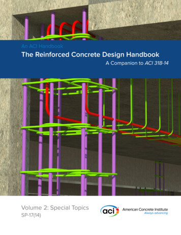
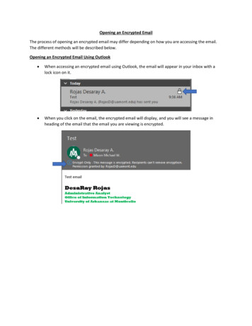
Reinforced OpeningWelded Nozzle Design PlanRemove an NPS 10 nozzle and replace with an NPS 12 nozzle2
Nozzle Alteration Plan Replace a NPS 10 outlet nozzle with a NPS 12 outletnozzle on a pressure vessel. This ASME Section VIII pressure vessel requirespostweld heat treatment. We will use NBIC Part 3paragraph 2.5.2 local PWHT or Welding Method 1. Contact your Repair Inspector to authorize thisalteration and discuss the alteration plan beforequoting the job.3
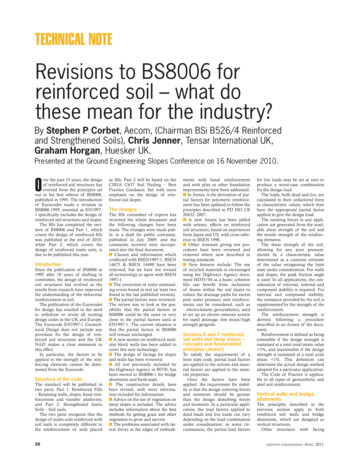
Alteration Nozzle4
Nozzle Alteration Plan Reinforcing calculations need to be done to determine nozzlethickness or the need for a reinforcing element. (UG-37)– This is done because the cylindrical shell is designed to carry hoopstress (circumferential stress) caused by internal pressure. Removingmetal by placing a hole in the cylinder disrupts the uniformdistribution of this membrane stress. Therefore, that metal must beput back (compensation) to absorb its share of the stress load. The shell thickness calculation needs to be done to determinethe required shell thickness before calculating available area. This shell is made up of one piece of plate. The nozzle is onthe top of the shell.5
Nozzle Alteration Plan(known information) P MAWP 700 psi Shell material is SA-516-70 (S 20,000 psi) with amaximum design temperature of 500 F and MDMTof 40 F. (see UCS-66) The Manufacturer’s Data Report from the NationalBoard shows a shell thickness of 1.625 inches, butthere is general corrosion pits 0.125 inches deepnear the nozzle reinforcement area. The originalinside diameter was 48 inches.6
Nozzle Alteration Plan(known information) The new nozzle is NPS 12 (12.75 inch outsidediameter), SA-106 Gr C, 0.562 inch nominal wall(SCH 60),S 20,000 psi, design temperature is 500 F Note:– when pipe is ordered and received using nominal wallthickness, a 12.5% under tolerance must be deductedfrom the wall for design calculations.– For example, 0.562 nominal x .875 (subtracts 12.5%) 0.492 inches7
Design Calculations Both the shell and nozzle are cylindrical componentsunder internal pressure. Therefore, we will use UG-27 (c) 1 to calculate theminimum required wall thickness for both.8
20 These formulas will govern only when the circumferential jointefficiency is less than one‐half the longitudinal jointefficiency, or when the effect of supplementary loadings (UG-22) causinglongitudinal bending or tension in conjunctionwith internal pressure is being investigated.9
UG-27 Shell Calculationt shellt shellPR SE (0.6) P700 24.125 20000 1 (0.6)700t shell16887.5 19580tshell 0.863”10 P 700 psiR 24.125″S 20,000psiE 1 full radiographyC 0 no additivethickness
UG-27 Nozzle CalculationPRt SE 0.6 P P 700 psi R 5.88325 (subtracted12 ½%)700 (5.88325) S 20,000 psi𝑡 20000 1 0.6 700 E 1 (seamless pipe) C 0 no additive4706.6thickness𝑡 16620trn 0.283"11
Minimum Nozzle Wall Thickness(see UG-45)The minimum nozzle wall thickness, other than access and inspection openings, shallbe not less than the following:This will result in theprevention of the usage ofthin wall nozzles. To join a thinwall item to a vessel, anintermediate fitting will benecessary12
ASME Section VIII UW-16.1 Welded NozzleSpecial RuleTYPICAL(b)(e)Necks abutting a vessel wall shall be attached by full penetration grooveweld [see (b) above]Necks inserted through the vessel wall may be attached by full penetrationgroove weld [see (e) above]Special rule controlling weld placement. In most cases it will result with a weld being placed at two points,the intersection of the nozzle on the outside of the vessel shell and at the intersection of the nozzle withthe inside of the shell. It is to eliminate an exposed crevice on the inside of the pressure vessel.13
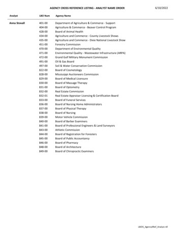
Minimum Nozzle Weld SizingDefined In UW-16 and Fig. UW-16.1Typical Example:Solve minimum weld sizes (UW-16.2 (b))also see UW-15 for minimum strengthtmin the smaller of ¾ in. or the thicknessof the thinner parts joined by a fillet,single bevel, or single j weldtctc not less than the smaller of ¼ in. or 0.7tmin (this is the throat dimension not leg)The nozzle is thinner than the shell so:tn 0.562 inch tmintc 0.7(tmin) 0.393 inchTherefore the minimum leg is .556 inch (9/16 inch)This is an important step in verification of the nozzle. Should this be done incorrectly, the nozzle couldfail. t minimum is a function of the two items being joined. Where reinforcing elements are involved,there will be more than one value of t minimum based on the weld being considered.14
Fillet Weld Throat VersusLeg DimensionsAcRight Angle Triangle(typical fillet weld shape)4590Ba c b22b45c a b22b c a2CaWeld throatAbCcWeld legaB15Weld leg Weld throat x 1.4142Weld throat weld leg/1.41422
Section VIII16
Section I17
Section IV18
FIG. UG-37.1tn 0.562 in.d 11.626 in.t 1.625 in.tr 0.863 in.F 1.0fr1 1Area of Reinforcement RequireddtnA dtrF 2tntrF(1-fr1)trA 11.625 x 0.863 x 1 0 10.032 0 10.032 in.219tIf Nozzle Sn 17,100 ( Sa -106-B)Then fr1 0.855 and A would be over12”.
FIG. UG-37.1Area of Reinforcement Available in Vesseldtntn 0.562 in.d 11.625 in.A1 d(E1t-Ftr)-2tn(E1t-Ftr)(1-fr1)t 1.625in.Ortr 0.863 in.A1 2(t tn )(E1t-Ftr)(1-fr1)F 1.0USE LARGER VALUEfr1 1E1 1trA1 8.85 in.220t
UG-37.1Area of Reinforcement Available in Nozzle External of VesseltrntndUse the smaller valuetn 0.562 in.A2 5(tn-trn) fr2 tnd 11.625 in.trn 0.2985 in.F 1.0fr2 0.855tA2 0.784 in.221
UG-37.1Area available in nozzle weldsdtntn 0.562 in.tc 0.398 in.fr2 0.855Weld leg 0.5625 in.A41 (leg)2 fr2tA41 0.270 in.222
UG-37.1Area of reinforcement available on inside nozzletidUse smaller valueFr2 sn/ss 1A3 2hti fr2A3 2 x 1.405 x 0.562 x 1thh, 2.5 t, 2.5ti3.875 , 4.0625, 1.40523A3 1.58 in2
Total Area of reinforcement availabletndthA1 A2 A3 A41 A2411.484 versus 10.032
25
26
27
Evaluate Weld StrengthUG-41(b)Verify strength of Compensation UG-37, UG-41, UW-15 b) 1 exempts sketches in UW-16.1 Our nozzle installation is equal to figure UW-16.1c) 28No further analysis required for weld loading as per UG-41
29
W is the requiredweld strength toattach elements thatare not an integralpart of the vessel wall30
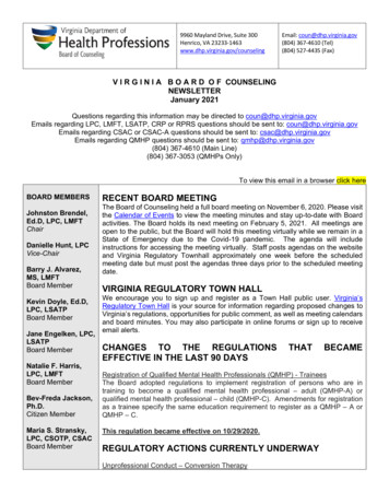
Exempt OpeningsReinforcement Calculation Exception– UG-36 exempts small openings in vessels not subject torapid fluctuations in pressure 3-1/2 in. (89 mm) diameter—in vessel shellsor heads with a required minimum thicknessof 3/8 in.(10 mm) or less; 2-3/8 in. (60 mm) diameter—in vessel shellsor heads over a required minimum thicknessof 3/8 in. (10 mm);31
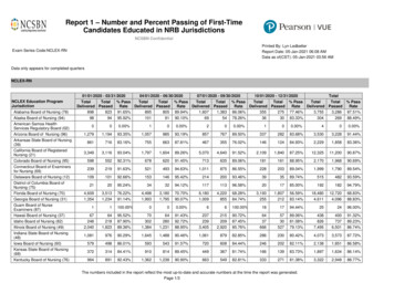
Exempt Openings (cont.) threaded, studded, or expanded connectionsin which the hole cut in the shell or head is notgreater than 2-3/8 in. (60 mm) diameter no two isolated unreinforced openings, inaccordance with above, shall have their centerscloser to each other than the sum of theirdiameters32
No centers closer to each other thanthe sum of their diametersLess than or equal to 5 inches3 inch dia.332 inch dia.
PWHT NBIC Part 3 Para.2.5.2Gradient control band ( insulation width)Caution- the pwht process aswell as the nozzle to shell weldmay heat the shell enough torelax the shell and cause it tosink in. Additional supportshould be considered until theheat in the nozzle area hascooled .34
2.5.3.1-Welding Method 1Limited to: P-No. 1 ( groups 1,2,3), P-No. 3 (Gr 1,2) no Mn-Mo steelsSMAW, GMAW, FCAW, GTAWWelders and procedures qualified w/o PWHTPreheat required to 300 F measure 4″ or 4 thicknessesfrom joint 450 F maximum interpass temperatureOne principle reason for preheating and interpass heating is to prevent hydrogencracking in the weld metal and /or HAZ. It drives off moisture, reduces the cooling rateand increases the rate of hydrogen diffusion. WRC Bulletin 45235
Purchase Order Information Nozzle material– NPS 12 Sch 60 pipe ( 0.562 inch nominal wall) SA-106 Gr C Cut to an overall length of 29-1/2 inches, square cut ends(12 inches for welder qualification) Mill Test Report required ( not required by Section VIII) Material marked in accordance with ASME Section II– SA-530 Specification for general requirements for specializedcarbon and alloy steel pipe– SA-106 Specification for seamless carbon steel pipe for hightemperature service36
Summary Always try to have an alteration plan consistent withthe original code NBIC -Part 3 provides acceptable options if thealteration can not follow the manufacturing practiceused to meet the original code. Make sure theOwner, Repair Inspector and Jurisdiction accept theoptions in the alteration plan. QUESTIONS?37
This ASME Section VIII pressure vessel requires postweld heat treatment. We will use NBIC Part 3 paragraph 2.5.2 local PWHT or Welding Method 1. Contact your Repair Inspector to authorize this alteration and discuss the alteration plan before quoting the job. 3