Transcription
ORDER NO. KMS0304727C3Hybrid IP-PBXKX-TDA200BX(for Asia, Middle Near East, South America and Africa)IMPORTANT INFORMATION ABOUT LEAD FREE, (PbF), SOLDERINGIf lead free solder was used in the manufacture of this product the printed circuit boards will be marked PbF.Standard leaded, (Pb), solder can be used as usual on boards without the PbF mark.When this mark does appear please read and follow the special instructions described in this manual on the use of PbF and howit might be permissible to use Pb solder during service and repair work. 2003 Panasonic Communications Co., Ltd. Allrights reserved. Unauthorized copying anddistribution is a violation of law.
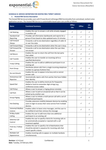
KX-TDA200BXCONTENTSPage1 ABOUT LEAD FREE SOLDER (PbF: Pb free)1.1. SUGGESTED PbF SOLDERPage311.1. INTRUDUCTION31311.2. TYPICAL EXAMPLE3211.3. MPR CARD3311.4. ERROR LOG501.2. HOW TO RECOGNIZE THAT Pb FREE SOLDER ISUSED42 FOR SERVICE TECHNICIANS43 CAUTION12 DIAGNOSIS55512.1. DIAGNOSIS FEATURES553.1. NOTE512.2. DIAGNOSIS TEST593.2. SAFETY PRECAUTIONS53.3. INSULATION RESISTANCE TEST53.4. BATTERY CAUTION514 TERMINAL GUIDE OF ICS, TRANSISTORS AND DIODES683.5. CAUTION515 HOW TO REPLACE A FLAT PACKAGE IC6913 IC DATA13.1.6464615.1. PREPARATION694.1. GENERAL DESCRIPTION615.2. PROCEDURE694.2. CHARACTERISTICS615.3. REMOVING SOLDER FROM BETWEEN PINS694.3. SYSTEM CAPACITY74 SPECIFICATIONS5 SYSTEM OVERVIEW5.1. SYSTEM CONFIGURATIONS5.2. SYSTEM COMPONENTS5.3. SYSTEM CONNECTION DIAGRAM16 CABINET AND ELECTRICAL PARTS LOCATION16.1. EXTENSION BOARDS FOR SERVICING87071817 ACCESSORIES AND PACKING MATERIALS72918 REPLACEMENT PARTS LIST731018.1. CABINET AND ELECTRICAL PARTS736 NAME AND LOCATIONS1218.2. ACCESSORIES AND PACKING MATERIALS737 DISASSEMBLY INSTRUCTIONS1318.3. MPR CARD PARTS747.1. DISASSEMBLY INSTRUCTION (MPR CARD)1318.4. BACK/LED BOARD PARTS797.2. DISASSEMBLY INSTRUCTION (BACK BOARD)1418.5. FIXTURES AND TOOLS808 OUTLINE1619 FOR THE SCHEMATIC DIAGRAM818.1. GENERAL DESCRIPTION1620 SCHEMATIC DIAGRAM828.2. SYSTEM CONTROL1720.1. MPR CARD828.3. BACK BOARD SIGNAL CONNECTION DIAGRAM2020.2. BACK/LED BOARD8720.3. WAVEFORM909 MPR CARD CIRCUIT OPERATION9.1. MPR CARD232321 PRINTED CIRCUIT BOARD9210 BACK BOARD CIRCUIT OPERATION3021.1. MPR CARD9211 TROUBLESHOOTING GUIDE3121.2. BACK/LED BOARD942
KX-TDA200BX1 ABOUT LEAD FREE SOLDER (PbF: Pb free)Note:In the information below, Pb, the symbol for lead in the periodic table of elements, will refer to standard solder or solder thatcontains lead.We will use PbF when discussing the lead free solder used in our manufacturing process which is made from Tin, (Sn), Silver,(Ag), and Copper, (Cu).This model, and others like it, manufactured using lead free solder will have PbF stamped on the PCB. For service and repairwork we suggest using the same type of solder although, with some precautions, standard Pb solder can also be used.Caution· PbF solder has a melting point that is 50 70 F, (30 40 C) higher than Pb solder. Please use a soldering iron withtemperature control and adjust it to 700 20 F, (370 10 C). In case of using high temperature soldering iron, pleasebe careful not to heat too long.· PbF solder will tend to splash if it is heated much higher than its melting point, approximately 1100 F, (600 C).· If you must use Pb solder on a PCB manufactured using PbF solder, remove as much of the original PbF solder as possibleand be sure that any remaining is melted prior to applying the Pb solder.· When applying PbF solder to double layered boards, please check the component side for excess which may flow onto theopposite side (See figure, below).1.1.SUGGESTED PbF SOLDERThere are several types of PbF solder available commercially. While this product is manufactured using Tin, Silver, and Copper,(Sn Ag Cu), you can also use Tin and Copper, (Sn Cu), or Tin, Zinc, and Bismuth, (Sn Zn Bi). Please check the manufacturer’s specific instructions for the melting points of their products and any precautions for using their product with othermaterials.The following lead free (PbF) solder wire sizes are recommended for service of this product: 0.3mm, 0.6mm and 1.0mm.3
KX-TDA200BX1.2.HOW TO RECOGNIZE THAT Pb FREE SOLDER IS USEDMarked PbF (PbF is marked around here)(Component 241L40114 IC311 81R307781R306ICR12R12R12R10R10R161416 IC310 9 IC11144C402J3142322R230111610111RESR550R232RA3098 12SGR211R216PbFR209L204 R229L205FIL20414L206 R231IC1L207FIL205L208 R233R218 L210C212CN211R220IC3029 INX20248RA202 243725 C213 36R244R242R251R240J113Marked PbF (PbF is marked around here)(Component View)A1CN110B1B45A45A1CN111B1B45A45C209 R347C210 R344R348 R343R345 R346C207 C208R313 R306R307 R303R308 R302R314 R305R315 R304PbFA1C204 R311C203 R317C201R318 R342 R316R312 R340 R310C202 R309R301R326C205 R334R329 R323R325 328BCN114B1R333 R338 R335R332 R330C206 R337 R331R336B45CN113B1CN112L104 L106L111 L107 L108 L101L105 L110L112 L109L10219L1032 FOR SERVICE TECHNICIANSICs and LSIs are vulnerable to static electricity.When repairing, the following precautions will help prevent recurring malfunctions.1. Cover the plastic parts boxes with aluminum foil.2. Ground the soldering irons.3. Use a conductive mat on the worktable.4. Do not touch IC or LSI pins with bare fingers.413CN201
KX-TDA200BX3 CAUTION3.1.NOTEWhen you note the serial number, write down all of the 11 digits.The serial number may be found on the label affixed to the bottom of the unit.3.2.SAFETY PRECAUTIONS1. Before servicing, unplug the power cord to prevent an electric shock.2. When replacing parts, use only the manufacturer s recommended components for safety.3. Check the condition of the power cord. Replace if wear or damage is evident.4. After servicing, be sure to restore the lead dress, insulation barriers, insulation papers, shields, etc.5. Before returning the serviced equipment to the customer, be sure to perform the following insulation resistance test to preventthe customer from being exposed to shock hazards.3.3.INSULATION RESISTANCE TEST1. Unplug the power cord and short the two prongs of the plug with a jumper wire.2. Turn on the power switch.3. Measure the resistance value with ohmmeter between the jumpered AC plug and each exposed metal cabinet part, such asscrew threads, control shafts, handle brackets, etc.Note:Some exposed parts may be isolated from the chassis by design. These will read infinity.4. If the measurement is outside the specified limits, there is a possibility of shock hazard. The equipment should be repaired andrechecked before it is returned to the customer.3.4.BATTERY CAUTION1. Danger of explosion if battery is incorrectly replaced. Replace only with the same or equivalent type recommended by themanufacturer. Dispose of used batteries according to the manufacturer’s Instructions.2. The lithium battery is a critical component (type No.CR23541). Please observe for the proper polarity and the exact locationwhen replacing it and soldering the replacement lithium battery in.3.5.CAUTIONThe power socket wall outlet should be located near this equipment and be easily accessible.5
KX-TDA200BX4 SPECIFICATIONS4.1.GENERAL DESCRIPTIONControl BusCommunication BusSwitchingPower InputPSU-M(KX-TDA0104)PSU-L(KX-TDA0103)External BatteryMaximum Power Failure ToleranceMemory Backup DurationDiallingTrunkExtensionMode ConversionRing FrequencyTrunk Loop ence Call TrunkMusic on Hold (MOH)PagingSerial Interface PortInternalExternalRS-232CUSBExtension Connection CableDimensionKX-TDA200Weight (when fully mounted) KX-TDA2004.2.Original bus (16 bit, 8 MHz,10 megabytes per second)H.100 bus conformity (1024 time slot)Non Blocking Distributed Time Switch100 V AC to 130 V AC/200 V AC to 240 V AC, 2.5 A/1.4 A, 50 Hz/60 Hz100 V AC to 130 V AC/200 V AC to 240 V AC,5.1 A/2.55 A, 50 Hz/60 Hz 36 V DC ( 12 V DC x 3, battery capacity of 28 Ah or below recommended for 1 externalbattery)300 ms (without using backup battery)7 yearsDial Pulse (DP) 10 pps, 20 ppsTone (DTMF) DiallingDial Pulse (DP) 10 pps, 20 ppsTone (DTMF) DiallingDP-DTMF, DTMF-DP20 Hz/25 Hz (selectable)1600 Ω maximum0 C to 40 C10%to 90% (non condensing)From 10 x 3-party conference call to 4 x 8-party conference call2 ports (Level Control: -11 dB to 11 dB in 1 dB steps)MOH1: External Music Source portMOH2: Selectable Internal/External Music Source portLevel Control: -6 dB to 3 dB in 3 dB steps2 ports (Volume Control: -15 dB to 15 dB in 1 dB steps)1 (max 115.2 kbps)1SLT1 pair wire (T, R)DPT1-pair wire (D1, D2) or2-pair wire (T, R, D1, D2)APT2-pair wire (T, R, D1, D2)DSS Consoles and Add-on Key Module1-pair wire (D1, D2)430 mm (W) x 415 mm (H) x 270 mm (D)(17 1/5 in x 16 3/5 in x 10 4/5 in)Under 16 kg (35.2 lb)CHARACTERISTICSTerminal Equipment Loop Limit· PT: KX-T76xx series and KX-T7560/KX-T7565: 90 Ω; all other DPTs/APTs: 40 Ω· SLT: 600 Ω including set· Doorphone: 20 ΩMinimum Leakage ResistanceMaximum Number of ExtensionInstruments per LineRing VoltageTrunk Loop LimitHookswitch Flash/Recall Timing RangeBRI Cards Internal ISDN ModeDoor Opener Current LimitPaging Terminal ImpedanceMOH (Music on Hold) Terminal Impedance· CS: 130 Ω15000 Ω maximum1 for PT or SLT2 by Parallel or eXtra Device Port connection of a PT and an SLT75 Vrms at 20 Hz/25 Hz depending on the Ringing Load1600 Ω maximum24 ms to 2032 msSupply Voltage: 40 VPower Supply: 4.5 W per 1 line, 10 W per 4 lines (BRI4)4.5 W per 1 line, 20 W per 8 lines (BRI8)Power Supply Method: Phantom Power Supply24 V DC/30 V AC, 1 A maximum600 Ω10000 Ω6
KX-TDA200BX4.3.SYSTEM CAPACITY4.3.1.Maximum Trunk nd Extension CardsThe following number of trunk and extension cards can be installed in the main unit (Hybrid IP-PBX) for expansion.Card TypeTrunk Card *1Extension CardTotalKX-TDA2008810*1 One T1, E1, PRI30 and PRI23 card counts as 2 cards.Note:· For each card, a maximum number that can be installed in the main unit (Hybrid IP-PBX) is listed in "Installation Manual".· Any card that exceeds the capacity of the main unit (Hybrid IP-PBX) will be ignored.· When the main unit (Hybrid IP-PBX) starts up with an invalid configuration mode, some cards will be ignored.4.3.2.Maximum Terminal EquipmentThe following number of terminal equipment can be supported by the main unit (Hybrid IP-PBX).Terminal Equipment TypeTelephone *1CSPSVoice MailDoorphoneDoor OpenerKX-TDA2001283212821616*1 When only T76xx series and T7560, T7565 DPTs and SLTs are connected. If other DPTs or APTs are connected, themaximum number will decrease as each of these units is counted as 4 sets of SLTs or DPTs (T76xx series and T7560, T7565).4.3.3.Power Supply Unit SelectionMain unit (Hybrid IP-PBX) needs an optional power supply unit (PSU) suitable for its configuration. Calculate the amount of"load figures" from the type and number of equipment to be connected, and determine the type of PSU that will be required.Load Figure CalculationPTExtension Card *1Equipment TypeDPT (T76xx series and T7560, T7565)Other DPT/APT/DSS ConsoleDHLC8SLC8SLC16MSLC16CSISDN ExtensionVoice Mail*1 Only the extension cards that can support SLTs count for the load figures.PSU CapabilityEach PSU supports a different amount of load figures.PSU TypeMaximum Load Figures128512PSU-M *2PSU-L*2 Available for the KX-TDA100 and KX-TDA200.7Load Figure14881616421
KX-TDA200BX5 SYSTEM OVERVIEW5.1.SYSTEM CONFIGURATIONS8
KX-TDA200BX5.2.SYSTEM COMPONENTSModelShelfKX-TDA200BXMain Central ProcessingCardMPR Option CardKX-TDA0196XJCO Line X-TDA0290XKX-TDA0480XExtension 2XJKX-TDA0173XJKX-TDA0174XJKX-TDA0175XJOther 1XJKX-TDA0410XJPower Supply UnitsKX-TDA0103XJ(PSUs)KX-TDA0104XJCell Stations (CS’s)KX-TDA0142CEProprietary Equipment KX-A228XJKX-A229XJKX-A258XJKX-T30865XCard PB3MSG4CTI-LINKPSU-LPSU-MDescriptionBasic ShelfMain Processing CardRemote Card8-Port Analogue Trunk Card16-Port Analogue Trunk Card8-Port E &M Trunk CardE-1 Trunk Card8-Port Caller ID Card4-Port BRI Card8-Port BRI CardPRI CardPRI Card4-Channel VoIP Gateway Card8 Cell Station Interface Card8-Port Digital Hybrid Extension Card8-Port Digital Extension Card16-Port Digital Extension Card8-Port Single Line Telephone Extension Card16-Port Single Line Telephone Extension Card16-Port Single Line Telephone Extension with Message Lamp Card4-Port Doorphone Card16-Channel Echo Canceller CardOptional 3-Slot Base Card4-Channel Message CardCTI Link CardL-Type Power Supply UnitM-Type Power Supply Unit4-Channel Cell Station Unit for DECT Portable StationS/M-type Back-up Battery CableL-type Back-up Battery CableBlank Slot CoverDoorphoneAvailable TelephonesThis main unit (Hybrid IP-PBX) supports all of the Panasonic X-T7xxx and KX-TD7xxx series:· Digital/Analog proprietary telephones (e.g., KX-T7625, KX-T7630, KX-T7633, KX-T7636)· Portable stations (e.g., KX-TD7690, KX-TD7680)· DSS consoles (e.g., KX-T7640)This main unit (Hybrid IP-PBX) does not support the following telephones:· KX-T308xx series Proprietary Telephones and DSS consoles· KX-T616xx series Proprietary Telephones and DSS consoles· KX-T1232xx series Proprietary Telephones and DSS consolesFor the equipment (e.g., Add-on Key Module, USB Module, Headset) that can be connected to a particular telephone, refer tothe telephone s manual.Abbreviations in this manualProprietary telephone: PTDigital proprietary telephone: DPTAnalog proprietary telephone: APTPortable station: PSSingle line telephone: SLTNote:· There are some optional service cards and features that are not available for certain countries/areas.Consult yourauthorized Panasonic dealer for detailed instructions.· The power supply capacity of this main unit (Hybrid IP-PBX) may differ from the values described in this manual dependingon the model number. Please consult your dealer for detailed information.9
KX-TDA200BX5.3.SYSTEM CONNECTION DIAGRAM10
KX-TDA200BX*Only 1 Server PC can be connected to the main unit (Hybrid IP-PBX). Two or more Server PCs cannot be used simultaneously.11
KX-TDA200BX6 NAME AND LOCATIONSRUN IndicatorALARM IndicatorLED TypeLED1(Power/RUN)LED2(Alarm)Slot TypeFree Slots 1 to 10Option Card SlotMPR Card SlotColorGreenRedUsage and Status DefinitionDisplay of Power Supply & RUN StatusOFF: Power OFF (inc. in normal resetting)ON: Power ON & RUN (On-Line)Flash (60/min.): Power ON & In startingFlash (120/min.): Power ON & In resetting before system clearDisplay of ALARMOFF: NormalON: Alarm (CPU stop, Alarm for each card)Flash: Alarm (MPR file error in restarting)MPR CardCO Line CardsExtension CardsYesNoNoNoNoYes12OPB3 CardCTL-LINK CardYesYesNo
KX-TDA200BX7 DISASSEMBLY INSTRUCTIONS7.1.DISASSEMBLY INSTRUCTION (MPR CARD)1. Remove the Lib by sliding it in the direction of arrow 1.2. This will be removed if the user attached a Pad Lock as shown in aFig.1.3. Loosen the Screw.4. Front Cover is removed in the direction of arrow 2.5. Loosen the two Screws.6. Remove the MPR Card.13
KX-TDA200BX7.2.DISASSEMBLY INSTRUCTION (BACK BOARD)1. Remove four Screws (A).2. Remove the Left Side Cover and the Right Side Cover.3. Remove the Hook. Remove the Top Cover.4. Remove nine Screws (B).5. Remove the Back Cover.14
KX-TDA200BX6. Remove the RS-232C Connector and LED Connector from BackBoard 1.7. Remove eight Screws (C).8. Remove Back Board 1.9. Remove the LED Connector from Back Board 2.10. Remove the Screw (C).11. Remove Back Board 2.15
KX-TDA200BX8 OUTLINE8.1.GENERAL DESCRIPTIONThe control system of the main unit is composed of the main central processing card (MPR card) controlling the entire systemand exchanging voice data, the circuit control section (LPR/LC) controlling various telephone lines and the power supply section(POWER).MPR card, LPR/LC and POWER are connected each other through the System BUS (ADDRESS BUS, DATA BUS andCONTROL BUS). MPR card and LPR/LC are under I/O control (I/O Read/Write) by MPR card.MPR card controls LPR which have a microprocessor by the lnter-Microprocessor Communication System supported by ASIC.Those are, MPR card and LPR exchange controlling messages through bi-directional buffer and CPU controls LPR so that itcan manage multiple telephone lines. Since LC does not have a microprocessor, it is completely controlled through ASIC fromMPR card.I/O address for LPR access is fixed for each free slot. CPU discriminates the sort of LPR through the inter-processorcommunication system.POWER detects the voltage drop of the AC input and the DC output and transfers it to MPR card.8.1.1.MPR CardThis card is the main control section of main unit. It controls all the cards mounted on the free slots, and communication of RS232C ports.There are two LED (BATT ALARM, SD ACCESS), one SD card slot, one push switch, one slide switch, one USB port, two MOHjacks, and two EPG jacks in the front of MPR card. BATT ALARM LED light red if the output of the lithium battery in MPR cardis set to about 2.8V or less. During access to SD card, it green-blinks or SD ACCESS LED light and blink. Enclosed SD cardis used for SD card slot on a main part, putting in. The main program is stored in SD card. It connects with PC and a USB portis used for a maintenance or a system setup. The external sound source for BGM or suspension sound is connected to a MOHjack. A speaker with amplifier is connected to external paging at an EPG jack. Light Emitting Diode (RUN indicator,ALARMindicator) arranged at the main part upper part is directly controlled from MPR card, and shows the state of a systemof operation.This control circuit executes the control signals for the exchange process, and this card is composed of the following(A) 32bit CPU (32bit data bus)(B) SDRAMs, SRAMs(C) Flash memorys(D) Lithium Battery for back-up of clock IC and Static RAMs8.1.2.Back BoardBB (back board) is the mother board of the basic shelf. This board connects each card/unit (POWER, MPR card, and optionalservice cards) together. This board has one RS-232C connector.8.1.3.Power Supply UnitThis unit is switching regulator power supply and supplies DC voltages to MPR card, and optional service card (free slot). PSU(power supply unit) has four outputs (40V, 30V, 15VPT, 15V). 15V output is supplied only in MPR card and option card. Otheroutputs are mainly used as an object for the electric supply to a terminal. Refer to each S/M for the details of PSU.16
KX-TDA200BX8.2.8.2.1.SYSTEM CONTROLSystem Control Block Diagram17
KX-TDA200BX8.2.2.Voice (TDM Highway) Bus Block Diagram18
KX-TDA200BX8.2.3.Voice Bus Logical AssignmentIn the line card, the CT D line number, which is output in accordance with the inserted slot, and the time slot are assigned bysoftware.For the detail of output slot for each card (optional service card), refer to the service manual of the card (optional service card).8.2.4.Back Board SignalingBack board waveform of TDM bus for voice19
KX-TDA200BX8.3.8.3.1.BACK BOARD SIGNAL CONNECTION DIAGRAMCT Bus System Connection Diagram20
KX-TDA200BX8.3.2.EC Bus System Connection Diagram21
KX-TDA200BX8.3.3.System Control and Analog Signal Connection Diagram8.3.4.Power Supply System Connection Diagram22
KX-TDA200BX9 MPR CARD CIRCUIT OPERATION9.1.MPR CARD9.1.1.Outline1) Function· System Control· Circuit Switching (includes gain adjustment function)· Conference Call (3 people x 8 8 people x 3)· MOH· PAGING· Clock2) Configuration· Power Supply: DC/DC Converter· CPU: HITACHI SH7709S (133MHz)· ASIC: Our own products· ROM: 4Mbit x 1 (for boot programs)· SDRAM: 64Mbit x 2 (for work area)· SRAM: 4Mbit x 2 (for user data backup)· SD card I/F (for operating programs) x 1· USB I/F (for PC programming) x 1· MOH: External sound input x 2· PAGING: External output x 2· Expanded memory connector x 1· Modem card connector x 13) Operation Rating· Power Input : 15V· Power Output : 15V (for MOH) 3.3V (for I/O) 3.3VBB (back board signal line pull-up) 3.3VB (for SRAM backup) 1.8V (for CPU core) 1.9VB (for clocking backup) 9.4V (for RS-232C driver/receiver) 5VRMT unused (for remote card) 5V (for RS-232C driver/receiver)23
KX-TDA200BX9.1.2.Description of Each PartLED (BATALM): Lights when the lithium battery voltage drops below 2.8V.LED (SD ACCES): Lights on when the SD card is being accessed.SD card slot: Mounts the system program SD card.Reset Switch: Press to reset the system.System Initialize Switch:On default startup, set the switch to the "SYSTEM INITIALIZE" position before turning the power ON. Return the switch to the"NORMAL" position when the main power switch starts to flash. On normal startup, turn the power ON with this switch in the"NORMAL" position.USB connector: B-type connector. Used for PC programming.MOH 1, 2: External music on hold input.PAGING 1, 2: External PAGING output. Connect to a device with a built-in amplifier.24
ADD BUSCNT BUSDATA BUSDbusBufferLD[15:0]OSC12MHz X201X202to CPUnDREQ0,1nDACK0,1 3.3V 1.8VnRDDQMLU,DQMLLADD0-7nCS SDBP-I/O PortsPCMCIA InterfaceJTAG InterfaceSIO(SCI0)SIO with FIFO(SCI2)X101OSC16.384MHzDSRs,DTRs, RTS, CTS,nINIT, DIPSWsAC ALM,DC ALM,nBATALMPOWTYPE[1:0],nBATT(16bit bus)4Mbit*2SRAMTotal:1MB(16bit bus)4Mbit 3.3V 3.3VCH SEL2nIRQIC409 15V/GNDIC406AGCIC408nCS 5nWRnRDnBSCODEC( 3.3V)IC405Mu/nA-9VIC121IC12090pin DINRXD1, CS1, DR1LEDRUNLEDALMRING SYNCRING LOSTXD1, RS1, ER1RCV 5VCT NETREFCT D[7:0]CT FRAMECT C8EC CLKEC nRSTEC AD[15:0]EC CBE[1:0]EC nPAREC nFRAMEEC nTRDYEC nSTOPEC nPERREC nCDETEC nINT(EC IDSEL) 3.3V BB(for B.B.) 15VGNDDRV 9V,-9VH100 bus 3.3VTerminationEC busLimitter 3.3V CurrentIC403 1.8VSeries Reg.SW Reg.IC402 3.3VKX-TDA200 MPR CARD BLOCK DIAGRAMfrom CPU(Output Port)from ASIC(Output Port)from ASICto CPU(Input Port) 5VSeries Reg. 9VEC CLKEC nRSTEC AD[15:0]EC CBE[1:0]EC nPAREC nFRAMEEC nTRDYEC nSTOPEC nPERREC nCDETEC nINTIC102ASICSW Reg.IC413 15VSDI,SDO,CTS,RTSCT NETREFLDHW0,LUHW0CT D[7:0]nF0,HW CLKCT FRAMECT C8CH SEL[2:0]PIO[7:4]nIRQnBREQnBACKnCSnWRnRDnBSD0-D15 DATAA1-A23 ADDHALT, Mu/nA,MOH SEL,MELODY SELX103TCXO16.384MHzTxD,RxD,CTS,RTS(UART i/f)CODEC( 3.3V)AGC64Mbit*2(32bit bus)SDRAMTotal:16 MBIC305, IC306nBREQnBACKUHW,DHW,CLK(4.096MHz)DTR,DSR 3.3VnPRS RMTGAIN0,GAIN1Battery( 3.0V)IC404Regulator( 1.8V)IC303FLASHTotal:512KBMELODY SEL(Software)MelodyIC410 ICMOH-SEL(Software)RMT card(Option)VRTC 3.3VBLD[15:0]ADD1-19nCS 4RD/nWRnRD 3.3VB7pin Conn.(Debug Interface)DTR,RTS,LEDs,REG,BELTIME(Checker Pad only)(for RS232C port)IC107LocalResetSIO with FIFO(SCI1)DQMUU,DQMULCoreCLK 01 3.3VBDC ALM,nIRQ USB, nIRQ SDBIC103RTCInterrupuControllerCS GenerationforFlash,SRAM,SDB, USBD[31:0]LD[15:0]ADD[25:0]nCS 2 etc.RD/nWRnRASnCASCKIOCKECPUDMACBus ArbiternWR, nRDnCS0,3,4nRASs, nCASs,etcIC123, IC124MPR CardSW103InitializeSWSW101(Manual Reset SW)Resetto Reset ICLED103BATT ALARMSD-ACCESSLED101CN209OSC20MHzD[31:0]USB LU,DQMLLIC301, IC302LD[15:0]MEC Card(Expansion Memory)(Future option)DQMUU,DQMULSD Card Interface(MN5773)IC205CH SEL1MOH2CH SEL0ADD1-23RD/nWRnRDnCS 0Paging230pin ConnectionD[31:0]ADD2-15nCS .SD CardKX-TDA200BXBlock Diagram
KX-TDA200BX9.1.4.Circuit Description9.1.4.1.Outline of Block Description· CPU blockOperates the main unit control. Also operates various controls, generation of select signal, DMA control and serial port control.This contains the built-in clock function.· ASIC blockProvides the communication between each optional service card, call control (TSW function), conference call, tone generationand gain control function.· Memory blockThis is a work area used for the main unit control program storage, the system boot program storage, or the user configurationdata storage.· USB blockProvides the USB I/F function. Connects to the PC to be used for PC programming or system data load/store.· SD card blockProvides the SD card I/F function and loads the main unit program and the system data from the SD card containing the mainunit control program.· MOH/PAGING blockProvides the external music on hold input x 2, and the external paging output x 2 port. Also this provides the external music onhold input 1 system and exclusively the internal music on hold output.· Power blockConsists of DC/DC converter circuit and various regulators.9.1.4.2.Detail of Block Description· CPU blockConfiguration: IC101 (CPU), IC107 (reset IC), IC103 (spread clock IC), X101 (CPU source clock), X102 (clocking clock) etc.Function: (IC101)Generates the select signal in accordance with the memory map and operates read/write of data between each peripheral.Controls the DMA transfer between USB I/F or built-in serial controller and memory.Operates input/output control of each I/O signal in accordance with the program.Contains the built-in clock function (battery backup) with the source clock X102 (32.768 kHz).(IC107)Monitoring the power voltage, it generates a reset signal when the voltage drops under the constant value (2.9Vtyp) or whenthe reset switch is pressed down.(IC103)To reduce unnecessary radiation, it generates the clock with the constant blurring mainly X101 clock output (16.384 MHz).Description of the Signal on MPRSignal Name 15VIN 15V 9.4V 5V 5VRMT3.3V BB 3.3VB 3.3V1.9VB1.8VA[0]-A[25]nAC ALMnBACKnBATTFunctions 15V DCFor Circuit 15V DC MOHFor Driver IC 9.4V DC RS-232CFor Driver IC 5V DC RS-232CReserve 3.3V DCFor pull-up of back board signal line 3.3V DCBattery backupFor SRAM (IC301, IC302) backup 3.3V DC 1.9V DCBattery backupFor clock function of CPU (IC100)For Core 1.8V DC CPU (IC100)Address busAC alarm signal: Indicates AC voltage cutoff. (L: Alarm condition)Bus Acknowledge: Indicates Bus Acknowledge.Indicates whether external battery is connected or not. L: Connected26
KX-TDA200BXSignal NamenBAT ALMnBREQnBSnCASLnCASUCH SEL[0]CH SEL[1]CH SEL[2]CKECKIOnCS0nCS2nCS3nCS4nCS5nCS6nCS FLASH0nCS FLASH1nCS SDB0nCS SDB1nCS SRAM0nCS SRAM1nCS USBnCTS2CTS RMTCT C8CT D[0] -[7]CT FRAMECT NETREFC CS[0]D[0] -D[31]nDACK0-1DCD2DCLK RMTnDC ALMDIN RMTDOUT RMTDQMLL (nWE0)DQMLU (nWE1)DQMUL (nWE2)DQMUU (nWE3)nDREQ0-1DSR2DSR RMTDTR2EC AD[0] -[15]EC nCBE[1]-[0]EC nCDETEC CLKEC nFRAMEEC nINTEC PAREC nPERREC nRSTEC nSTOPEC nTRDYnFAN ALMFSEL0GAIN0-1HALTnINITnIRQ ASICnIRQ SDBnIRQ USBFunctionsBattery Alarm Signal: Indicates the declined voltage of lithium battery. (L: Alarm condition)Bus Request: Bus request signalBus Cycle Start: Bus cycle start signalLower Byte Address Column Address Strobe: CAS signal for SDRAMUpper Byte Address Column Address Strobe: CAS signal for SDRAMSynchronous Signal for CODEC (For MOH#1/Page#1)Synchronous Signal for CODEC (For MOH#2/Page#2)Synchronous Signal for CODEC (For RMT)Clock Enable: CKE signal for SDRAMClock I/O Terminal: For bus clock of SDRAM (IC305, IC306) and ASIC (IC101) CPU (IC100) outputs the clock of fourtimes frequency as Source clock (16.384MHz).Chip Select 0: Chip select signal for flash memoryChip Select 2: Chip select signal for the expanded SDRAM (Future Option, Reserve at present.)Chip Select 3: Chip select signal for SDRAMChip Select 4: Chip select signal for SRAMChip Select 5: Chip select signal for ASICChip Select 6: Chip select signal for USB I/F and SD card I/FChip Select for Flash memory 0: CS signal for IC303Chip Select for Flash memory 1: CS signal for IC304 (reserve)Chip Select for Sd card I/FReserveChip Select for SRAM 0: CS signal for IC301Chip Select for SRAM 1: CS signal for IC302Chip Select for USB I/FClear To Send from RS-232C connectorClear to Send: Flow signal for modemClock 8.192MHz clock outputted from PLL masterCT Data Bus: Two-way serial data bus to which the drive from any card is possible in the system.Frame Signal: 8KHz frame signal outputted from the masterBackup Synchronous Signal (MAX 2MHz) 8KHz signal output from slave etc.Chip Select For RMTData BusDMA Acknowledge: For USB I/FData Carrier DetectCodec Clock (8MHz): For RMTDC ALARM:DC alarm signal; Indicates the declined DC voltage. (L: Alarm condition)Codec Data Input: For RMTCodec Data Output: For RMTData Input/Output Mask (Write Enable): DQM signal for SDRAM and WE signal for each memory IC and ASICDMA Request: For USB I/FData Set Ready from RS-232C connectorData Set Ready from RS-232C connectorData Terminal Ready to RS-232C connectorAddress of EC Synchronous Bus, Data Bus (4MHz)EC Bus Command/Byte Enable: The initiator drives as bus command in the address phase and as byte enable in thedata phase.EC Line Card Detection Signal Asynchronous interrupting signalClock of EC Synchronous Bus (8MHz) All EC bus signals except nRESET/EC INT operates in sync with this signal.EC Cycle Frame Signal: Indicates the drive by initiator and the execution of ECI bus cycle.EC Interrupting Signal: Be asserted when slave interrupt occurs.Parity Bit of EC Synchronous Bus: Drive by applying even parity to AD[15:0] and CBE[1:0]. (4MHz)EC Parity Error: Flag indicating error status by parity flagEC Reset Input: System reset input signalEC Bus Stop Signal: Be asserted when target requests transaction halt to initiator.EC Target Ready Signal: Indicates the drive by target and the possible data transfer.Fan Alarm: It goes Low at the error of the L Power Supply’s FAN. It goes High when the FAN is normal and, PowerSupply S and M, which does not carry the FAN, are used.Signal which switches the Flash Memory address of the MEX card. FSEL0 is set by hard jumper. L: The number ofFlash Memory chips on the MPR is 1pc. H: The number is 2pcs.Gain: Gain adjustment signal for the RMT card (Reserve)Alerts the occurrence of the declined DC voltage to line card. H: Activ
Hybrid IP-PBX IMPORTANT INFORMATION ABOUT LEAD FREE, (PbF), SOLDERING If lead free solder was used in the manufacture of this product the printed circuit boards will be marked PbF. Standard leaded, (Pb), solder can be used as usual on boards without the PbF mark.