Transcription
LECTURE NOTESONPOWER SYSTEM - I
Theory of Thermal Power StationThe theory of thermal power station or working of thermal power station is very simple. A powergeneration plant mainly consists of alternator runs with help of steam turbine. The steam is obtainedfrom high pressure boilers. Generally in India, bituminous coal, brown coal and peat are used as fuelof boiler. The bituminous coal is used as boiler fuel has volatile matter from 8 to 33 % and ashcontent 5 to 16 %. To increase the thermal efficiency, the coal is used in the boiler in powder form.In coal thermal power plant, the steam is produced in high pressure in the steam boiler due toburning of fuel (pulverized coal) in boiler furnaces. This steam is further supper heated in a superheater. This supper heated steam then enters into the turbine and rotates the turbine blades. Theturbine is mechanically so coupled with alternator that its rotor will rotate with the rotation of turbineblades. After entering in turbine the steam pressure suddenly falls and corresponding volume of thes t eam i ncr ea s es . Af t er im part i ng ener gyt ot he. t urbi necomr ot or t he st eam pas s es out of t he t ur bi ne bl ades i ntoJnt uM at eri al st hecondens er. I nt hecondense r t hecol d wat er is ci r cul at ed wit ht he hel p of pum pwhi chcondenses the low pressure wet steam. This condensed water is further supplied to low pressurewater heater where the low pressure steam increases the temperature of this feed water, it is againheated in high pressure.For better understanding we furnish every step of function of a thermal power station as follows,1) First the pulverized coal is burnt into the furnace of steam boiler.2) High pressure steam is produced in the boiler.3) This steam is then passed through the super heater, where it further heated up.4) This supper heated steam is then entered into a turbine at high speed.5)In turbine this steam force rotates the turbine blades that means here in the turbine thestored potential energy of the high pressured steam is converted into mechanical energy.
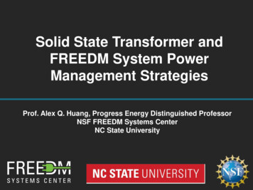
Line Diagram of Power Plant:.com6) After rotating the turbine blades, the steam has lost its high pressure, passes out of turbineblades and enters into a condenser.7) In the condenser the cold water is circulated with help of pump which condenses the lowpressure wet steam.8) This condensed water is then further supplied to low pressure water heater where the lowpressure steam increases the temperature of this feed water, it is then again heated in a high pressureheater where the high pressure of steam is used for heating.9) The turbine in thermal power station acts as a prime mover of the alternator.
Overview of Thermal Power Plant:A typicalThermal PowerStationOperatesonaCyclewhichisshownbelow.In steam boiler the water is heated up by burning the fuel in air in the furnace & the function of theboiler is to give dry super heated steam at required temperature.JntumaterialsThe working fluid is water and steam. This is called feed water and steam cycle. The ideal.Thermodynamic Cycle to which the operation of a Thermal Power Station closely resembles is theRANKINE CYCLE.The steam so produced is used in driving the steam Turbines. This turbine is coupled to synchronousgenerator (usually three phase synchronous alternator), which generates electrical energy.The exhaust steam from the turbine is allowed to condense into water in steam condenser of turbine,which creates suction at very low pressure and allows the expansion of the steam in the turbine to avery low pressure. The principle advantages of condensing operation are the increased amount ofenergy extracted per kg of steam and thereby increasing efficiency and the condensate which is fedinto the boiler again reduces the amount of fresh feed water.The condensate along with some fresh make up feed water is again fed into the boiler by pump(called the boiler feed pump).com
In condenser the steam is condensed by cooling water. Cooling water recycles through cooling tower.This constitutes cooling water circuit.The ambient air is allowed to enter in the boiler after dust filtration. Also the flue gas comes out ofthe boiler and exhausted into atmosphere through stacks. These constitute air and flue gas circuit. Theflow of air and also the static pressure inside the steam boiler (called draught) is maintained by twofans called Forced Draught (FD) fan and Induced Draught(ID) fan.The total scheme of a typical thermal power station along with different circuits is illustrated below.
Inside the boiler there are various heat exchangers, viz.’ Economiser’, ‘Evaporator’ (not shown inthe fig above, it is basically the water tubes, i.e. downcomer riser circuit), ‘Super Heater’(sometimes ‘Reheater’, ‘air preheater’ are also present).In Economizer the feed water is heated to considerable amount by the remaining heat of flue gas.The Boiler Drum actually maintains a head for natural circulation of two phase mixture (steam water) through the water tubes.There is also Super Heater which also takes heat from flue gas and raises the temperature of steam asper requirement.Efficiency of Thermal Power Station or PlantThe overall efficiency of a thermal power station or plant varies from 20% to upon plant capacity.Thermal Power Plant Location:26% and it depends
optimizing the profit, the location of the station is much important factor. Power generation plantlocation plays an optimizing part in the economy of the station.A thermal power station or thermal power plant has ultimate target to make business profit. Hence forLet’s Q1(x1, y1), Q2(x2, y2), Q3(x3, y3), Q4(x4, y4), .and Qn(xn, yn)The most economical , location of power plant can be determined by graphical method as describedbelow,The most economical and ideal power plant location is the center of gravity of the load because forsuch a power generation plant the length of the power transmission network will be minimum, thusthecapitalcosttothesystemisreduced.Let’s explain the graphical method, say, X and Y be two reference axes.are n numbers of load centers. From the above graph we get, the coordinates of the center of gravityof the load, Q(x, y) where
Obviously the location of thermal power station is best at the center of gravity of the load, but manytimes it is not possible to establish a thermal power plant at the CG of the load. Since normally CGpoint of the load may be at the heart of the city. so other many points to be considered to decide thebest optimized location of the power plant.1) The electric power generation plant must be constructed at such a place where the cost of landis quite reasonable.2) The land should be such that the acquisition of private property must be minimum.3) A large quantity of cooling water is required for the condensers etc of thermal power generationplant, hence the plant should preferably situated beside big source of natural water source such asbig river.com4) Availability of huge amount of fuel at reasonable cost is one of the major criterion for choosingplant location.5) The plant should be established on plane land.6)The soil should be such that it should provide good and firm foundation of plant and buildings.7) The thermal power plant location should not be very nearer to dense locality as there are smoke,noise steam, water vapors etc.8) There must be ample scope of development of future demand.9) Place for ash handling plant for thermal power station should also be available very near by.10) Very tall chimney of power station should not obstruct the traffics of air ships.Advantages & Disadvantages of Thermal Power StationAdvantages:
1) Economical for low initial cost other than any generating plant.2) Land required less than hydro power plant.3) Since coal is main fuel & its cost is quite cheap than petrol/diesel so generation costis economical.4) There are easier maintenance.5) Thermal power plant can be installed in any location where transportation & bulk of waterare available.1) The running cost for a thermal power station is comparatively high due to fuel, maintenance etc.2) Large amount of smoke causes air pollution. The thermal power station is responsible forGlobal warming.3) The heated water that comes from thermal power plant has an adverse effect on the lives inthe water and disturbs the ecology.4)Over al l ef f i ci ency oft her m al power pl ant i s l owl i ke l ess 30%.Dis advantages :
Overview of Nuclear Reactors:Learning Objectives:Gain broad understanding of PWRs, BWRs, HTGRs
.com
Objectives to Make Electricity1.Make heat2.Remove heat using a fluid or gas3.Pass the fluid or gas through a turbine4.Turning an electric generator to make ElectricityRemoving Heat Fluid (water or liquid metal) or gas is pumped through the core to remove heat generated in fueldue to fissioning. Pumps needed to circulate coolant Transfer directly to turbines or to steam generators (PWRs). Condense steam to recirculate back to the core to provide cooling
Basics of Power Conversion
Power Reactor Types: – Pressurized Water Reactor– Boiling Water Reactor– Natural Uranium Heavy Water Cooled Reactor (CANDU)– RBMK - Russian Chernobyl Like - Water Cooled– Fast Reactors - Liquid Metal (Sodium)– Gas Reactors (CO2 or Helium Cooled)– Molten Salt Cooled Reactors (Organic Coolants)Making Heat Use the fissioning of uranium atoms (or plutonium) to release 200Million electron volts per fission. Need to enrich natural uranium to 3 to 4 weight percent U-235 (from0.7% found in nature. Need to fabricate.fuel
uranium into pellets clad in zironiumassemblies which are placed into the reactor core.Fission EventFF1nU-235nJntuMaterialsFF2n Release of excess neutrons creates the potential for chainreaction. The energy (mostly as kinetic energy of the fission fragments)is substantial.
Energy Release: 1 fission 200 Mev 1 gram U-235 fissioned 8.6x10¹⁰ joules 24,000 kwh(Equivalent to lighting a small city for overnight)24,000 kwh requires 3.2 tons of coal 12.6 bbls oil Energy Density(energy / mass) Energy Density of U-235 28,000 times energy density of coalCreating the Reactor Core:.Important Factors in Design Reactor Core Design Fuel DesignReactor Physics - Core Power DistributionReactivity Control - Ability to shutdown plant Safety Analysis - no fuel failure or melting Core Heat Removal Coolant - Heat Transfer Safety Systems (Emergency)
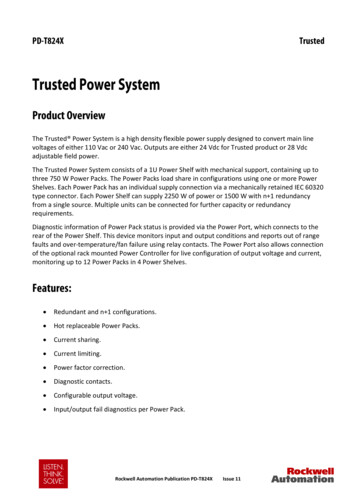
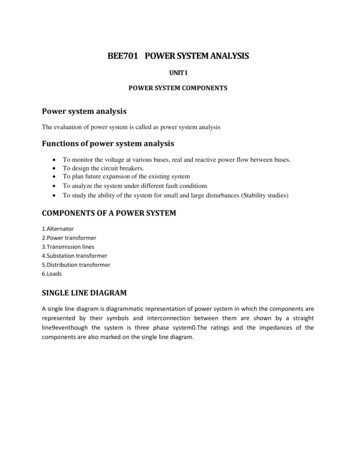
Confinement of Radioactivity Electricity Production BWR Power Cycle.comSchematic Arrangement JntuMaterials of a BWR
Pressurized Water Reactors.Power Cycle –Brayton
How Gas Turbine Power Plants Work::.The combustion (gas) turbines being installed in many of today's natural-gasfueled power plants are complex machines, but they basically involve threemain sections:Jnt uM at eri al sThe compressor:, which draws air into the engine, pressurizes it, and feeds itto the combustion chamber at speeds of hundreds of miles per hour.The combustion system: typically made up of a ring of fuel injectors thatinject a steady stream of fuel into combustion chambers where it mixes withthe air. The mixture is burned at temperatures of more than 2000 degrees F.The combustion produces a high temperature, high pressure gas stream thatenters and expands through the turbine section.The turbine: is an intricate array of alternate stationary and rotating aerofoilsection blades. As hot combustion gas expands through the turbine, it spinsthe rotating blades. The rotating blades perform a dual function: they drivethe compressor to draw more pressurized air into the combustion section, andthey spin a generator to produce electricity.Land based gas turbines are of two types:(1) heavy frame engines and (2)aeroderivative engines. Heavy frame engines are characterized by lowerpressure ratios (typically below 20) and tend to be physically large. Pressureratio is the ratio of the compressor discharge pressure and the inlet airpressure. Aeroderivative engines are derived from jet engines, as the nameimplies, and operate at very high compression ratios (typically in excess of30). Aeroderivative engines tend to be very compact and are useful wheresmaller power outputs are needed. As large frame turbines have higher
power outputs, they can produce larger amounts of emissions, and must bedesigned to achieve low emissions of pollutants, such as NOx.One key to a turbine's fuel-to-power efficiency is the temperature at which itoperates. Higher temperatures generally mean higher efficiencies, which in turn,can lead to more economical operation. Gas flowing through a typical powerplant turbine can be as hot as 2300 degrees F, but some of the critical metals inthe turbine can withstand temperatures only as hot as 1500 to 1700 degrees F.Therefore, air from the compressor might be used for cooling key turbinecomponents, reducing ultimate thermal efficiency.
Introduction:Distribution Systems–GeneralThe electrical energy produced at the generating station is conveyed to theconsumers through a network of transmission and distribution systems. It isoften difficult to draw line between the transmission and distribution systemsof a large power system. It is impossible to distinguish the two merely bytheir voltage because what was considered as a high voltage a few years agois now considered as a low volt-age. In general, distribution system is thatpart of power system which distributes power to the consumers forutilization. The transmission and distribution systems are similar to man’scirculatory system. The trans-mission system may be compared with arteriesin the human body and distribution system with capillaries. They serve thesame purpose of supplying the ultimate consumer in the city with the lifegiving blood of civilization–electricity. In this chapter, we shall confine ourattention to the general introduction to distribution system.
12.1.Distribution System:That part of power system which distributes electric power for local useis known as distribution system.In general, the distribution system is the electrical system between thesub-station fed by the transmission system and the consumers meters. Itgenerally consists of feeders, distributors and the service mains. Fig. 12.1shows the single line diagram of a typical low tension distribution system.(i)Feeders: A feeder is a conductor which connects the sub-station (orlocalised generating station) to the area where power is to be distributed.Generally, no tappings are taken from the feeder so that current in it remainsthe same throughout. The main consideration in the design of a feeder is the.current carrying capacity.(ii)Distributor: A distributor is a conductor from which tappings aretaken for supply to the consumers. In Fig. 12.1, A B, BC, CD and DA are thedistributors. The current through a distributor is not constant becausetappings are taken at various places along its length. While designing adistributor, voltage drop along its length is the main consideration since thestatutory limit of voltage variations is 6% of rated value at the consumers’terminals.(iii)Service mains. A service mains is generally a small cable whichconnects the distributor to the consumers’ terminals.
of Distribution SystemsA distribution system may be classified according to ;i)Nature of current. According to nature of current, distribution system maybe classified as (a) d.c. distribution system (b) a.c. distribution system. Nowa-days, a.c. system is universally adopted for distribution of electric power asit is simpler and more economical than direct current method.(ii)Type of construction. According to type of construction, distributionsystem may be classified as (a) overhead system (b) underground system.The overhead system is generally employed for distribution as it is 5 to 10times cheaper than the equivalent underground system. In general, theunderground system is used at places where overhead construction isimpracticable or prohibited by the local laws.(iii) Scheme of connection: According to scheme of connection, thedistribution system may be classified as (a) radial system (b) ring mainsystem (c) inter-connected system.Each scheme has its own advantages and disadvantages and those arediscussed in Art.12.7.12.3 A.C. Distribution:Now-a-days electrical energy is generated, transmitted and distributedin the form of alternating current. One important reason for the widespreaduse of alternating current in preference to direct current is the fact thatalternating voltage can be conveniently changed in magnitude by means of a.comtransformer. Transformer has made it possible to transmit a.c. power at highvoltage and utilize it at a safe potential. High transmission and distributionvoltages have greatly reduced the current in the conductors and the resultingaccording to voltage or bulk capacity. However, in general, the a.c. distributionsystem is the electrical system between the step-down substation fed by thetransmission system and the consumers’ meters. The a.c. distribution system isclassified into (i) primary distribution system and(ii) secondary distribution system.line losses.
There is no definite line between transmission and distribution(i) Primary distribution system. It is that part of a.c. distribution systemwhich operates at voltages somewhat higher than general utilisation andhandles large blocks of electrical energy than the average low-voltageconsumer uses. The voltage used for primary distribu
Principles of Power System:To depends upon the amount of power to be conveyed and thecomdistance of the substation required to be fed. The most commonly usedprimary distribution voltages are 11 kV, 6·6kV and 3·3 kV. Due to economicconsiderations, primary distribution is carried out by 3-phase, 3-wire system.Fig. 12.2 shows a typical primary distribution system. Electric powerfrom the generating station is transmitted at high voltage to the substationlocated in or near the city. At this substation, voltage is stepped down to 11kV with the help of step-down transformer. Power is supplied to varioussubstations for distribution or to big consumers at this voltage. This formsthe high voltage distribution or primary distribution.(ii)Secondary distribution system: It is that part of a.c. distribution systemwhich includes the range of voltages at which the ultimate consumer utilisesthe electrical energy delivered to him. The secondary distribution employs400/230 V, 3-phase, 4-wire system.Fig. 12.3 shows a typical secondary distribution system. The primarydistribution circuit delivers power to various substations, called distributionsub-stations. The substations aresituated near the consumers’ localities and contain step-downtransformers. At each distribution substation, the voltage is stepped downto 400V and power is delivered by 3-phase,4-wire a.c. system. The voltagebetween any two phases is 400 V and between any phase and neutral is230V. The single phase domestic loads are connected between any onephase and then neutral, whereas 3-phase 400 V motor Power transformerloads are connected across 3-phase lines directly.
D.C. Distribution:It is a common knowledge that electric power is almost exclusivelygenerated, transmitted and distributed as a.c. However, for certainapplications, d.c. supply is absolutely necessary. For instance, d.c. supply isrequired for the operation of variable speed machinery ( i.e., d.c. motors),for electro-chemical work and for congested areas where storage batteryreserves are necessary. For this purpose, a.c. power is converted into d.c.power at the substation by using converting machinery e.g., mercury arcrectifiers, rotary converters and motor-generator sets. The d.c. supply fromthe substation may be obtained in the form of ( i) 2-wire or ( ii) 3-wire fordistribution.(i) 2-wire d.c. system: As the name implies, this system of distributionconsists of twowires.One is the outgoing or positive wire and the other is the return or negativewire. The loads such as lamps, motors etc. are connected in parallel betweenthe two wires as shown in Fig. 12.4. This system is never used for.comtransmission purposes due to low efficiency but may be employed fordistribution of d.c. power.Principles of Power System:(ii)3-wire d.c. system:. It consists of two outers and a middle or neutral wirewhich is earthed at the substation. The voltage between the outers is twice thevoltage between either outer and neutral wire as shown in Fig. 12.5. Theprincipal advantage of this system is that it makes available two voltages atthe consumer terminals viz.,V between any outer and the neutral and 2Vbetween the outers. Loads requiring high voltage ( e.g., motors) areconnected across the outers, whereas lamps and heating circuits requiring lessvoltage are connected between either outer and the neutral. The methods ofMethods of Obtaining 3-wire D.C. System:There are several methods of obtaining 3-wire d.c. system. However,the most important ones are: ( i) Two generator method. In this method, twoshunt wound d.c. generators G1 andG2 connected in series and the neutral isobtained from the common point between generators as shown in Fig. 12.6 (i). Each generator supplies the load on its own side. Thus generator G1
supplies a load current of I1, whereas generator G2 supplies a load current ofI2. The difference of load currents on the two sides, known as out of balancecurrent ( I1 I2) flows through the neutral wire. The principal disadvantagecomof this method is that two separate generators are required.(ii) 3-wire d.c. generator: The above method is costly on account of thenecessity of two generators. For this reason, 3-wire d.c. generator was.developed as shown in Fig. 12.6 ( ii). It consists of a standard 2-wire machinewith one or two coils of high reactance and low resistance, connectedpermanently to diametrically opposite points of the armature winding. Theneutral wire is obtained from the common point as shown.(iii) Balancer set. The 3-wire system can be obtained from 2-wire d.c.system by the use of balancer set as shown in Fig. 12.7. G is the main 2-wired.c. generator and supplies power to the whole system. The balancer setconsists of two identical d.c shunt machines A and B coupled mechanicallywith their armatures and field windings joined in series across the outers. Thejunction of their armatures is earthed and neutral wire is taken out from here.The balancer set has the additional advantage that it maintains the potentialdifference on two sides of neutral equal to each other. This method isdiscussed in detail in the next chapter.12.6 Overhead Versus Underground System:The distribution system can be overhead or underground. Overheadlines are generally mounted on wooden, concrete or steel poles which arearranged to carry distribution transformers in addition to the conductors. Theunderground system uses conduits, cables and manholes under the surface ofstreets and sidewalks. The choice between overhead and underground systemdepends upon a number of widely differing factors. Therefore, it is desirableto make a comparison between the two.
(i)Public safety: The underground system is more safe than overhead systembecause all distribution wiring is placed underground and there are littlechances of any hazard.(ii) Initial cost:. The underground system is more expensive due to the highcost of trenching, conduits, cables, manholes and other special equipment.The initial cost of an underground system may be five to ten times than thatof an overhead system.(iii) Flexibility: The overhead system is much more flexible than theunderground system. In the latter case, manholes, duct lines etc., arepermanently placed once installed and the load expansion can only be met bylaying new lines. However, on an overhead system, poles, wires, transformersetc., can be easily shifted to meet the changes in load conditions.(iv) Faults: The chances of faults in underground system are very rare as thecables are laid underground and are generally provided with better insulation.(v) Appearance: The general appearance of an underground system isbetter as all the distribution lines are invisible. This factor is exerting.considerable public pressure on electric supply companies to switch over tounderground system.(vi) Fault location and repairs: In general, there are little chances of faultsin an underground system. However, if a fault does occur, it is difficult tolocate and repair on this system. On an overhead system, the conductors arevisible and easily accessible so that fault locations and repairs can be easilymade.(vii)Current carrying capacity and voltage drop: An overheaddistribution conductor has a considerably higher current carrying capacitythan an underground cable conductor of the same material and cross-section.On the other hand, underground cable conductor has much lower inductivereactance than that of an overhead conductor because of closer spacing ofconductors.(viii) Useful life: The useful life of underground system is much longer thanthat of an overhead system. An overhead system may have a useful life
Downloaded from Jntumaterials.comof 25 years, whereas an underground system may have a useful life of morethan 50 years.(ix) Maintenance cost: The maintenance cost of underground system isvery low as compared with that of overhead system because of less chancesof faults and service interruptions from wind, ice, lightning as well as fromtraffic hazards.(x) Interference with communication circuits: An overhead systemcauses electromagnetic interference with the telephone lines. The power linecurrents are superimposed on speech currents, resulting in the potential of thecommunication channel being raised to an undesirable level. However, thereis no such interference with the underground system.com.It is clear from the above comparison that each system has its ownadvantages and disadvantages. However, comparative economics ( i.e.,annual cost of operation) is the most powerful factor influencing the choicebetween underground and overhead system. The greater capital cost ofunderground system prohibits its use for distribution. But sometimes noneconomic factors ( e.g.,general appearance, public safety etc.) exertconsiderable influence on choosing underground system. In general,overhead system is adopted for distribution and the use of undergroundsystem is made only where overhead construction is impracticable orprohibited by local laws.12.7 Connection Schemes of Distribution SystemAll distribution of electrical energy is done by constant voltage system.In practice, the following distribution circuits are generally used :i) Radial System:In this system, separate feeders radiate from a singlesubstation and feed the distributors at one end only. Fig. 12.8 ( i) shows asingle line diagram of a radial system for d.c. distribution where a feeder OCsupplies a distributor A B at point A . Obviously, the distributor is fed at oneend only i.e., point A is this case. Fig. 12.8 ( ii) shows a single line diagramof radial system for a.c. distribution. The radial system is employed onlywhen power is generated at low voltage and the substation is located at thecentre of the load.
Downloaded from Jntumaterials.comThis is the simplest distribution circuit and has the lowest initial cost.However, it suffers from the following drawbacks :a) The end of the distributor nearest to the feeding point will be heavilyloaded.b) The consumers are dependent on a single feeder and single distributor.Therefore, any fault on the feeder or distributor cuts off supply to theconsumers who are on the side of the fault away from the substation.c) The consumers at the distant end of the distributor would be subjected toserious voltage fluctuations when the load on the distributor changes.Due to these limitations, this system is used for short distances only.ii) Ring main system. In this system, the primaries of distributiontransformers form a loop.com.The loop circuit starts from the substation bus-bars, makes a loopJntuMaterialsthrough the area to be served, and returns to the substation. Fig. 12.9 showsthe single line diagram of ring main system for a.c. distribution whereJntumaterialssubstation supplies to the closed feeder LMNOPQRS.The distributors are tapped from different points M, O and Q of thefeeder through distribution transformers. The ringfollowing advantages :main system has thea) There are less voltage fluctuations at consumer’s terminals.b) The system is very reliable as each distributor is fed via *two feeders. Inthe event of fault on any section of the feeder, the continuity of supply ismaintained. For example, suppose that fault occurs at any point F of sectionSLM of the feeder. Then section SLM of the feeder can be isolated for repairsand at the same time continuity of supply is maintained to all the consumersvia the feeder SRQPONM.iii) Interconnected system:When the feeder ring is energised by two ormore than two generating stations or substations, it is called inter-connectedsystem. Fig. 12.10 shows the single line diagram of interconnected systemwhere the closed feeder ring ABCD is supplied by two substations S and S atpoints D and C respectively. Distributors are connected to points O, P, Q andR of the feeder ring through distribution transformers. Theinterconnected system has the following advantages :.com
a)It increases the service reliability.b) Any area fed from one generating station during peak load hours canbe fed from the other generating station. This reduces reserve powercapacity and increases efficiency of the system.12.8 Requirements of a Distribution SystemA considerable amount of effort is necessary to maintain an electricpower supply within the requirements of various types of consumers. Someof the requirements of a good distribution system are : proper voltage,availability of power on demand and reliability.i) P
The most economical , location of power plant can be determined by graphical method as described below, The most economical and ideal power plant location is the center of gravity of the load because for such a power generation plant the length of the power transmission network will be minimum, thus the capital cost to the system is reduced.