Transcription
Application NoteIssue DateMay 21, 2014Variable Air Volume Modular Assembly (VMA)1400 SeriesUsing Variable Air Volume Modular Assembly (VMA) 1400 SeriesApplications . 2Introduction. 2Key Concepts. 3VMA Controller . 3Theory of Operation . 7Application Logic . 11Flow Setpoint Configuration . 19VMA Single Duct Applications . 21VMA Dual Duct Applications . 27VMA Diagnostics . 41Detailed Procedures . 45Creating a VMA Single Duct Application . 45Creating a VMA Dual Duct Application . 56Changing the VMA Parameter View . 63Configuring a VMA Application . 64Commissioning a VMA Application . 64Testing and Balancing a VMA Single Duct Supply/Exhaust Application . 65Testing and Balancing a VMA Dual Duct Application . 68Troubleshooting . 73VMA Firmware Revisions . 78Attributes and Parameters . 80Input/Output Options . 80VMA Single Duct Parameters . 89VMA Dual Duct Parameters . 111 2014 Johnson Controls, Inc.Code No. LIT-6375125www.johnsoncontrols.comHVAC PRO Software Release 8.05
2Variable Air Volume Modular Assembly (VMA) 1400 Series Application NoteUsing Variable Air VolumeModular Assembly (VMA)1400 Series ApplicationsIntroductionThe Variable Air Volume Modular Assembly (VMA) 1400 Series isan integrated module that includes a controller, differential pressuresensor, and actuator (except VMA1430 models, which are intended tobe used with an external actuator).N ote: This document focuses on the VMA1410, 1420, and 1430controllers. The VMA1400 Series also includes the VMA1440, whichis used exclusively as part of the Metasys Zoning Package. Refer tothe Metasys Zoning Package Product Bulletin (LIT-639050) and theMetasys Zoning Package Overview Technical Bulletin (LIT-639100)for information on this specialized product.This application note introduces the VMA controller and providesprocedures for the creation, configuration, and commissioning ofsingle duct and dual duct applications.This document describes how to: create a VMA single duct application create a VMA dual duct application change the VMA parameter view configure a VMA application commission a VMA application test and balance a VMA single duct supply/exhaust application test and balance a VMA dual duct application
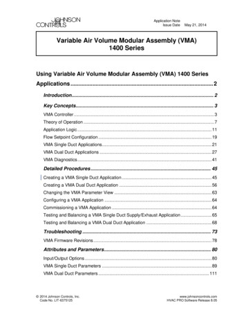
Variable Air Volume Modular Assembly (VMA) 1400 Series Application Note3Key ConceptsVMA ControllerDescriptionThe Variable Air Volume Modular Assembly (VMA) modelsVMA1410 and VMA1420 are integrated modules that include thecontroller, actuator, and differential pressure sensor. The VMA1430includes the controller and differential pressure sensor and is designedfor use with a floating/3-wire (incremental) external actuator orproportional external actuator. The VMA applications are developedusing standard objects, assembly objects and application objectscreated by the Metasys system application basic programminglanguage. These applications are built using Configuration ToolsRelease 7.00 or later, and are downloaded to the VMA. The VMA1430is supported at Configuration Tools Release 7.02 or later.N ote: This document focuses on the VMA1410, 1420, and 1430controllers. The VMA1400 Series also includes the VMA1440, whichis used exclusively as part of the Metasys Zoning Package. Refer tothe Metasys Zoning Package Product Bulletin (LIT-639050) and theMetasys Zoning Package Overview Technical Bulletin (LIT-639100)for information on this specialized product.VMA1410VMA1420VMA1430VMA14xxFigure 1: VMA Controller ModelsVMA applications can only be used with the VMA. These applicationscannot be downloaded to any other digital controllers, such as theUnitary (UNT), Variable Air Volume (VAV), or Air Handling Unit(AHU) controllers.
4Variable Air Volume Modular Assembly (VMA) 1400 Series Application NoteIntegral Stepper Motor ActuatorThe stepper motor damper actuator is an integral part of theVMA1410/1420. The stepper motor provides a fast and accuratemethod of controlling the damper actuator. At startup, the VMA isprogrammed to perform an autocalibration procedure. This procedureoccurs on a variable time delay determined by the N2 address.Autocalibration corrects for pressure sensor drift and ensures thestepper is synchronized. As part of the initial autocalibration, thestroke time of the integral actuator is calculated based on the timerequired to move from the open end-stop to the closed end-stop. Thestroke time should be roughly equal to one of the following: 30 seconds for 90 degree dampers 20 seconds for 60 degree dampers 15 seconds for 45 degree dampersThe VMA requires physical end-stops on both ends of rotation forcorrect operation.During normal operation, the actuator position feedback providesposition information and diagnostics that can indicate a stuck damperor slippage at the damper shaft connection. For the dual ductapplication, the VMA1420 with an integral actuator (if used) must beused on the cold deck damper.External Damper ActuatorsThe VMA1420/30 can control external floating/3-wire (PositionAdjust Output [PAO]) or proportional damper actuators in VAVboxes, such as Trane company boxes. Two Binary Outputs (BOs) areused for each floating/3-wire (PAO) actuator. One Analog Output(AO) is used for each proportional actuator.N ote: External actuators require configuration of the stroke timeattribute for the actuator to operate properly.
Variable Air Volume Modular Assembly (VMA) 1400 Series Application NoteRevisionsTable 1 compares HVAC PRO software revisions and VMAapplication revisions. See the Troubleshooting section of thisdocument for more information on VMA firmware revisions.Table 1: RevisionsHVAC PROSoftware RevisionVMA ApplicationRevisionDescription of Changes7.002Original Release7.013 Units attribute added for flow parameters. State machine fixes to prevent stuck conditions:- VAV Box mode- Heating mode State machine fix to prevent Cooling state when aconstant volume box (maximum flow is achieved duringSatisfied state). Autocalibration Duration is now calculated automatically. Additional actuator support for flow control loop:- Floating/3-wire- Proportional Users must set a new attribute for proportional actuatorsStroke Time.7.0247.034Application fix to correct error in pressure dependentoperation8.00Single Duct – 4Support added for TMZ Digital Room Sensor.Dual Duct – 1Original release of dual duct applicationSingle Duct – 4Supply exhaust application added to single duct application.Dual Duct – 2Application fix to correct error with proportional band resetSingle Duct – 5 State machines moved to sub-application to enable largesupply/exhaust applications to download. Optional minimum flow protection added for proportional(AO, Duration Adjust Output [DAO]) box heating outputs. Schedule attribute added to Occupancy Mode (ADI 78)for network command. If N2 communication fails, theOccupancy Mode Input is the default mode. See the KeyConcepts section for complete description. Setpoint threshold added to enable application to bypassstate machine saturation timers when a large setpointchange occurs. Configurable maximum damper positions added forpressure dependent mode. Pattern Recognition Adaptive Control (PRAC) disabledfor Proportional-Integral-Derivative (PID) control loopsdependent on flow when Starved Box flag is True. Min PID Prop Band limit added to provide a lower tuninglimit for PRAC. Sideloop PID Direct Acting parameter mapped (BD 171)8.018.03Changes to bothapplications:Single Duct – 5Dual Duct – 3Continued on next page . . .5
6Variable Air Volume Modular Assembly (VMA) 1400 Series Application NoteHVAC PROSoftware Revision(Cont.)VMA ApplicationRevisionDescription of Changes8.04Single Duct - 5Support for TE-7700.Changes to bothapplications:Single Duct – 5Dual Duct – 3TMZ setpoint allows wider ranges of 7 to 32 C (45 to 90 F).Note: The TMZ must be at firmware revision A08 or later totake advantage of this feature.Single Duct – 5 Support added for autocalibration using BO activatedsolenoid air valve that zeros the differential pressureacross the velocity pressure sensor(s). VAV Box Mode sequencing updated to ensureapplication remains in heating ,at minimum, for the PIDlow saturation time.8.05Related DocumentationTable 2 lists related VMA documentation.Table 2: Related DocumentationFor Information on ThisRefer ToVMA Product InformationVariable Air Volume Modular Assembly (VMA) 1400 Series ProductBulletin (LIT-635058)VMA Installation InformationVAV Modular Assembly (VMA) 1410/1420 Installation Instructions(Part No. 24-8740-1) - packed with VMA1410 and VMA1420VAV Modular Assembly (VMA) 1430 Installation Bulletin(Part No. 24-8986-18) - packed with productVMA Technical InformationVariable Air Volume Modular Assembly (VMA)1400 Series Overview andEngineering Guidelines Technical Bulletin (LIT-6363120)Mounting and Wiring Variable Air Volume Modular Assembly (VMA)1400Series Controllers Technical Bulletin (LIT-6363125)Downloading and Commissioning the Variable Air Volume ModularAssembly (VMA)1400 Series Controllers Technical Bulletin (LIT-6363130)Troubleshooting Variable Air Volume Modular Assembly (VMA)1400 SeriesControllers Technical Bulletin (LIT-6363135)Commissioning Tool UserInformationHVAC PRO User’s GuideConnecting the N2 BusN2 Communications Bus Technical Bulletin (LIT-636018)
Variable Air Volume Modular Assembly (VMA) 1400 Series Application Note7Theory of OperationVAV SystemA VAV air handling system typically consists of a single air handlingunit and multiple terminal units. Terminal units typically consist of adamper and flow sensing probe installed in an enclosure. VAVterminal units are also called VAV boxes. VAV systems arepredominantly single duct, but about 15% are dual duct designs. Ineither case, the supply air temperature and static pressure of the airhandling unit are controlled by an AHU controller, while each zonehas its own VMA controller.The air handling unit typically maintains a static pressure in the rangeof 125 to 375 Pa (0.5 to 1.5 inches w.c.) inside the longest run of ductaway from the supply fan. This ensures that each VAV terminal unithas enough pressure at its inlet to deliver the maximum required flowof air into the space. The supply temperature is typically in the rangeof 7 to 16 C (45 to 60 F) for a single duct VAV system or the colddeck of a dual duct VAV system. The hot deck temperature of a dualduct VAV system is typically in the range of 29 to 49 C (85 to 120 F).VAV systems are most easily understood by first considering a coolingonly application. As the zone temperature increases, the VAVcontroller opens the VAV box damper to allow more cool air to reachthe space. The volume of air required to maintain a particular zonetemperature setpoint is dictated by the size of the space and theinternal and external heat loads. In addition, since the size of the VAVbox dictates its maximum cooling capacity, a VAV box’s performanceis dependent upon the mechanical engineer’s correct box sizing foreach zone.Sometimes the size, and thus the capacity, of the VAV box may notmatch the zone loads. If the installed unit is too small, insufficientcooling results and audible noise may be emitted at high flow. If theinstalled unit is too large, proper control may be difficult to attain,since a small change in damper position causes a large change inairflow. Boxes can be oversized to allow for quieter operation orreserve cooling capacity at the expense of controllability. For a morein-depth explanation of VAV control, refer to the Variable Air VolumeModular Assembly (VMA) 1400 Series Overview and EngineeringGuidelines Technical Bulletin (LIT-6363120).
8Variable Air Volume Modular Assembly (VMA) 1400 Series Application NoteControl LoopsPressure Independent ControlIn Cooling mode, the VMA employs cascaded control loops. The zonetemperature control loop is achieved by using Proportional-Integral(PI) control loops with Pattern Recognition Adaptive Control (PRAC)to tune the controller. The output of the temperature loop is used tocalculate the airflow setpoint between the minimum and maximumflow settings. This airflow setpoint is used by the flow control loopthat is implemented using the Johnson Controls patentedProportional-Adaptive (P-Adaptive) algorithm. The flow control loopallows the temperature control to be independent of duct staticpressure.Proportional-Integral-Derivative (PID)The Heating, Ventilating, and Air Conditioning (HVAC) industry usesPID feedback control algorithms. The derivative portion is available inthe VMA, but it is typically not used because it can amplify noise andlead to instability. Thus, PI algorithms are most commonly used inactual installations. PI control algorithms have two parameters thataffect controller performance: proportional gain and integral time.The HVAC controls’ manufacturer typically uses default PI controlparameters shipped with the controller. The default parameters maynot be appropriate, and using them can lead to poor controlperformance. Also, many control loops require frequent re-tuningbecause HVAC systems have time-varying dynamics. These dynamicsare caused by the inherent non-linear behavior of HVAC systemcomponents and the time-varying nature of the load disturbances. Theloads for HVAC systems change with time or season.Pattern Recognition Adaptive Control (PRAC)1The VMA uses a Johnson Controls patented PRAC algorithm to tuneits PI feedback loops. The PRAC algorithm automatically adjusts theproportional band and the integral time of a PI control loop based onpatterns of the sensed values from the process variable, setpoint, andthe output of a PID control loop. PRAC uses a measure of the systemdamping and response speed of the process output to characterize theclosed loop response with respect to different setpoint changes andload disturbances, resulting in near-optimal closed loop controlperformance. PRAC automatically adjusts to different process noiselevels, has minimal calculation and memory requirements, and iseasily implemented.
Variable Air Volume Modular Assembly (VMA) 1400 Series Application Note9Using PRAC reduces commissioning time for new control systems,eliminates operator time for re-tuning control loops and increasesactuator life, as it reduces motor runtime.PRAC is used to tune the zone temperature control loop in pressureindependent applications. When two-position valves or electric heat isselected, PRAC is not loaded. PRAC is enabled or disabled via asoftware command. PRAC is disabled at saturation, upon an error, andduring an override situation. If a derivative time value other than zerois detected in a PID control loop, PRAC does not attempt to tune thecontroller.Starting with Application Revision 5 for single duct and ApplicationRevision 3 for dual duct applications, PRAC is also disabled if theactive PI does not have sufficient flow to maintain control (forexample, Starved Box is True). This means that in single ductapplications, the Cooling PID is disabled if Starved Box is True.Similarly, the Box Heating PID for single duct applications is disabledif Starved Box is True and there is no box fan active. In dual ductapplications, the Energy Balance PID is disabled if either Starved ColdDeck or Starved Hot Deck is True.1Seem, J. E., “A New Pattern Recognition Adaptive Controller”,13th Triennial IFAC World Congress, The InternationalFederation of Automatic Control, San Francisco, CA., Volume Kon Adaptive Control, Session on Auto-tuning and Adaptation,Paper 3B-043, pp. 121-126, Pergamon, 1996.P-Adaptive Control2The P-Adaptive flow control algorithm uses a patented fixed gain,proportional control loop with a self-adjusting deadband whose valueis related to an estimate of the noise variance. The P-Adaptive controlstrategy is used in the secondary flow control loop for pressureindependent applications. P-Adaptive control has the advantage ofmuch tighter flow control without oscillation, because it dynamicallyadjusts the flow deadband, based on the turbulence (noise) measuredon the pressure sensor. P-Adaptive does not require any tuning.2Federspiel, c., 1997. “Flow Control with Electric Actuators”,International Journal of Heating, Ventilating, Air Conditioning,and Refrigeration Research, Vol. 3, No 3.
10Variable Air Volume Modular Assembly (VMA) 1400 Series Application NoteAirflow MeasurementAirflow (supply flow) is calculated for the VMA usingtwo parameters: the supply box area (area at the inlet of the box wherethe airflow pickup is located), and the flow pickup gain (supply pickupgain). Appendix B: VAV Controller Flow Calculation Constants(LIT-6375185) provides the flow pickup gain (supply pickup gain) orK-factor for most Original Equipment Manufacturer (OEM) boxes.With this information, the VMA calculates the airflow (supply flow)using the following equation:SupplyFlow SupplyBoxArea * FlowCoefficient *SupplyDeltaPSupplyPickupGainAlternatively, if you know the supply flow and differential pressure(SupplyDeltaP), calculate the flow pickup gain (SupplyPickupGain)using the following equation:SupplyPickupGain FlowCoefficient SupplyBoxArea SupplyDeltaP SupplyFlow N ote:2Exhaust flow is calculated using the same equations.SI (Metric) UnitsSupplyFlow airflow calculated in m3/hr (liters/second in Canada)SupplyDeltaP differential pressure in Pascal (1 inch w.c. 249 Pa)FlowCoefficient defaults to 4644 at sea level for airflow in m3/hr or1290 at sea level for airflow in liters per second (l/s)(These values are a function of elevation.)SupplyPickupGain airflow pickup gain (dimensionless)SupplyBoxArea area in square metersInch-Pound UnitsSupplyFlow airflow calculated in cubic feet per minute (cfm)SupplyDeltaP differential pressure (inches w.c.)FlowCoefficient defaults to 4005 at sea level(This value is a function of elevation.)SupplyPickupGain airflow pickup gain or K-factor (dimensionless)SupplyBoxArea area in square feet. Calculated from 3.1416 * r2,where r is the inlet radius in feet.
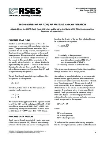
Variable Air Volume Modular Assembly (VMA) 1400 Series Application Note11The engineer or balancing contractor determines the minimum airflownecessary for adequate ventilation. Required minimum airflow isbased primarily on the expected number of occupants in the room. TheAmerican Society of Heating, Refrigerating, and Air ConditioningEngineers (ASHRAE) Standard 62 recommends 34 cubic meters perhour (20 cubic feet per minute [cfm]) of outdoor air per occupant foroffice space. Typically, zone airflow minimums are set between 10%and 20% of maximum flow. Boxes with heat may have higherminimum heating flow setpoints. Boxes with electric heating require aminimum airflow to avoid tripping the thermal overload protection.Application LogicThe VMA operates in several modes. Some modes occur under normaloperating conditions, and some are commanded only by a supervisorysystem. The VAV Box mode determines which PID control loops areactive and controls VMA supervisory Command modes. The currentOccupancy mode determines the current occupancy state. Velocitypressure status and zone temperature status determine the failsoftfunctioning of the VMA.VAV Box ModeThe main mode control is the VAV Box mode. True digital logic isused to determine the active operating mode of the VMA. A statemachine standard object integrates this logic with input and outputfunctions. The operation of a state machine is clearly represented usinga state diagram like that shown in Figure 2. This generic state diagramshows the general form taken by the VAV Box mode state machine inboth the single duct and dual duct VMA applications.State DiagramThe following is a brief explanation of how to read a state diagram.See Figure 2 for a state diagram illustration.A circle represents a state, and its name is listed in the circle. Thenumber in the circle corresponds to the state name in the enumerationset for the present value. A rectangle with a shaded header barrepresents a super-state. A super-state allows related states to begrouped under one heading.Only one state can be active at any one time. The active state is alsothe present value of the VAV Box mode. The present value can changetwo ways. The present value is a prioritized attribute and can beoverridden to a new value. The present value is equal to the overridevalue with the highest priority.
12Variable Air Volume Modular Assembly (VMA) 1400 Series Application NoteWhen no overrides are present, the active state can change via atransition (designated by an arc). Transitions may occur between bothstates and super-states. The arc points from the current state(or super-state) to the next state (or super-state). The next-statefunction is described on each arc. The next-state function must be Truefor the transition to occur. Any input not listed for a particulartransition is a “don’t care” condition, meaning that transition can occurregardless of the current value of any input that is not listed.If the transition leaves from a super-state, the transition can occur ifany of the individual states within that super-state are active. If atransition goes to a super-state, then that super-state must have anentry state defined. This state is designated in the diagram by a largedot with an arrow pointing at the entry state. When more thanone level of hierarchy is defined, a super-state may be defined as theentry state for a higher level super-state.VAV Box ModeCommand Modes01ShutdownClosedShutdownOpenOverride ClosedOverride OpenNo OverridesAuto ModesTransition 223State AState BEntryStateEntryStateTransition 1boxmodeFigure 2: VAV Box Mode State Diagram
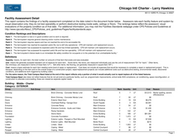
Variable Air Volume Modular Assembly (VMA) 1400 Series Application Note13AutocalibrationAutocalibration first occurs after a reset of the controller. A reset is acycle of the controller power which causes a refresh of the memory. Areset also occurs after an application download. During the firstautocalibration, the integrated actuator fully opens and then fullycloses to measure the stroke time. If needed, you can disable thisautorange test by setting the Startup Autorange parameter to False. Ifyou disable the autorange test, however, you must manually configurethe stroke time for rotations other than 90 degrees (see the IntegralStepper Motor Actuator section under Key Concepts in this documentfor more information).During normal autocalibration, the actuator closes during the actuatorstroke time plus sensor settling time, and then the differential pressuresensor analog input offset adjusts to give a velocity pressure reading ofzero. For the dual duct application, both pressure sensors autocalibrateat the same time.For the single duct supply/exhaust application, when you also select anexhaust box, both pressure sensors autocalibrate at the same time. Dueto the critical flow requirements of most supply/exhaustconfigurations, the autocalibration period default is set to zero to allowthe user to manually command autocalibration (using the Autocal Reqattribute) at a time when the zone is not occupied and the dampers areclosed.Starting with HVAC PRO 8.05 and later, another option is availablefor autocalibration using a BO to actuate a solenoid air valve when thesensor calibration is active instead of closing the damper. Duringautocalibration, the BO is set active for approximately 24 seconds(8 times the On Pulse Count. See VMA Single Duct Parameters). Atthe end of that time period, a new offset calculates for the DifferentialPressure (dP) sensor(s). The flow controller is prevented from movingthe damper actuator while the BO is active and for approximately8 seconds after the BO deactivates. This allows the normal differentialpressure signal to restore before returning control to the flowcontroller. For supply/exhaust applications, both pressure sensorsautocalibrate at the same time. Dual duct applications do not currentlysupport this feature.Install the solenoid in an arrangement similar to Figure 3. When thesolenoid air valve is active and the normally closed port opens to thecommon port, the low-pressure pickup port connects to both ports ofthe dP sensor so that the sensor receives a zero differential pressure.
14Variable Air Volume Modular Assembly (VMA) 1400 Series Application NoteFlowcSolenoid ValvenoncdP SensorDuctFigure 3: Solenoid Air Valve InstallationN ote: The solenoid air valve must accommodate very lowpressures (less than 1.5 inches w.c. [375 Pa]). It must not requirehigher pressures to properly seal or operate.The VMA staggers autocalibration following reset so that severalcontrollers do not autocalibrate at the same time. The autocalibrationdelay is a function of the restart delay. Subsequent autocalibrationoccurs based on the autocalibration period. The default period is twoweeks for normal applications and zero (disabled) for supply exhaustapplications. When using the BO option, configure the autocalibrationperiod to that given in the job specification (typically a 3-hour periodprovides sufficient accuracy).N ote: If the resultant AI offset is large (greater than 1), verify therotation of the VAV Box Damper using Box Flow Test with the AIoffset reset to zero.Occupancy ModeOccupancy mode has three possible states: Occupied, Unoccupied, andStandby (Table 3). The state depends on the input received frombinary inputs, such as window contact, occupancy sensor, ortemporary occupancy button. Communications status with asupervisory system, and commands from a supervisory system to theOccupancy mode request, also affect the Occupancy mode.Table 3: Occupancy ModesModeDescriptionOccupiedWhen the mode is Occupied, the zone temperature and flow ratecontrols use the occupied setpoints.UnoccupiedWhen the mode is Unoccupied, the zone temperature and flowrate controls use the unoccupied setpoints.StandbyWhen the mode is Standby, the zone temperature control usesthe standby temperature setpoints and the flow rate control usesthe unoccupied setpoints.
Variable Air Volume Modular Assembly (VMA) 1400 Series Application Note15Rules for Occupancy ModeOccupancy mode is determined by the following set of rules. If thefirst rule does not apply, then the second rule is evaluated and so ondown the list. Information content and quality are the principles uponwhich these rules are based. The following rules begin with the highestpriority first and involve actions with the most information content,meaning the operator, occupant, or sensor is required to take an action.N ote: For TMZ Digital Room Sensors, refer to Room Sensor withLCD Display (TMZ1600) Installation Instructions (LIT-6363110) fordifferences in operation.1.The Occupancy mode Present Value can be overridden. Thisaction takes highest priority.2.Occupancy Button - Next mode (timed): Unocc - Standby - Occ:Each press of the room sensor Occupancy button changes theOccupancy mode from its current state to the next Occupancymode. For this option, the occupancy status rotation order is:a.Unoccupied(Light-Emitting Diode [LED] off)b.Standby(LED blinks)c.Occupied(LED on)d.Back to Unoccupied, then recycle through all three modesEach button press also restarts the occupancy timer, which isdefaulted to 60 minutes. The Occupancy mode set by thisOccupancy button is cleared when the occupancy timer expires.N ote:You must use a room sensor with an LED for this option.3.Occupancy Sensor - Occ button canceled when unocc sensed: TheOccupancy mode and the occupancy timer set by the Occupancybutton in Rule 2 is cleared if the occupancy sensor goes fromactive to inactive.4.Occupancy Sensor - Occupied mode when occupancy sensed:The Occupancy mode is set to Occupied if the occupancy sensoris active.5.Occupancy Button - Occupied Mode (timed): Each press of theOccupancy button restarts the occupancy timer, which is defaultedto 60 minutes. The Occupancy mode is Occupied when set by anOccupancy button and is cleared when the temporary occupancytimer expires.6.If the Schedule attribute is commanded to a value other than
that is implemented using the Johnson Controls patented Proportional-Adaptive (P-Adaptive) algorithm. The flow control loop allows the temperature control to be independent of duct static pressure. Proportional-Integral-Derivative (PID) The Heating, Ventilating, and Air Conditioning (HVAC) industry uses PID feedback control algorithms.