Transcription
Magnet DesignMagnet Design. USPAS, June 2005Y. Papaphilippou, N. Catalan LasherasUSPAS, Cornell University, Ithaca, NY20th June – 1st July 20051
Parametersz Field needed to bend a particle and force it into a trajectory qvB mv2 / RF q(v B) ma BR mv/ qBR Bρ p/0.2998 for an electron or a proton when p [GeV]z Particle species and energy define the acceleratorz The first decision in the design of a circular accelerator is the trade-offbetween tunnel circumference and magnetic field.Magnet Design. USPAS, June 2005{ Saturated iron magnets. B 2T{ 2T Superconducting technology{ Emittance of the beam and optics define the quadrupole fields. Strengthusually not as stringent.z Field should be linear to the 10-4 level. Transfer function needs to beconstant.2
Magnetic materialsRemember: M χH, B μH μ0(H M)H excitation field, B Magnetic flux, Induction, M Magnetization Permeability μ,susceptibility χMost materials present diamagnetism or paramagnetism. In both cases there is nothysteresis and the magnetization disappears when the external excitation fieldis zeroSpecial materials show ferromagnetism. Minuscule magnetic domains are presentin the material and align in the presence of a magnetic field.Magnet Design. USPAS, June 2005Saturation is reached asymptotically at 0 ºK with no thermal disorder when all thedomains are aligned.μ0MsatCurie Temp[Tesla @ 0 K][ C]Iron2.18770Nickel0.64358Cobalt1.8111203
Magnetic potentialThe Maxwell laws for magneto-statics: . B 0; H j.In the absence of currents j 0 we can express B as the gradient of a scalarpotentialB Φ and 2Φ 0Magnet Design. USPAS, June 2005We get the Laplace equation which has a solution in cylindrical coordinates ofthe form:()Φ Anr n cos(nθ ) Bnr n sin(nθ )nwhere An and Bn correspond to pure skew and normal components4
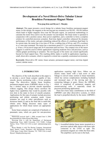
Ideal pole shapez In iron dominated magnets the field is determined by the shape of the steelpoles (lines of constant scalar potential).z Conductor coils are wounded around the poles to create the magnetic field.z Due to boundary conditions, pole surfaces are equi-potential lineDipole (n 1)Magnet Design. USPAS, June 2005Φ(r,θ ) A1r cosθ B1r sinθΦ(x, y) A1x B1 yBx A1By B1Pole: y g / 25
Ideal pole shapeMagnet Design. USPAS, June 2005Quadrupole (n 2)Sextupole (n 3)Φ (r ,θ ) A2 r 2 cos 2θ B2 r 2 sin 2θΦ (r , θ ) A3 r 3 cos 3θ B3 r 3 sin 3θΦ ( x, y ) A2 ( x 2 y 2 ) 2 B2 xyΦ ( x, y ) A3 ( x 3 3 y 2 x) B3 (3 yx 2 y 3 )B x 2( A2 x B2 y )B x 3 A3 ( x 2 y 2 ) 6 B 3 xyB y 2( A2 y B2 x)B y 6 A3 xy 3B3 ( x 2 y 2 )Pole : xy R 2 / 2Pole : 3 x 2 y y R 36
Symmetriesz Dipole:Φ (θ ) Φ (2π θ )Φ (θ ) Φ (π θ )only Bn with n 1,3,5, etc.z Quadrupole: Φ(θ ) Φ(π θ ) Φ(θ ) Φ(2π θ )Φ(θ ) Φ(π / 2 θ )Magnet Design. USPAS, June 2005only Bn with n 2,6,10,etc.z Sextupole: Φ (θ ) Φ (2π / 3 θ ) Φ (θ ) Φ (4π / 3 θ ) Φ (θ ) Φ (2π θ ) Φ (θ ) Φ (π / 3 θ )z In practice poles have a finitewidthz Impose the same symmetries tothe pole ends to constrain theharmonicsz Longitudinally, the magnet endwill generate non linear fringefields Î shimsz Sharp edges will cause saturationand the field becomes non linearÎ chamfered endsz Numerical methods applied todefine the shape and machinedwith high precision.z only Bn with n 3,9,15,etc.7
Dipole currentB is constant around the loop l and in the gapAccording to Ampere’s law H ds J dAAHiron l Hgap g NI1Magnet Design. USPAS, June 2005with μr »1μo μrBiron l B 1μ0B g NIμ0 NIgThe number of conductors and currentdensity can be optimizedLimited by the iron saturationB 2T8
Quadrupole currentB is perpendicular to ds along path 3In path 1Again using Ampere’s law H ds H1 ds H 3 ds NI13The gradicnt G in a quadrupole isMagnet Design. USPAS, June 2005Bx Gy; B y GxH2 Gμ0x2 y2 Gμ0rand we getG 2 μ 0 NIr029
Practical problemsz The finite pole width creates nonlinear errors.z To compensate we add small stepsat the outer ends of each of the polecalled shims.z Saturation at the corners at thelongitudinal end also creates highorder multipolesz Chamfering is done usingnumerical calculationsMagnet Design. USPAS, June 2005z Eddy currents oppose the change ofmagnetic field. They create lossesz Eddy currents in the coil areminimized by transposing theconductors in the coil.z Eddy currents in the yoke areavoided using laminations10
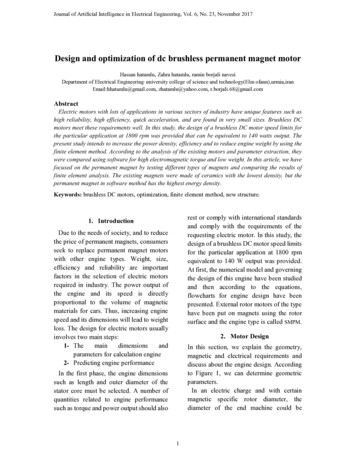
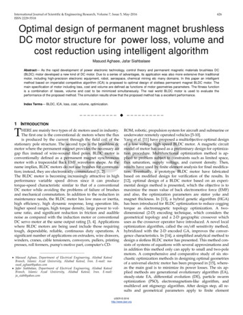
Example: MQWA quadrupolez Twin aperture quadrupole for LHCEva Boter SL-Note-2002-010-MSbuilt in collaboration with TRIUMFby Alstom, CANADA.z Pole geometry is identical in the nosez Disposition of coils around the polesis non symmetric.z Field calculations require numericalMagnet Design. USPAS, June 2005methods done with Opera.11
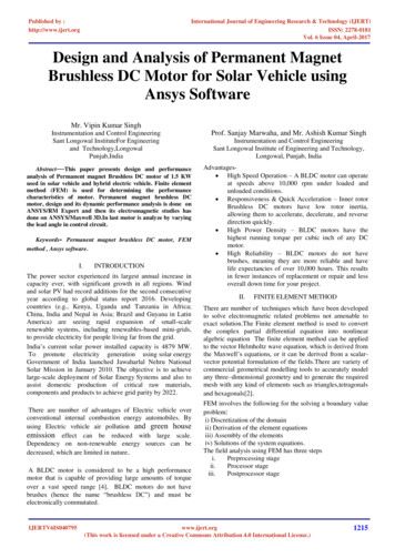
Superconductivityz Superconductivity was discoveredin 1911 by H. Kamerlingh Onnesz The temperature at which thempTeeturare)(KField (Tesla)transition takes place is called thecritical temperature Tcz Phase diagram (NbTi). Thez Under the surface the material hasno resistanceMagnet Design. USPAS, June 2005z Type I and Type IIsuperconductorsCurrent density (kA.mm-2)critical surface.12
Meissner effect in Type I superconductorsz In 1933 W. Meissner and R.Ochsenfelddiscovered what is called the Meissnereffectz The magnetic field is expelled from thesample when it becomes superconducting.z In strong fields the material goes to normalstate.T z Meissner effect is not total, the magneticfield actually penetrates a small distance lthe London Penetration Depth.z Current is limited to a small surface 20Magnet Design. USPAS, June 200550 nmtypically for NbTi if T 10 K0.24TBc z The total current is not large enough tocreate a strong magnetic field.z Type I superconductors are not suitable formagnet coils13
Type II superconductorsz Type II superconductors have a second critical Bc2 (T) Bc1(T)z Magnetic field lines penetrate the superconductor in the form of flux tubesz When B increases more and more flux tubes penetrate the materialz However in the presence of a current,flux tubes move transversely and thismotion generates heatz Introduce flux-pinning centersMagnet Design. USPAS, June 2005(eg. lattice defects). A very delicateindustrial process.z When the external field decreasesflux is trapped creating hysteresis.(diamagnetic). Needs to warm up themagnet14
Magnet Design. USPAS, June 2005Superconducting materials15
Persistent currentsz Currents are produced to counteract a change in magnetic fieldz In the copper, eddy currents are minimized by twisting and transposing thestrands in the cableMagnet Design. USPAS, June 2005z However in the SC they do not decayz This persistent currents produce magnetic effects which can be detectedoutside the cable.z In order to reduce magnetization effects, all magnet conductors are madewith the superconductor divided into fine filaments.z for NbTi is 50 μm, for accelerator magnets 6-10 μm16
Practical superconductors Iz NbTi has been developed since many years and can be industrially produced inlarge quantitiesz Nb3Sn is a promising candidate but it is very brittle what makes windingdifficult.z Rutherford cable is the most common used cable in acceleratorsMagnet Design. USPAS, June 2005StrandsCableFilamentsStrands17
Practical superconductors IIz Due to their crystalline structure HT superconductors are highly anisotropicand only conduct in a tiny surfacez Conductors are made outof a superposition of HTS tapez Used in LHC to manufacture current leadsMagnet Design. USPAS, June 2005z Other high temperature superconductorsas MgB2 made the object of intensive research.18
Biot-Savart lawMagnetic potential in the point P created byan infinite line current IμIAz (r , θ ) 02π n1 r cos[n(φ θ )] n a n 1Magnet Design. USPAS, June 2005 Azμ0 I r Bθ r2πa n 1 a n 1μ0 I r 1 ArBr r θ2πa n 1 a cos[n(φ θ )]n 1sin[n(φ θ )]A single line current produces onlytransverse field but multipole fields of anyorder.19
Distribution of currentAssume a distribution of current with the following shapeI (φ ) I0 cos(mφ)Introducing the potential from a current lineμ0 I0 1 r 2πAz (r,θ ) cos(mφ) cos[n(θ φ)]dφ 2π n 1 n a 0nUsingMagnet Design. USPAS, June 2005cos[n(θ φ)] cos(nθ ) cos(nφ) sin(nθ ) sin(nφ)And using the ortogonality of the trigonometric functions we obtainμ0 I0 1 r mAz (r,θ ) cos(mθ )2 m a A pure multipole of order m!20
cosφ magnetsz The yoke is now far away from themagnet center.z The field quality is determined bythe current densityz By using cos(mφ) currentdistributions we can generate puredipoles, quadrupoles andsextupolesz Intercepting ellipses also create aMagnet Design. USPAS, June 2005uniform field21
Coil with dipole symmetryz For any line current I, it will exist three other currents –I at φ π/2 and φ πMagnet Design. USPAS, June 2005and I at -φ2μ0 In1 r Az (r,θ ) cos(nφ1) cos(nθ ) π n 1,3,5 n a z A coil with dipole symmetry produces only odd normal multipolesn 12μ0 J1 r Bn Δa cos(nφ1 )πn a z By taking φ1 60, the sextupole term n 3 vanishes!!22
Practical geometryz In practice, coils are winded from realcable with an approximate rectangularsection.z Several shells or layers approximatethe cos(mφ) distribution.z The symmetries seen before arerespectedz Errors are reduced by introducingwedgesMagnet Design. USPAS, June 2005z Numerical methods are required toachieve the required main field andminimize the other harmonics.23
Influence of the iron yokez Magnetic field lines return inside the yokez The magnitude of the main magnetic field in the center of the magnetincreases 10-20%z Image methods are used to calculate the total effect.z Does not work at saturation where transfer function is not longer linearMagnet Design. USPAS, June 2005z Numerical methods need to be used in that case24
Numerical methodsz Codes like Roxie, Mafia,Magnet Design. USPAS, June 2005Superfish etc. are used in order tocalculate position the coils, ends,calculate the harmonics, forces,stored energy etc.25
Mechanic constraintsz Lorenz forces act upon the coilswhen powered. LHC dipoleFx 1.6 106 N/m 160tons/mz The different materials fromwhich the magnet is made, havedifferent shrinking coefficientsz Coils may become loose incryogenic conditionsMagnet Design. USPAS, June 2005z Large pre-stress of the order ofMPa is is needed to avoid smallmovements during operation.z Also harmful multipoles whencoils are displaced.z Coils, shrinking cylinders, weldsunder pressure, impregnation,pancakes 26
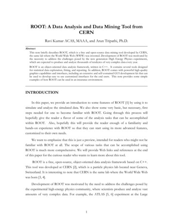
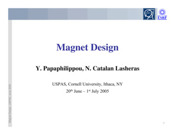
Operating loadline4000Magnet operates in a load line where fieldis linear with current densityresistive30002Current density (A/mm )7Current density kAmm-265432Magnet Design. USPAS, June 2005p ermte Kreatu8102000magnetaperturefieldmagnetpeak field10001046superconducting224F ield T068101214246Field (T)810temperature rise may be caused by- ac losses- poor joints- beam energy deposition-etc, etcThe load line automatically changes27
Quench propagationQuench propagationQuench protection:z A normal conducting zone appears inz detect the quench electronicallythe SC where heat is generatedz If heat is conducted out of thecontact with the windingz this quenches other regions of themagnet, effectively forcing thenormal zone to grow more rapidly(higher resistance, shorter decaytime ,lower temperature rise at thehot spot)resistanceMagnet Design. USPAS, June 2005 resistive zone faster than it isgenerated, the zone will shrink - viceversa it will grow. MPZ minimumpropagating zoneinternal voltages much greater thanterminal voltagez power a heater in good thermaltime28
Magnetic Measurementsz To preserve dynamic aperture of the beam during hours of operationz To accept large beams within a large linear regionz In both normal and superconducting magnets, magnetic field needs to beMagnet Design. USPAS, June 2005linear to the 10-4 level!!FerromagneticSuperconductingz Pole endsz Coil endsz Iron saturationz Persistent currentsz Decay and Snap-backz Saturation of the yokez Magnetic field and harmonics need to be measured with a 10-6 precision29
Nuclear Magnetic ResonanceNMR Nuclear Magnetic resonanceFrom A. Jain CERN Academic trainingz A particle with a net spin placed ina magnetic field of strength B hastwo energy levels.z The energy gap between levels isproportional to the field and thegyromagnetic ratio, γ of theparticle.Magnet Design. USPAS, June 2005z A resonant absorption of RF energyoccurs at a frequencycorresponding to energy gap.ΔE γh BBut Field must be stable and very homogeneous!!30
Hall effectHall probez Charge carriers experience aLorentz force in the presence of amagnetic field.z This produces a steady statevoltage in a directionperpendicular to the current andfield.Magnet Design. USPAS, June 2005VHall GRH I BcosθG geometric factorRH Hall coefficientHowever, the response of the Hallprobe to the field direction is verycomplex!!31
Flux measurementsRotating coilsz A change of flux in the coilinduces a voltage.tend V (t) Φend Φstarttstartz By using a rotating coil we makeMagnet Design. USPAS, June 2005sure thatΦ end Φ start32
Rotating coilz Remembern r [Bn sin(nθ ) An cos(nθ )]Br (r,θ ) n 1 Rref n r [Bn cos(nθ ) An sin(nθ )]Bθ (r,θ ) n 1 Rref Magnet Design. USPAS, June 2005 Radial coil sensitive to the azimuthal fieldTangential coil sensitive to the radial field33
Signal induced in a radial coilzThe signal produced in a radial coil will be RV(t ) NLRref ω 2 Rrefn 1 n R1 R ref n [Bn sin(nωt nδ ) An cos(nωt nδ )] N number of turnsL lengthδ angle at t 0Magnet Design. USPAS, June 2005ω angular velocityφ ωt δThe periodic variation of coil voltage is also described by a Fourier series,whose coefficients are related to the Normal and Skew harmonics, thegeometric parameters of the coil, and angular velocity.34
Bibliography“Materials”, J. Billan in “CERN Accelerator School : Magnetic measurementand alignment” CERN 92-05“Conventional Magnets”, N. Marks in “CERN Accelerator School: 5thGeneral accelerator physics course” CERN 94-01“Superconducting Accelerator Magnets” K.-H. Mess, P. Schmuser, S. Wolff,World scientific ISBN 981-02-2790-6“Superconducting magnets”, M. Wilson, Oxford Science Publications ISBN 019-854810-9Magnet Design. USPAS, June 2005“Superconductivity”, P. Schmuser, in “CERN Accelerator School:Superconductivity in particle accelerators” CERN 96-03“1st International Roxie Users Meeting and Workshop”, CERN 99-01“Magnetic Field Measurements and Mapping Techniques”, A. Jain CERNAcademic training program. 200335
M agnet Des i gn. USPAS, June 2005 2 Parameters zField needed to bend a particle and force it into a trajectory BR Bρ p/0.2998 for an electron or a proton when p [GeV] zParticle species and energy define the accelerator zThe first decision in the design of a circular accelerator is the trade-off between tunnel circumference and magnetic field.