Transcription
Macleod ‐ Thin Film Optics1
A light wave is a propagating electromagnetic disturbance. The electromagnetic nature ofli h was establishedlightbli h d bby James ClClerkk Maxwellll iin theh 19th century butb alreadyl d theh wavenature had been established and interference was well understood.The effects we are interested in are linear. Linear means that if we have two separatestimuli and two separate responses then the response to the sum of the two stimuli will bethe sum of the separate responses. The important implication is that we can then breakany arbitrary light wave into a set of simpler components and follow them separately.Usually we will use a set of plane harmonic (or monochromatic) waves that we call thespectrum. Fourier theory allows us to do this theoretically but there are also all kinds oftechniques that permit us to perform the decomposition experimentally. Each spectralelement, or component, has a sinusoidal profile and can then be treated separately. Weusually assume in our calculations a continuous spectrum of equal energy components andwe do this more or less automatically without really thinking about it.In linear media the frequency of the wave remains constant but traditionally we havealways used wavelength to characterize the wave. Since the velocity varies with themedium, but is always constant in vacuo, the vacuum wavelength is used. Then the actualwavelength is λ/n where λ is the vacuum wavelength and n the refractive index.We use the term polarization to describe the direction of the electric and magnetic fields.Plane or linear polarization is most common and implies that the direction remainsconstant as the wave propagates – although, of course, it reverses during each half cycle ofthe oscillation. Polarization becomes important when we deal with coatings at obliqueincidence.Macleod ‐ Thin Film Optics2
Interference is simply the addition of the fields of the various waves involved. If it involvestwo waves that are plane harmonic of identical frequency and polarization (that is theorientation of the fields) and are propagating in the same direction, then, if they arecoincident in phase, the resultant amplitude is the sum of the individual amplitudes, andwe call this constructive interference. If the fields are in antiphase, then the amplitudessubtract, and we call this destructive. These are the two extreme cases.Macleod ‐ Thin Film Optics3
Most optical systems consist, at least partly, of a series of optical surfaces formed in somesuitable material. Their shape is chosen correctly to manipulate the light. However it is rareto find that the specular properties (mirror‐like properties obeying the law of reflection andthe law of refraction) that are determined by the optical properties of the medium and ofthe worked material, are acceptable. Modification of these properties is the primaryfunction of an optical coating. However, since the coating is normally on the outside of thecomponent it is often expected to perform other functions like limiting corrosion andincreasing abrasion resistanceresistance. The coating usually consists of one or more thin films ofmaterial with composition and thickness chosen to give the correct optical propertiesthrough a mixture of interference and the natural optical properties of the materials.Macleod ‐ Thin Film Optics4
Coatings are usually manufactured by condensation of a suitable vapor under vacuum. Thedifferent processes vary in the way in which the vapor is produced. In thermal evaporationthe material is heated until it boils or sublimes. In sputtering it is produced by bombardinga target by energetic ions. Machines are complex and expensive. Because of this cost, andbecause the coating process is often the final one for an already expensive component,yield is of great importance.Macleod ‐ Thin Film Optics5
Mirrors were probably the earliest optical instruments. They existed all over the world anddate back to prehistory. Lenses came a little later and, in the beginning, were used mainlyas burning glasses. Interference colors were possibly recognized because there are manyexamples in nature, but the mechanism was neither known nor studied. The ancientsdivided materials into opaque materials that simply reflected, and materials thattransmitted light to some extent.Macleod ‐ Thin Film Optics6
We usually classify our materials as metallic or dielectric. Metallic materials transmit little,unless very thin, and usually reflect quite strongly. Dielectric materials are essentiallytransparent. In thin film optics we will usually include semiconductors in the classificationof dielectric. The transparent dielectrics support interference in thin films. The short‐waveoptical properties are dominated by electrons. The positively charged parts of moleculesbecome important further into the infrared.Macleod ‐ Thin Film Optics7
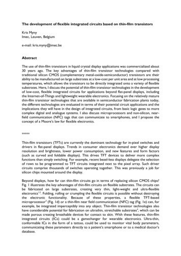
Imagine a dielectric substrate carrying a dielectric film in an incident medium also ofdielectric material. The film will support multiple‐beam interference as illustrated. Let thefilm be exceedingly thin so that the reflectance is exactly what we expect from an uncoatedsurface but the multiple beams still exist in the film and are adding up to that reflectance.Now let the thickness of the film be increased by one half wave. The first beam returning tothe front surface now has an increase in its path of one wavelength and so the earlierphase condition is undisturbed. The next beam will acquire an extra two wavelengths andso on.on It is easy to see that all the phase conditions are completely undisturbedundisturbed. Since thereis no loss, the interference condition is identical to that of the vanishingly thin layer so thata half wave thickness of material, or a whole number of half waves, yields the reflectanceof the uncoated substrate. Halfway between the half waves, when the film is an oddnumber of quarter waves thick, the phase condition is perturbed to a maximum extent andso there is a significant change in reflectance. The formulae for reflectance in both casesare shown. They represent the extreme interference conditions. Other thicknesses giveresults in between these two limits.Macleod ‐ Thin Film Optics8
Most optical coatings have more than one layer. Some have hundreds of layers. Theinterference calculations in such cases can be very complicated and are invariably carriedout these days by computer. But it was not always so and much use is still made ofquarterwave and halfwave films because they are straightforward to understand and theyrepresent the extreme interference conditions.Macleod ‐ Thin Film Optics9
Simple optical surfaces reflect a portion of the light. This can be a problem because notonly is the desired light reduced, but also the reflected light is not lost, but just goessomewhere else. Somewhere else can often be the image plane, where it causes ghostimages and veiling glare. Most simple optical surfaces, therefore, are treated with aantireflection coating. The least complex is a quarterwave of magnesium fluoride thatreduces the reflectance of glass as shown. Ideally we would like a material of still lowerindex but magnesium fluoride is the best we have. In very simple systems this single layercan often be enough and so this coating is still produced on an enormous scalescale. Howevermore demanding systems require better performance and two common multilayer coatingsare also shown. The four‐layer one is usually preferred because it uses two materials only.In practice the layer thicknesses in the four‐layer are adjusted very slightly from the valuesshown to optimize the performance. These coatings are intended for the visible region,400nm to 700nm. Antireflection coatings are required and manufactured over the wholeoptical spectrum. The greater the region over which reflection reduction is required, themore complex and difficult the design and the manufacture, and so the region of bestperformance is invariably limited to some extent.Macleod ‐ Thin Film Optics10
Particularly in Europe and in Asia, spectacle lenses are usually antireflected. This reducesglare, especially in night driving, but also avoids the flare that is often seen from uncoatedspectacles and masks the eyes in a photograph. Such effects become still more acute withthe high index plastic lenses, like polycarbonate, that are gradually replacing the lowerindex materials. The usage in the United States is increasing, but is still lagging behindother regions in uptake. Here we have a demonstration of an antireflection coating on ablank lens, but, so that the performance can be readily gauged, limited in its coverage tothe logo of the company that produced itit. There is some residual color thatthat, strictlyspeaking, is a performance defect but is presented by ophthalmic companies as a feature.The color has become an important fashion statement that is actually strongly desired bythe customer.Macleod ‐ Thin Film Optics11
Here we have an antireflection coating on the objectives of a binocular telescope. Thisparticular coating is known as a ruby coating and in display units in stores there is often aspotlight to illuminate the coating that then appears to glow and look very powerful. Theruby color is produced intentionally in the design that is actually more complicated than asimple antireflection coating. It is applied for two main reasons. One is connected withsales, because the ruby coating seems more scientific and impressive than a less colorfulone. Another is that the spectral range is reduced and so the requirements on chromaticaberration relaxedrelaxed. High‐endHigh end binoculars have a broader and less spectacular coating as dobetter camera lenses.Macleod ‐ Thin Film Optics12
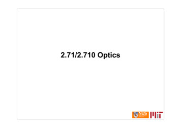
Although high performance metals reflect strongly they still have significant absorptionlosses and many applications require higher performance. We can achieve exceedingly highreflectance over a limited region using a stack of quarterwaves of alternate high and lowindex. At the wavelength for which the layers are exact quarterwaves, all the multiplebeams emerging from the top surface to form the reflected beam are exactly in phase, andthe interference is maximum constructive. The width of the high reflectance zone isrestricted and the higher the ratio of high to low index the broader is the region, but it isalways rather restrictedrestricted. Obviously at one half of the design wavelength the layers becomehalfwaves and their interference effects vanish. The high reflectance repeats at one thirdand one fifth, and so on, of the fundamental wavelength. Laser mirrors are commonly ofthis design. The horizontal scale in this diagram is normalized so that the performancedetails can easily be seen. The next slide shows a more usual plot.Macleod ‐ Thin Film Optics13
Here we plot the characteristic of a typical quarterwave stack in the visible region as afunction of wavelength. It covers only part of the region. By using more layers andstaggering their thicknesses we can extend the width to cover the whole of the visible butfor really wide high‐reflectance coatings we still must make use of metal layers especiallyaluminum.The characteristic curve on the right is of a longwave pass filter based on the quarterwavestack Longwave pass and shortwave pass are commonly referred to as edge filters.stack.filters Theresidual fringes outside the main reflecting region are usually referred to as ripple and theripple can be reduced by a process of matching which is not unlike the addition of anantireflection coating but of more complicated design and invariably the product of anautomatic computer process. The big advantage of the interference edge filter is that it canbe positioned at will simply by altering the thicknesses of all the films in the same ratio.If the edge filter is used as a beam splitter to separate two spectral regions then it isreferred to as a dichroic beam splitter (even if its performance is in the infrared orultraviolet).Macleod ‐ Thin Film Optics14
Here are some color separation filters that are based in their design on the quarterwavestack but with the ripple‐reducing additions. The colors shown are in reflection and, sincethere is no loss, the colors in transmission will be complementary. Thus the top row showssubtractive primary colors but those in transmission will be additive, and vice versa for thelower three.Macleod ‐ Thin Film Optics15
A halfwave, or multiple halfwave, layer surrounded by two equal quarterwave stacks, yieldswhat we call a tuned cavity. It has the property of high transmittance at the referencewavelength, where the layers are halfwaves or quarterwaves, and high reflectanceelsewhere. Thus it acts uin transmission as a narrowband filter. The sides of the passbandcan be steepened by adding further cavity structures as shown. Such filters are used in anenormous range of applications in the ultraviolet, visible and infrared. The design principlesare the same in all regions but the useful materials differ. The design notation used here isa common one where a quarterwave layer is indicated by a capital letterletter. If there are onlytwo materials an H for a high‐index quarterwave layer and L for a low index are commonsymbols. LLLL then indicates a thickness of four quarterwaves of low index, or one fullwave, and can also be written as 4L.Macleod ‐ Thin Film Optics16
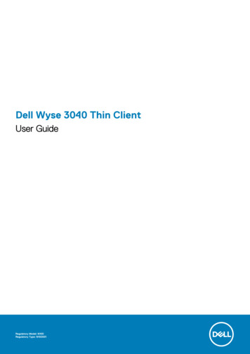
An important application for multiple‐cavity narrowband filters is in multiplexing anddemultiplexing of the optical channels in optical fiber communication. We can think of thecomponent as a four‐port device. The signal at the in port consists of many equally‐spacedchannels. All of these, with the exception of the chosen channel at the filter peak, arereflected to the through port. The chosen channel continues through the filter to the dropport. A replacement channel at the same frequency can be added to the others through theadd port. Because of the exceedingly tight requirements on leakage between the add anddrop channels,channels what is called coherent crosstalkcrosstalk, the full four port configuration is rare.rareUsually it is limited to three ports. The use of two three‐port configurations satisfactorilyreduces the coherent crosstalk. The design and production of such filters is an exacting taskand specially designed coating machines are used. To make the design notation morecompact we write repeated structures as (HL)7 or (HL) 7 which indicates that the structurewithin the brackets is repeated seven times.Macleod ‐ Thin Film Optics17
Aluminum replaced silver as the coating of choice for astronomical telescopes in the1930’s. In a curious reversal, silver is making a comeback. The reason is largely in theinfrared. Silver has a higher reflectance than aluminum (silver has the highest reflectance ofall metals) and so its emissivity is lower. The emittance of the mirror surfaces is the majorlimitation to the detectable weakness of infrared sources. Unfortunately silver is much lessenvironmentally resistant than aluminum and so must be protected by the surroundingnitride films that render the production of the coating much more demanding than simplealuminizing There are two Gemini telescopesaluminizing.telescopes, one in Hawaii and one in Chile and togetherthey cover the entire sky. Their primary mirrors are 8.1 metres in diameter. A linearmagnetron source is a special kind of sputtering source.Macleod ‐ Thin Film Optics18
Heat loss in the winter and heat gain in the summer through glazing puts considerablestrain on building temperature control systems and can be costly. Most advanced countrieshave regulations that require the use of energy‐saving glazing in the construction of publicbuildings. The coatings, in terms of the number of layers, are simple, but their production isexacting and there are strict specifications on color and throughput. Different colors areavailable, but architectural and aesthetic considerations demand that it does not varyperceptibly in any single building. The coatings are based on silver. It is possible toantireflect thin silver layers so that they transmit well in the visible region but reflectstrongly in the infrared where the antireflection performance falls off. The global demandfor low‐E coating is currently estimated to be in excess of 1 billion square metres perannum. The lists of layers in the designs omit the very thin diffusion barrier layers that areinserted on either side of the silver layers. They usually consist of a nanometre or so ofactive metal that is allowed to oxidize in situ. Nickel, titanium, chromium are typical metalsused for this.Macleod ‐ Thin Film Optics19
All kinds of different coatings are combined with light sources. Some are for colorcorrection, especially to render light more like daylight. Here is an example of a coating thatincreases the efficiency of a filament‐based lamp by directing the heat content back to thefilament. Although the silver‐based coatings shown earlier present useful characteristicsthey do not have sufficient resistance to the high temperatures of the lamp envelopes andso the lamp coatings have to be based on refractory dielectric materials. The designs aretherefore much more involved.Macleod ‐ Thin Film Optics20
It has been known for several centuries that internal reflection in a dielectric material atsufficiently high angles of incidence is total. More recently it has been found that whenmetal layers are added to the totally reflecting surface, light that is polarized with theelectric vector in the plane of incidence (p‐polarization) behaves in a strange way. Providedthe metal is of the correct thickness, which depends on the optical properties of the metal,the total p‐reflectance can fall to zero in a quite narrow resonance‐like feature. Silver andgold give very narrow reflectance dips and they are much used in this application. The dip isassociated with a propagating electromagnetic wave that is pinned to the outer surface ofthe metal and is very sensitive to surface conditions. The wave is properly called a surfaceplasmon polariton but the resonance is usually known simply as a surface plasmonresonance. The sensitivity to surface conditions makes the resonance move in angle wheneven very small amounts of material are added to the surface and so it can be used as anextremely sensitive detector of material. There are many applications.Macleod ‐ Thin Film Optics21
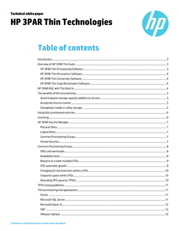
The surface plasmon resonance can be used in biochemistry and in medicine to detectspecial proteins and pathogens through a process known as binding. The outer surface ofthe metal is treated with receptors to which the protein or pathogen to be detected willbind. The binding increases the thickness of the film on the metal surface and moves theresonance. Very small amounts of specific material can be detected in real time. The highangle of incidence in the example is because the outer medium is assumed to be waterwhereas in the previous example it was assumed to be air. Such techniques are alreadybeing commercially exploitedexploited.Macleod ‐ Thin Film Optics22
The sketch shows the electric field of a short pulse. The pulse consists of an envelope ontop of a carrier. If we could actually see the pulse like this we would probably notice thatthe carrier is moving at a different velocity from that of the total pulse. They will movetogether only in a vacuum. The pulse velocity, which is that of the envelope, is known asthe group velocity and that of the carrier as the phase velocity. These are old terms with along history and we still use them. Because we are dealing with linear effects we canrepresent the pulse as a spectrum of harmonic components. Pulses that have a time lengthmeasured in femtoseconds (10‐15 seconds 1 femtosecond) are known as ultrafast andrepresent a growing field of research and application. Light in a vacuum travels at around300 nanometres in 1 femtosecond. This means that when the pulse illuminates an opticalcoating of any complexity, the pulse reflected from the rear surface lags significantly behindthat reflected from the front so that all kinds of interesting effects occur. Incidentally,although telecom optical pulses are measured in picoseconds, the coatings involved intelecom are so complex that similar effects occur there and have to be taken into account.Macleod ‐ Thin Film Optics23
Fortunately we are still dealing with linear effects and so can represent the pulse by itsspectrum. Here we represent the spectrum in terms of frequency and distance at aparticular time. The phase is denoted by the colors and the peak of the pulse is situatedwhere there is a coincidence in the value of phase across the whole spectrum. By alteringthe phases of the components without altering their amplitudes we can actually changethe position of the pulse and even its shape. The important aspect of the change in phase isits variation as a function of the angular frequency, ω. A constant derivative of phase withrespect to ω will tilt the lines of constant phase with the result that the time of arrival ofthe pulse will change. A second derivative implies that the top part of the distribution tiltsthe phase lines in the opposite direction from those below. The result is that the bottompart of the diagram shows a phase coincidence at a different position from the phasecoincidence for the top part. At each of these phase coincidences the other part of thedistribution has phases so jumbled that the fields cancel out. This means that the pulsestarts at one position with one carrier and ends at another with a carrier of differentfrequency. The pulse is said to be broadened and chirped. An important application ofoptical coatings is to cancel out the broadening and chirping of a pulse that has beenbroadened and chirped by some other mechanism. The first three derivatives of phase withrespect to ω are the most important ones.Macleod ‐ Thin Film Optics24
Here the first three derivatives (note the minus signs) are shown with the names that areassigned to them. Phase is something we can manipulate in the design of the coating but itis important to note that we are unable to defeat nature. Although a negative group delaymeans that a pulse arrives sooner it is not possible to design a coating where the pulse willturn around in reflection before it reaches the mirror. The specification can readily bewritten but coating design techniques simply fail to yield a suitable result.Macleod ‐ Thin Film Optics25
This is an example of a coating designed to present a group delay dispersion of ‐500 fs2over a given spectral range. Depending on frequency, the light reaches a certain depth inthe coating and that effect, as well as the behavior of certain resonators, delays itsreemergence so that the phase at that particular frequency is altered accordinglycompared with all the other frequencies. Mostly the coatings are designed by automaticcomputer methods because analytical approaches are very involved and difficult.Production requires exception layer accuracy and there can be serious variations in thecharacteristic as a resultresult. A trick that is frequently used is to have multiple reflections at aseries of coatings chosen so that errors in one characteristic are cancelled by oppositeerrors in another. This involves a mixing and matching operation and relies on the linearnature of the processes.Macleod ‐ Thin Film Optics26
Interference effects depend on path differences and path differences depend onpropagation angle. Thus we find that the characteristics of optical coatings vary with angleof incidence. The two most important and common effects that increase with angle ofincidence (roughly a cosine effect) are first a shift of the characteristic to shorterwavelengths and second a splitting of the characteristic where the p‐characteristicbecomes weaker and the s‐characteristic becomes stronger. P‐polarization is the linearmode where the electric vector is in the plane of incidence that contains the ray directionand the surface normalnormal. S‐polarizationS polarization is the linear mode with the electric vector normal tothe plane of incidence and, therefore, parallel to the surface. The s comes from theGerman senkrecht meaning perpendicular. Sometimes there is a third effect, distortion ofthe characteristic. This third effect depends very much on the design details.Macleod ‐ Thin Film Optics27
Optical coatings can be very colorful and we can use the tilting effect to add a dimension tothe color not available in dyes. Here we have a coating deliberately designed to present alarge color shift with incidence. It is used in many decorative applications and also as adouble‐sided coating ground into fragments to form a color‐variable pigment that can beused in inks and paints. A major application of a color‐variable ink is in forgery prevention.Many countries, including the United States, use features printed in color variable ink oncurrency notes to defeat forgery by photocopying.Macleod ‐ Thin Film Optics28
This is a photograph of a painting by David Cushing produced by varying thicknesses andlocal angle of incidence of an optical coating. The substrate is aluminum foil. Anotherexample by David Cushing hangs on one of the floors of the West Wing of the MeinelBuilding of Optical Sciences.Macleod ‐ Thin Film Optics29
This is simply a bit of fun where a calculated color strip showing the colors of oil on water issuperimposed over an actual photo of the colors of an oil slick on a puddle on a road. Theagreement is close.Macleod ‐ Thin Film Optics30
There is much more to optical coatings than can be covered in an hour or so. Thin‐filmoptics is one of the oldest divisions of optics but also one of the newest because opticalcoatings are a necessary feature of virtually every branch of optics technology. Whereverthere is optics there will be an optical coating.Macleod ‐ Thin Film Optics31
of dielectric. The transparent dielectrics support interference in thin films. The short‐wave optical properties are dominated by electrons. The positively charged parts of molecules become important further into the infrared. Macleod ‐Thin Film Optics 7