Transcription
Hardware Reference GuideHP t610 Series Flexible Thin Clients
Copyright 2012 Hewlett-PackardDevelopment Company, L.P. The informationcontained herein is subject to changewithout notice.Microsoft and Windows are trademarks ofMicrosoft Corporation in the U.S. and othercountries.The only warranties for HP products andservices are set forth in the express warrantystatements accompanying such products andservices. Nothing herein should beconstrued as constituting an additionalwarranty. HP shall not be liable for technicalor editorial errors or omissions containedherein.This document contains proprietaryinformation that is protected by copyright.No part of this document may bephotocopied, reproduced, or translated toanother language without the prior writtenconsent of Hewlett-Packard Company.First Edition (March 2012)Document Part Number: 680668–001
About This BookWARNING! Text set off in this manner indicates that failure to follow directions could result in bodilyharm or loss of life.CAUTION: Text set off in this manner indicates that failure to follow directions could result in damageto equipment or loss of information.NOTE: Text set off in this manner provides important supplemental information.iii
ivAbout This Book
Table of contents1 Product features . 1Standard features . 1Front panel components . 1Rear panel components . 3Installing the rubber feet . 4Installing the stand . 4Removing the stand . 5Using the power cord retention slot . 6Using the keyboard . 6Windows logo key . 8Additional function keys . 8Special mouse functions . 8Serial number location . 92 Hardware changes . 10General hardware installation sequence . 10Removing and replacing the side access panel and metal side cover . 11Removing the side access panel . 11Removing the left metal side cover . 12Replacing the left metal side cover . 13Replacing the side access panel . 13Removing and replacing the battery . 14Installing thin client options . 15Installing a SODIMM . 16Installing a flash memory module . 18Replacing an internal hard drive . 20Removing an internal hard drive . 21Installing an internal hard drive . 22Installing a PCI-Express card . 23Installing external drives . 25Appendix A Specifications . 26Appendix B Security provisions . 29Securing the thin client . 29v
Appendix C Mounting the thin client . 30HP Quick Release . 30Supported mounting options . 32Appendix D Thin client operation . 34Routine thin client care . 34Supported orientations . 34Non-supported orientation . 36Appendix E Electrostatic discharge . 37Preventing electrostatic damage . 37Grounding methods . 37Appendix F Shipping information . 38Shipping preparation . 38Important service repair information . 38Index . 39vi
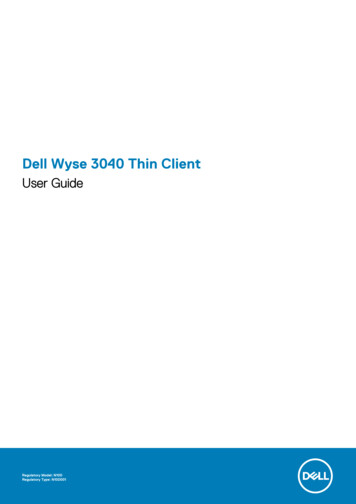
1Product featuresStandard featuresThank you for purchasing an HP thin client. We hope you have years of use from our HP t610 SeriesFlexible Thin Clients. Our goal is to provide you with award-winning clients that are easy to deploy andmanage with the power and reliability you expect.The next sections describe the features of the thin clients. For a complete list of the hardware andsoftware installed on a specific model, visit 4-12454-321959-338927-89307.html and search for a specific thin client model.The thin clients exhibit the following features: no diskette drives 5-minute setup time central deployment and management using a broad range of easy and scalable remotemanagement solutionsVarious options are available for your thin client. For more information about available options, visit theHP website at 4-12454-321959.html.Front panel componentsFigure 1-1 HP t610 Thin Client (left) and HP t610 PLUS Thin Client (right) front panel components(1)Power button(4)Line-out (headphone) audio connector(2)Flash activity LED(5)Universal serial bus (USB) connectors (2)Standard features1
(3)Line-in (microphone) connectorFor more information, refer to the model-specific QuickSpecs at kSpecs Archives/QuickSpecs Archives.html.2Chapter 1 Product features
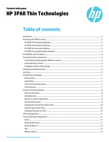
Rear panel componentsFor more information, http://www.hp.com and search for your specific thin client model to find themodel-specific QuickSpecs.Figure 1-2 HP t610 Thin Client rear panel components(1)DVI-I connector for DVI-D and VGA output(6)Serial connector(2)DisplayPort connector(7)PS/2 connectors (2)(3)Ethernet RJ-45 connector(8)Power cord retention slot(4)Universal serial bus (USB) connectors (2) 2.0(9)Cable lock slot(5)Universal serial bus (USB) connectors (2) 3.0(10)Power connectorFigure 1-3 HP t610 PLUS Thin Client rear panel components(1)DVI-I connector for DVI-D and VGA output(7)PS/2 connectors (2)Rear panel components3
(2)DisplayPort connector(8)Power cord retention slot(3)Ethernet RJ-45 connector(9)Cable lock slot(4)Universal serial bus (USB) connectors (2) 2.0(10)Parallel connector(5)Universal serial bus (USB) connectors (2) 3.0(11)PCI-Express expansion slot(6)Serial connector(12)Power connectorInstalling the rubber feetCAUTION: To prevent loss of performance or damage to the thin client, be sure to install the rubberfeet before operating the thin client in a horizontal orientation.To install the rubber feet:1.As you face the front of the thin client, lay the thin client on its left side.2.Remove the feet from their backing.3.Press each foot down securely onto a corner of the right side of the thin client.Figure 1-4 Installing the rubber feetInstalling the standIf the thin client will be installed in an vertical orientation and it will not be mounted, the stand shouldbe installed for stability.To install the stand:41.Turn unit upside down.2.Locate the slots on the bottom of the unit into which the tabs on the stand fit.Chapter 1 Product features
3.Insert the tabs into the slots, and then slide the stand about 1.26 cm (1/2 inch) toward the front ofthe unit until it locks into place.Figure 1-5 Installing the standRemoving the standTo remove the stand:1.Turn unit upside down.2.Press the tab (1), and then slide the stand about 1.26 cm (1/2 inch) toward the back of the unitand lift the stand off the unit (2).Figure 1-6 Removing the standRemoving the stand5
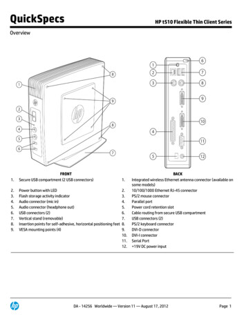
Using the power cord retention slotTo prevent accidental disconnection, press a loop of the power cord into the power cord retention slot.Figure 1-7 Power cord retention slot (HP t610 PLUS Thin Client pictured in horizontal orientation)Using the keyboardFigure 1-8 Keyboard features6(1)Caps Lock keyActivates/deactivates the Caps Lock feature.(2)Scroll Lock keyActivates/deactivates the Scroll Lock feature.(3)Num Lock keyActivates/deactivates the Num Lock feature.(4)Ctrl keyUse in combination with another key; its function depends on theapplication software you are using.(5)Windows Logo Key1Opens the Start menu in Microsoft Windows. Use in combination withother keys to perform other functions. For more information, see Windowslogo key on page 8.Chapter 1 Product features
(6)Alt keyUse in combination with another key; its function depends on theapplication software you are using.(7)Application key1Similar to the right mouse button, opens pop-up menus in a MicrosoftOffice application. May perform other functions in other softwareapplications.(8)Editing keysIncludes the following: Insert, Home, Page Up, Delete, End, and PageDown.Hold Ctrl and Alt while pressing Delete to restart the thin client.1Available in select geographic regions.Using the keyboard7
Windows logo keyUse the Windows Logo Key in combination with other keys to perform certain functions available inWindows operating systems.Windows Logo Key TabSwitch between open items.Windows Logo Key eOpen My Computer.Windows Logo Key fSearch for a file or folder.Windows Logo Key Ctrl fSearch for computers.Windows Logo Key mMinimize all windows.Windows Logo Key Shift mUndo minimize all.Windows Logo Key BreakDisplay the System Properties dialog box.Windows Logo Key rOpen the Run dialog box.Additional function keysThe following key combinations also work on HP thin clients:Alt EscCycles through minimized applications.Alt TabCycles through open applications.Alt Shift TabSwitches to the previous session.Special mouse functionsMost software applications support the use of a mouse. The functions assigned to each mouse buttondepend on the software applications you are using.8Chapter 1 Product features
Serial number locationEvery thin client includes a unique serial number located as shown in the following illustration. Havethis number available when contacting HP customer service for assistance.Figure 1-9 Serial number locationSerial number location9
2Hardware changesGeneral hardware installation sequenceTo ensure the proper installation thin client hardware components:1.Back up any data, if necessary.2.If the thin client is powered on:a.Turn the unit and any other attached devices off.b.Disconnect the power cord from the wall outlet.c.Disconnect any external devices or cables, such as a cable lock.WARNING! To reduce the risk of personal injury from electrical shock and/or hot surfaces, besure to disconnect the power cord from the wall outlet and allow the internal system components tocool before touching.WARNING! To reduce the risk of electrical shock, fire, or damage to the equipment, do notplug telecommunications or telephone connectors into the network interface controller (NIC)receptacles.CAUTION: Static electricity can damage the electronic components of the thin client or optionalequipment. Before beginning these procedures, ensure that you are discharged of static electricityby briefly touching a grounded metal object. See Electrostatic discharge on page 37 for moreinformation.3.Remove the stand, if it is installed. See Removing the stand on page 5 for more information.4.Remove the side access panel and metal side cover, if necessary. See Removing and replacing theside access panel and metal side cover on page 11 for more information.5.Remove any hardware that you will replace.6.Install or replace equipment. For removal and replacement procedures, see the following sections: Removing and replacing the battery on page 14 Installing a SODIMM on page 16 Installing a flash memory module on page 18 Replacing an internal hard drive on page 20 Installing a PCI-Express card on page 23NOTE: Option kits include more detailed installation instructions.7.10Replace the side access panel and metal side cover. See Removing and replacing the side accesspanel and metal side cover on page 11 for more information.Chapter 2 Hardware changes
8.Install the stand, if you will be using the thin client unmounted in a vertical orientation. SeeInstalling the stand on page 4 for more information.9.Reconnect any external devices and power cords.10. Turn on the monitor, the thin client, and any devices you want to test.11. Load any necessary drivers.NOTE: You can download select hardware drivers from HP at http://www.hp.com/country/us/eng/support.html.12. Reconfigure the thin client, if necessary.Removing and replacing the side access panel andmetal side coverRemoving the side access panelWARNING! Before removing the side access panel, ensure that the thin client is turned off and thepower cord is disconnected from the electrical outlet.To remove the left or right access panel:1.Remove the stand, if it is installed. See Removing the stand on page 5 for more information.2.Press the tab on the bottom cover (1), and then slide the cover back (2) and lift it off the chassis.Figure 2-1 Removing the bottom cover3.Lay the thin client on its side on a secure working surface. Remove the right side access panel to remove or install a SODIMM. Remove the left side access panel to: Remove or replace the battery Install or remove a flash memory moduleRemoving and replacing the side access panel and metal side cover11
4. Install or remove an internal hard drive Install or remove a PCI Express cardSlide the access panel about 6.35 mm (1/4 inch) toward the bottom of the unit, and then lift theaccess panel up and off the chassis.Figure 2-2 Removing the side access panelRemoving the left metal side coverNOTE: Do not remove the metal side cover to install a SODIMM. The SODIMM compartment is in theright side of the chassis.You must remove the metal side cover to access internal components such as the battery or to install aflash memory module, internal hard drive, or PCI-Express card.1.Push the tab in the front edge of the side cover toward the back to release the sided cover (1).2.Lift the front edge of the metal side cover (2), then pull the cover to the front and lift it off thechassis (3).Figure 2-3 Removing the metal side cover12Chapter 2 Hardware changes
Replacing the left metal side cover1.Place the metal side cover on the chassis, rear edge first, making sure to insert the two tabs of therear edge into the notches in the chassis (1).2.Align the tabs on both sides of the cover and press the front edge down firmly until the latchcloses.Figure 2-4 Replacing the metal side coverReplacing the side access panelTo replace the access panel:1.Place the access panel on the side of the unit, offset about 6.35 mm (1/4 inch) toward the top ofthe unit (1), allowing the hooks on the underside of the panel to slip into notches in the side accesspanel.2.Slide the panel toward the bottom of the unit until it locks into place (2).Figure 2-5 Replacing the side access panelRemoving and replacing the side access panel and metal side cover13
3.Turn the chassis upside down. Align the hooks on the underside of the bottom cover with the slotsin the chassis and press the cover down and then forward until it locks in place.Figure 2-6 Replacing the bottom cover4.Replace the stand, if the thin client is to be used in the tower orientation.Removing and replacing the batteryBefore beginning the replacement process, review General hardware installation sequence on page 10for procedures you should follow before and after installing or replacing hardware.WARNING! You must remove the left side panel to access the battery. Before removing the sideaccess panel, ensure that the thin client is turned off and the power cord is disconnected from theelectrical outlet.To remove and replace the battery:1.14Locate the battery on the system board.Chapter 2 Hardware changes
2.To remove the battery, pull the metal clamp extending above the battery aside and lift the batteryout (1).Figure 2-7 Removing and replacing the internal battery3.To insert the replacement battery, position it with the positive side facing the chassis wall. Slide thebattery down into the slot until the clamp snaps over the edge of the battery (2).HP encourages customers to recycle used electronic hardware, HP original print cartridges, andrechargeable batteries. For more information about recycling programs, go to www.hp.com/recycle.Batteries, battery packs, and accumulators should not be disposed of together with the general householdwaste. In order to forward them to recycling or proper disposal, please use the public collection system orreturn them to HP, an authorized HP partner, or their agents.The Taiwan EPA requires dry battery manufacturing or importing firms, in accordance with Article 15 orthe Waste Disposal Act, to indicate the recovery marks on the batteries used in sales, giveaways, orpromotions. Contact a qualified Taiwanese recycler for proper battery disposal.Installing thin client optionsVarious options can be installed on the thin client: Installing a SODIMM on page 16 Installing a flash memory module on page 18 Replacing an internal hard drive on page 20 Installing a PCI-Express card on page 23 Installing external drives on page 25Installing thin client options15
Installing a SODIMMThe computer comes with double data rate 3 synchronous dynamic random access memory (DDR3SDRAM) small outline dual inline memory modules (SODIMMs).The memory sockets on the system board can be populated with up to two industry-standardSODIMMs. These memory sockets are populated with at least one preinstalled SODIMM. To achievethe maximum memory support, you can populate the system board with up to 4 GB of memory.For proper system operation, the SODIMMs must be: industry-standard 204-pin unbuffered non-ECC PC3-12800 DDR3-1600 MHz-compliant 1.5 volt DDR3-SDRAM SODIMMsThe DDR3-SDRAM SODIMMs must also: support CAS latency 9 DDR3 1600 MHz (9-9-9 timing) contain the mandatory Joint Electronic Device Engineering Council (JEDEC) specificationIn addition, the computer supports: 2-Gbit non-ECC memory technologies single-sided and double-sided SODIMMS SODIMMs constructed with x8 and x16 devices; SODIMMs constructed with x4 SDRAM are notsupportedNOTE: The system will not operate properly if you install unsupported SODIMMs.Before beginning the replacement process, review General hardware installation sequence on page 10for procedures you should follow before and after installing or replacing hardware.WARNING! You must remove the right side panel to access the SODIMM compartment. Beforeremoving the side access panel, ensure that the thin client is turned off and the power cord isdisconnected from the electrical outlet.CAUTION: You must disconnect the power cord and wait approximately 30 seconds for the powerto drain before adding or removing memory modules. Regardless of the power-on state, voltage isalways supplied to the memory modules as long as the computer is plugged into an active AC outlet.Adding or removing memory modules while voltage is present may cause irreparable damage to thememory modules or system board.The memory module sockets have gold-plated metal contacts. When upgrading the memory, it isimportant to use memory modules with gold-plated metal contacts to prevent corrosion and/oroxidation resulting from having incompatible metals in contact with each other.Static electricity can damage the electronic components of the computer or optional cards. Beforebeginning these procedures, ensure that you are discharged of static electricity by briefly touching agrounded metal object. For more information, refer to Electrostatic discharge on page 37.When handling a memory module, be careful not to touch any of the contacts. Doing so may damagethe module.To install the SODIMM:16Chapter 2 Hardware changes
NOTE: Populate the SODIMM sockets in the following order: SODIMM1, then SODIMM2.1.Slide the serial number tab out of the way.NOTE: Be sure not to lose this tab.2.Pull the front of the access plate up, and lift it off the thin client.Figure 2-8 Removing the SODIMM access plate3.Align the notched edge of the SODIMM with the tab in the socket.CAUTION: To prevent damage to the SODIMM, hold it by the edges only. Do not touch thecomponents on the SODIMM, and do not bend the SODIMM.4.Hold the SODIMM at approximately a 20-degree angle, and then press the SODIMM into thesocket (1) until it is seated. Gently apply pressure to both the left and right edges of the SODIMMuntil the retention clips snap into place.NOTE: A SODIMM can be installed in only one way. Match the notch on the SODIMM with thetab on the socket.Figure 2-9 Installing a SODIMMInstalling thin client options17
5.Press the SODIMM down into the compartment (2).6.If you are installing the SODIMM in the HP t610 Thin Client, place a thermal pad on theSODIMM.CAUTION: The thermal pad is required to help cool the SODIMM in the HP t610 Thin Client.(The HP t610 PLUS Thin Client does not require a thermal pad.)Figure 2-10 Installing the thermal pad in the HP t610 Thin Client7.Insert the tab on the front edge of the access plate into its slot (1) and press the plate down lightlyto engage the latch (2).Figure 2-11 Replacing the SODIMM access plate8.Slide the serial number tab back to its original position.Installing a flash memory moduleBefore beginning the installation process, review General hardware installation sequence on page 10for procedures you should follow before and after installing or replacing hardware.18Chapter 2 Hardware changes
WARNING! You must remove the left side panel to access the system board. Before removing theside access panel, ensure that the thin client is turned off and the power cord is disconnected from theelectrical outlet.CAUTION: Static electricity can damage the electronic components of the computer or optionalcards. Before beginning these procedures, ensure that you are discharged of static electricity by brieflytouching a grounded metal object. When handling a memory module, be careful not to touch any ofthe contacts. Doing so may damage the module.To install the flash memory module:1.If an internal hard drive is installed, remove it. See Removing an internal hard drive on page 21for instructions.2.Locate the correct flash memory module socket on the system board.a.The PATA socket (1) is populated by default.b.The SATA socket (2) can be populated with an optional SATA flash memory module.Figure 2-12 Identifying the Flash Memory Module socketsInstalling thin client options19
3.Align the connector on the flash memory module with the socket on the system board and pressthe flash memory module into the socket.NOTE: A flash memory module can be installed in only one way. Line up the hole in the flashmemory module with the retention post on the system board.Figure 2-13 Inserting the flash memory module4.Press the module connectors firmly into the flash memory module socket (1), making sure that theretention post on the system board is aligned with the hole in the module.Figure 2-14 Securing the flash memory module5.Insert the screw provided in the flash memory module option kit through the hole in the moduleinto the retention post (2) and tighten to secure the module.Replacing an internal hard driveBefore beginning the replacement process, review General hardware installation sequence on page 10for procedures you should follow before and after installing or replacing hardware.20Chapter 2 Hardware changes
WARNING! You must remove the left side panel to access the system board. Before removing theside access panel, ensure that the thin client is turned off and the power cord is disconnected from theelectrical outlet.Removing an internal hard driveTo remove an internal hard drive:1.If a PCI-Express card is installed, remove it.2.Lift the drive bracket latch (1) and slide the drive bracket out of the retention bracket (2).Figure 2-15 Removing the hard drive bracket from the retention assembly3.Remove the four screws that secure the hard drive in the drive bracket (1) and remove the harddrive from the bracket (2).Figure 2-16 Removing the hard drive from the drive bracketNOTE: Keep the four screws to use to install another hard drive.Installing thin client options21
Installing an internal hard driveTo install an internal hard drive:1.If a PCIe card is installed, remove it.2.Insert the hard drive into the drive bracket (1) and secure it by fastening the four screws providedin the kit (2).Figure 2-17 Inserting the hard drive into the drive bracket3.Locate the internal hard drive connector (1) and retention bracket (2) on the system board.Figure 2-18 Locating the hard drive connector and retention bracket on the system board22Chapter 2 Hardware changes
4.Align the screws on the side of the drive bracket with the slots inside the retention bracket andslide the drive bracket into the retention bracket (1).Figure 2-19 Securing the hard drive in the drive bracket5.Press the drive bracket latch down firmly to push the drive onto the internal hard drive connectorand secure the drive assembly (2).6.Reinstall the PCIe card, if necessary. See Installing a PCI-Express card on page 23 forinstructions.Installing a PCI-Express cardYou may install an optional PCI-Express (PCIe) card in the HP t610 PLUS Thin Client, which has a PCIeriser card installed.Before beginning the replacement process, review General hardware installation sequence on page 10for procedures you should follow before and after installing or replacing hardware.WARNING! You must remove the left side panel to access the system board. Before removing theside access panel, ensure that the thin client is turned off and the power cord is disconnected from theelectrical outlet.Installing thin client options23
To install a PCIe card:1.Press down on the plastic blank tab and pull it out of the chassis.Figure 2-20 Removing the expansion slot blank2.Open the metal latch securing the expansion slot cover on the inside of the thin client (1) andremove the expansion slot cover (2).Figure 2-21 Removing the expansion slot coverCAUTION: Do not lose this expansion slot cover. If you remove an expansion card, you mustreplace it with a new card or expansion slot cover for proper cooling of internal componentsduring operation.24Chapter 2 Hardware changes
3.Align the PCIe card connector with the PCI riser card socket and the expansion slot. Press the PCIecard firmly into the socket to ensure that the PCIe card is seated correctly and that the connectorfits the expansion slot properly (1).Figure 2-22 Installing the PCIe card4.Close the metal latch to secure the PCIe card (2).Installing external drivesVarious external USB drives are available as options for the t610 Series Thin Clients. For moreinformation about these drives, visit 4-12454-321959.html, or refer to the instructions that accompany the option.For more information about available options, visit the HP website at 4-12
feet before operating the thin client in a horizontal orientation. To install the rubber feet: 1. As you face the front of the thin client, lay the thin client on its left side. 2. Remove the feet from their backing. 3. Press each foot down securely onto a corner of the right side of the thin client. Figure 1-4 Installing the rubber feet .