Transcription
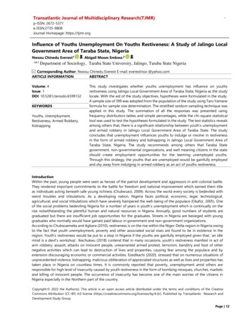
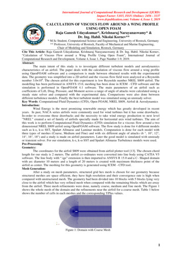
The development of flexible integrated circuits based on thin-film transistorsKris MynyImec, Leuven, Belgiume-mail: kris.myny@imec.beAbstractThe use of thin-film transistors in liquid crystal display applications was commercialized about30 years ago. The key advantages of thin-film transistor technologies compared withtraditional silicon CMOS (complementary metal-oxide-semiconductor) transistors are theirability to be manufactured on large substrates at a low-cost per unit area and at low processingtemperatures, which allows the transistors to be directly integrated onto a variety of flexiblesubstrates. Here, I discuss the potential of thin-film transistor technologies in the developmentof low-cost, flexible integrated circuits for applications beyond flat-panel displays, includingthe Internet-of-Things and lightweight wearable electronics. Focusing on the relatively maturethin-film transistor technologies that are available in semiconductor fabrication plants today,the different technologies are evaluated in terms of their potential circuit applications and theimplications they will have in the design of integrated circuits, from basic logic gates to morecomplex digital and analogue systems. I also discuss microprocessors and non-silicon, nearfield communication (NFC) tags that can communicate to smartphones, and I propose theconcept of a Moore’s law for flexible electronics.*****Thin-film transistors (TFTs) are currently the dominant technology for in-pixel switches anddrivers in flat-panel displays. Trends in consumer electronics demand ever higher displayresolution and brightness, lower power consumption, and new features and form factors(such as curved and foldable displays). This drives TFT devices to deliver more complexfunctions than simply switching. For example, recent bezel-less displays delegate the selectionof rows to be programmed to TFT circuits integrated next to the pixel array. Such drivercircuits comprise thousands of switches operating together. This was previously a job forsilicon chips mounted around the display.Beyond displays, how far can thin-film circuits go in terms of replacing silicon CMOS chips?Fig. 1 illustrates the key advantages of thin-film circuits on flexible substrates. The circuits canbe fabricated on large substrates, creating very thin, light-weight and ultra-flexibleelectronics1,2. Folding, rolling or crumpling the flexible circuits is possible without destroyingthe electronic functionality. Because of these properties, a flexible TFT-basedmicroprocessor3 (Fig. 1d) or a thin-film near field communication (NFC) tag (Fig. 1e) can, forexample, be integrated imperceptibly into any object. Thin-film transistor technologies alsohave considerable potential for fabrication on ultrathin, stretchable substrates4, which can bemade porous creating breathable devices for contact to skin. With these features, thin-filmintegrated circuits (ICs) could be a gamechanger for wearable electronics. Ultra-thin,conformable ICs in the form of a tattoo, could be used to monitor vital body parameters,communicating these parameters directly to a patient’s smartphone or to a medical doctor’sdatabase.
In this Perspective, I discuss the potential of thin-film circuits on plastic substrates for thedevelopment of Internet-of-Things (IoT) and wearable applications. I first look at the differentTFT technologies that can be realized on flexible substrates, and then discuss the impact TFTtechnology will have on circuit design at the level of digital logic gates and VLSI (very-largescale integration) digital circuits. For VLSI digital circuits, I consider the use of thin-film ICs inthe creation of low-cost radio-frequency identification (RFID) tags for everyday items. Initiallyflexible chips may be used to simply identify each item. In a next step, when the RFID chip ispotentially replaced with a thin-film near-field communication (NFC) chip, standardsmartphones and tablets equipped with NFC readers could identify the objects and connectthem to the cloud. Another advantage of thin-film IC technology is the possibility of beingcombined with sensor or signage technology, therefore integrating more functionality into theobjects, and this is discussed in a section on analogue circuits. Finally, I will briefly examinethe potential of silicon CMOS chip technology directly interfaced with TFT circuitry.Thin-film transistor technologyThe development and optimization of transistor technologies are driven by four importantfigures-of-merit: area, cost, power and performance. Power and performance are applicationspecific parameters, which tend to become more demanding as the application field evolves.As thin-film transistors are mainly developed for display-like applications, the drivers oftechnological evolution are the demand for higher resolution and brightness, which pushestransistors to increased density and semiconductor performance. This evolution is alsobeneficial for thin-film IC applications.Thin-film transistor technologies have the potential to be low cost, due to the simple processflow (i.e. limited number of lithographical steps compared to Si CMOS) and material choices.Typical channel lengths for TFT technologies are in the µm range. Currently, thin-filmintegrated circuits are area-inefficient due to non-optimized design flows including the factthat transistor architectures have not been optimized for integrated circuits. As an example,a digital standard cell based CMOS IC comprises several metal layers dedicated to routing,which are on top of the Si CMOS transistor layers. Standard TFT transistor architectures onthe other hand have a limited number of metal layers available (Fig. 1f), as it is not requiredfor backplane applications. Interconnecting different standard cells for a TFT-based digital chipcan only be realized by the metal layers already present in the TFT stack. Routing on top ofsuch standard cells cannot be maximized resulting in a non-optimal area consumption of TFTbased digital chips.At present, the mainstream thin-film transistor technologies, which are available in consumerelectronics products, are amorphous silicon (a:Si), low-temperature polycrystalline silicon(LTPS) and amorphous metal-oxide semiconductors (mainly Indium-Gallium-Zinc-Oxide orIGZO) (Table 1). Metal-oxide TFT is a promising n-type only technology for flexible ICcircuits, as it can be manufactured at process temperatures within thermal budget of flexiblesubstrates5, while still exhibiting a charge carrier mobility close to or above 10cm²/Vs, incontrast to 0.5-1cm²/Vs for a-Si6,7. LTPS transistors require larger process temperatures anda more complex process flow, resulting in complementary p-type and n-type TFTs with largermobilities (50-100cm²/Vs)7,8. In addition, the amorphous nature of IGZO as a semiconductor5enables a TFT scaling roadmap, whereby shorter channel TFTs retain good performancecharacteristics, which is beneficial for both high resolution displays and flexible IC applications.In contrast, polycrystalline semiconductors have a negative impact on TFT behaviour
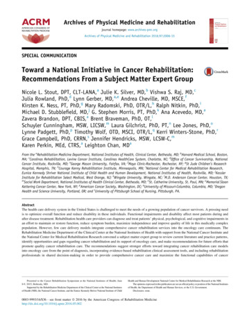
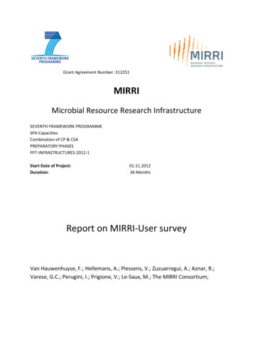
depending on crystal size and channel lengths. Short channel IGZO TFTs down to 30nm havebeen demonstrated already, for transistors fabricated in the back-end-of-line of a conventionalsilicon CMOS chip technology9. Moreover, organic transistors are widely studied as apotential candidate for flexible ICs to complement n-type metal-oxide TFTs10, because p-typemetal-oxides matching the performance of amorphous IGZO have not been discovered.A recent review on the effects of mechanical stress on the intrinsic electrical performance ofdifferent semiconductors concluded that amorphous metal-oxide semiconductors are themost resilient under mechanical strain11. In addition, semiconductors are patterned mostlyinto small islands and the critical layers of the thin-film transistor stack can be located nearthe neutral plane of the full stack by matching the substrate and the topstrate or encapsulation.This is fully exemplified by the ultra-flexible organic TFT backplane, which measures a totalthickness of only 2µm1.This article focuses on the mature technologies that are available in semiconductor fabricationplants (or fabs) today, Nevertheless, it is worth noting that recent developments with carbonnanotubes12–15 and several two-dimensional semiconductors16, such as graphene15,17,18, blackphosphorus19 and chalcogenides20–23, are encouraging and these materials could provide nextgeneration flexible TFT IC technologies, as a novel standalone transistor technology or bycomplementing existing TFTs. It also worth noting that a key benefit of some TFT technologiesis the possibility to use additive manufacturing techniques like printing, which could reducecosts24–29. The main challenges of printed electronics at a circuit level are variability (devicemismatch), large overlaps (source-drain to gate) due to layer-to-layer registration rulesincreasing the parasitics, and large device dimensions, which result in slower operating circuits.Digital logic gatesLogic gates are the building blocks for complex digital circuits and require specific optimizationdepending on the process technology. The most optimal configuration is CMOS, profitingfrom the co-existence of complementary p-type and n-type transistors and all the circuittechniques developed for conventional Si CMOS since the 1970s. In LTPS complementarylogic is possible, but organic and metal-oxide TFTs do not have adequate complementarycounterparts. The level of matching of both transistor-types will affect the properties of thecomplementary logic gate, including speed, power, robustness and area. In a complementarytechnology, both transistor types need to possess a near-zero threshold voltage andsufficiently low off-current. Furthermore, the charge carrier mobilities must differ by no morethan a decade. The low threshold voltages are necessary and key to downscaling the supplyvoltage. Off-currents impact directly the static leakage current of the logic gate in the on- oroff-state and therefore total power consumption. Fig. 2 shows an example whereby the offcurrent of the p-type transistor contributes mainly to the static power consumption fordifferent integration levels of the targeted circuit. Low off-currents will become moreimportant for higher circuit integration densities. In addition, differences in charge carriermobilities between the n-type and p-type TFTs have an impact on area, speed and power. Ifthe mobilities differ too much, the area consumption and speed of the complementary logicgate will be negatively affected in favour of unipolar logic gates.A complementary technology flow is more complex compared to the fabrication of a unipolartransistor technology, and the additional steps for a complementary flow relate directly to anincreased manufacturing cost. Therefore, from the cost perspective, unipolar technologies
can be beneficial for the realization of the flexible digital IC, especially when there is no areareduction as a result of the introduction of a non-matching complementary semiconductor.Unipolar logic gates are the main option to realize flexible ICs for the TFT technologies thatdo not have a complementary counterpart. The main disadvantages of unipolar logic gateswith respect to complementary logic gates are a reduced robustness30, and an increased areaand power consumption. Fig. 2 details different unipolar logic topologies. Resistive-load logicrequires on-chip resistors, and will result in the lowest TFT-count. If the technology does notoffer resistors in the right range, alternatively a TFT can be used as a load. Two options areshown in Fig. 2e-f: enhancement-load or diode-load logic and depletion-load or zero-VGS-loadlogic. Selection of those depend on the available threshold voltage of the existing technology.Zero-VGS-load logic only operates with normally-on devices, or devices which are alreadyswitched on at 0V gate bias. Diode-load logic is operating much faster compared to zero-VGSload logic, but suffers from a low gain and reduced noise margin and therefore robustness31.Several methods can be used to increase the robustness of these logic gates. One option isto increase the number of transistors per logic gate in order to improve the noise margin atthe cost of area. Alternatively, transistors can be operated in two different operation modes– depletion and enhancement – or at least with two different threshold voltages per logicgate. A practical implementation of different threshold voltages can be rooted in thetechnology, by, for example, doping the channel, by varying the thickness of thesemiconductor, or by varying the gate-dielectric thickness. A consideration in the choice ofthe implementation is that the process flow should stay sufficiently simple that yield and costremain attractive.By nature of having a thin film of semiconductor as the active layer, a thin-film transistor cannaturally be equipped with two gates: the front-gate and back-gate. A back-gate operates in asimilar way as the body bias of Si CMOS and can be used to regulate the threshold voltage ofeach TFT individually. Dual-gate unipolar inverters have proven already their benefits in termsof logic gate robustness32 without an additional penalty on area. In this solution, a global, chiplevel bias signal to shift the VT of, for example, all drive TFT is required. The inverter schemeis shown in Fig. 2g.The logic gate robustness can also be improved for back-gate-free TFT technologies byintroducing more transistors per logic gate. Two examples are level shifters33 and PseudoCMOS logic (Fig. 2h)34. Both options allow to shift the voltage transfer curve of the invertertowards the middle of the power rail, improving the robustness. Besides an increase inconsumed area, an additional power rail to drive the additional TFTs may be required foroptimal operation. Positive feedback level shifter logic employs 4 to 5 TFTs for an inverterfunction with only 2 power supplies35. This logic style results in the largest unipolar invertergain and therefore noise margin per supply voltage published to date (76dB and 8.2V on 20Vrespectively), which is obtained by positive feedback on the backgate, including a global signalwithin power rails to tune individual threshold voltages. Finally, robustness of unipolar logiccan be improved by using unipolar differential logic at the cost of larger area consumption36.Latter logic style uses only unipolar single gate TFTs and combines positive feedback to theconcept of differential logic.A fundamental problem for unipolar logic gates is the static power consumption. Dynamiclogic is therefore an interesting direction as it has already been proven to lower the staticleakage current and improve the area usage37. The leakage current of the technology has an
impact on the operating frequency. VLSI TFT circuits based on such clocked dynamic logic isstill a challenge because of the more difficult design and strong requirements on clocksynchronization.Future trends may be to invent novel logic gates, based on unipolar technologies that activelycompensate for shortcomings of regular unipolar logic gates, without the necessity to add itscomplementary counterpart and consequently a more complex process flow. Such logic gatesmay employ additional transistors with feedback function to reduce the leakage of thetransistors after the switching action has occurred38. Feedback circuits on system level todisable large idle blocks are also unexplored for TFT circuits.A third direction to lower the power consumption can be sought in technologicalimprovements or even evolutions. Technology scaling similar to Moore’s law for flexible thinfilm ICs may also be crucial for the realization of complex VLSI circuits on foil, paving the wayto a larger portfolio of applications. The intrinsic delay of scaled logic gates will improve withthe scaling factor when full scaling (equal in voltage and geometry) is applied (Fig. 2c). Thedensity per function improves with the square value of the scaling factor, so does the powerper function. The power density remains therefore equal. The NFC chip described in the nextsection is comprised of 1712 metal-oxide n-TFTs, exhibiting 7.37ns gate delays and a 7.5mWpower consumption. Fig. 2c recalculates this for 10,000 TFTs, assuming mainly static powerlosses. Applying Moore’s law on flex towards a 200nm gate length results in 438µW powerconsumption for 10000 n-TFTs and 737ps gate delay. These numbers only consider theadvancements of the device parameters. In reality, parasitics from the interconnects play acrucial role and need to be taken into account. Lowly-resistive and strongly decoupled metalwires for interconnects are also of high importance to realize this roadmap. Power densitywill be of huge importance in future, as circuits tend to evolve into more complex chipsyielding more functionality and transistors at a similar area. Power consumption and Jouleheating will require particular attention in thin-film technologies because plastic substratesand thin-film metals are poor heat conductors. If dynamic power consumption in those novellogic styles proves to be dominant, additional voltage scaling and clock frequency reductions(parallelism, pipelining) may contribute to lower the overall power consumption. Other wellknown techniques as optimal device sizing, clock gating and utilization of different logic stylesin one chip (fast logic gates versus low power logic gates) can be elaborated for VLSI flex ICs.TFT technologies are expected to further improve parameters such as charge carriermobilities, variability and bias instabilities. Larger mobilities will enable logic gate optimizationsin terms of speed, area or a combination of both. With LTPS and amorphous oxide TFTs thestate of the art transistor has a self-aligned architecture with minimum parasitic overlapbetween gate and source/drain8,39–41, leading to fast logic gates with small power consumption.Fig. 2c shows such power and delay improvement for slower etch stopper layer (ESL) andfaster self-aligned (SAL) metal-oxide TFT technologies. Fig. 1f details the cross-section of bothTFT architectures. ESL transistors exhibit a large parasitic gate-source and gate-drain overlapcapacitor, which is substantially minimized for the SAL architecture. In addition, the channellength of the SAL technology is equal to the definition of the gate layer which makes it easilyscalable, while on the other hand the channel length of the ESL technology is approximatelythree times its critical dimension due to all necessary overlaps by including the channelprotection layer. More evolutions in stack definition are envisioned to provide moremetallization layers for interconnects and for downscaling the transistor footprint.
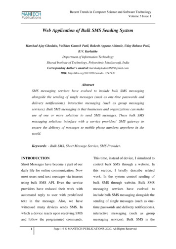
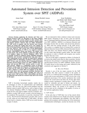
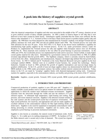
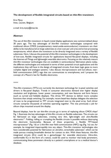
Towards VLSI (digital) circuits on foilRadio-frequency identification tags have received a lot of attention in the field of thin-filmelectronics as they could act as low-cost IoT nodes or tag everyday objects. High-frequencyRFID tags, operating at 13.56MHz base carrier frequency, operate at maximum distances of10cm for proximity readers and up to distance of 1m for vicinity readers. TFT-based RFIDtags can be grouped into two categories: tags that communicate to custom-built RFID readerswith own defined protocols, like 8-bit, 12-bit or 16-bit tags41–45; and tags that communicate tocommercial NFC readers, embedded in many smartphones and handheld devices. The chipdesign requirements are less stringent for the first category, as protocols can be defined withreduced complexity to account for the technology limitations of TFTs. Small-sized dedicatedchips are targeted with limited number of transistors ( 1000) embedding easy protocols,which is less interesting for Si CMOS technologies.NFC tags need to comply with ISO standards (e.g. ISO 14443-A), set for Si CMOStechnologies exhibiting approximately 100x larger charge carrier mobility values compared tometal-oxide TFTs. The selected ISO standard is the NFC Barcode protocol, a tag-talks-onlyprotocol whereby the tag transmits its 128bit memory during 1.21ms and remains silent for3.6ms. This fast NFC protocol can detect a tag within 5ms. The three main challenges todesign a metal-oxide TFT-based NFC Barcode tag are the data rates of 106kbit/s (or carrierfrequency divided by 128), a 128bit memory read out including 16 CRC bits and a limitedincident power at the tag from the smartphone in the range of 10mW. The technology forthis work is a self-aligned metal-oxide TFT architecture, which was selected because of thestrongly reduced parasitics and possibility to downscale the channel length to 2µm and 1.5µm(see Fig. 1f). Pseudo-CMOS logic gates have been chosen to serve as logic family maintainingthe robustness of the chip without the presence of a backgate. Different implementations ofthe pseudo-CMOS logic gate have been used across the design serving different purposes,namely fast implementations for the clock division part and low power implementations forthe core part.Fig. 3 depicts the effect of channel length downscaling. The gate delay of a pseudo-CMOSinverter at 5V VDD and 10V VBIAS improves from 63.4ns to 5.2ns for 5µm to 2µm channellengths. This is within the spec of 7.37ns, determined as maximum gate delay to directly dividethe 13.56MHz incoming clock signal. A fast pseudo-CMOS implementation with 1.5µmchannel length (L1.5F) results in a gate delay of 2.4ns at 5V VDD and 10V VBIAS.These gate delays are sufficient to divide 13.56MHz carrier frequency, however, the powerfigure of these gates suggests a limited use of these gates in the design of the full chip.Therefore, four different ratios yielding low power pseudo-CMOS implementations have beenevaluated, resulting indeed in a lower power operation with a small hit in gate delay (Fig. 3cd), which is affordable for the core part of the chip. Another key advantage of the low powerimplementations, especially LP3 and LP4 is the more symmetric power distribution betweenVDD and VBIAS (Fig. 3g). This will ensure the correct generation of VDD and VBIAS by therectifier circuit, as both power nodes observe a similar load.Low power optimizations at system and architectural level have been performed by selectivelychoosing the proper pseudo-CMOS implementation where needed. The clock generator is a7-stage toggle-flipflop chain, whereby the first stage is implemented with L1.5F logic (Fig. 4b).The power consumption has been decreased gradually along these 7 stages by selecting slowerand power friendly pseudo-CMOS gates. The final stages are implemented with LP3 at channellength 4µm. Latter flavour has been also used for the digital core part (Fig. 4c). The data
formatting block requires slightly faster operating, therefore LP3 at channel length 2µm hasbeen selected. The CRC code has been hardwired or preprogrammed in the memory sincea regular CRC generator would add up to 1/3 of the total number of TFTs. This results in asubstantial reduction of the static power consumption. The memory has been realized in twogenerations, the first generation is just synthesized ROM memory, the second generation islaser-programmed ROM (LPROM) memory. In latter design, 16 bits of the payload and 16CRC bits are one-time programmable in the memory.Fig. 4h shows the die picture of the combined clock generator, digital core generator and dataformatting block. The size of the final chip is determined by the geometry of the standard celllibrary and the number of metals used for interconnects, in this work limited to 2, which alsoserve as gate and source/drain layer. An example standard cell is a 2-input NOR gate (Fig. 4d),employing 6 IGZO TFTs and measuring 163x290µm². The die picture of the chip also revealsthe location of the standard cells and the gaps in between the cells for the automatic placeand route algorithm. The efficiency of the routing and therefore downsizing the chip can beenvisioned by introducing more routing layers, as discussed previously. The standard celllibrary consists of 6 cells, including a buffer and a flipflop. As automatic place and routingalgorithms introduce more parasitics, it was decided to manually route the most time criticalblocks, like the clock generator and the data formatting block.The final chip operates successfully at 3V supply and 6V VBIAS, consumes only 7.5mW powerfor 1712 n-TFTs and measures 50.55mm² (Fig. 4e)46. Fig. 1e shows the photograph of theflexible NFC Barcode chip, including rectifier and load modulator, combined to an inductiveantenna. The chip serves also as the bridge connecting the antenna. The preprogrammed 128bit memory on the flexible NFC tag can be successfully tapped wirelessly into an NFC-enabledsmartphone. Fig. 4e-g provides more measurement details and shows the power increase ofthe chip versus the supply voltage. In addition, the measured signals of the IGZO NFC Barcodetag when approached by an NFC reader device are plotted in Fig. 4f-g. At first the correctprotocol behaviour is observed, with a silent period of 3.6ms alternating between 1.21mscode transmission. A more detailed zoom of the first bits in the sequence shows the correctbit representation and bit-timing according to the ISO 14443-A protocol.Another interesting and complex digital circuit is a microprocessor. The first, and until datemost complex, thin-film flexible microprocessor has been published in 20053. It comprises32k-transistors based on flexible complementary LTPS transistors, which has been releasedfrom carrier by means of the SUFLTA process flow47. The first unipolar organicmicroprocessor fabricated directly on flexible substrates exhibited a clock frequency of 40Hzto execute 8-bit operations48. In addition, 1-bit scalable microprocessor architectures havebeen demonstrated based on different emerging foil-compatible semiconductors, namelycarbon nanotubes12 and two-dimensional materials49. Solution-processed n-type metal-oxideshave been combined to an evaporated p-type organic semiconductor resulting in the firsthybrid organic/oxide 8-bit complementary thin-film microprocessor, operating at 2.1kHz10.Extrapolating the speed of the microprocessor by replacing the logic gates withaforementioned fast pseudo-CMOS logic gates may result in above 100k instructions persecond calculation power enabling a broad application window. The power consumption ofthis chip may probably exceed the application specifications, demanding for many techniquesto reduce the power consumption. At system level, disabling idle blocks in the architectureduring operation by power gating, clock gating or active feedback via the backgates can reducepower consumption. It will also be a great asset if complex architectures can be designedspecifically for the application. Gates which are not used should be eliminated50, memory and
bus widths should be sized compliant to the application requirements and overheads of VLSIcircuits should be limited. If sufficiently fast data processing can be brought to foil at low areaand power consumption, a large application field can be envisioned whereby data can alreadybe preprocessed at patch or IoT-node level.Analogue circuitsInternet-of-Things sensor nodes collect data in the analogue domain, to be digitized withanalogue-to-digital or time-to-digital converters prior to cloud storage. Data processing indigital domain is advantageous for TFT-based circuits as digital circuits are more mature thananalogue TFT-circuits. Analogue to digital converters have already been demonstrated in thinfilm transistor technologies, based on a:Si, organic, metal-oxide and LTPS transistors, yieldingup to 8bit conversion at a maximum sampling rate of 300S/s for unipolar IGZO technologies51.Many advancements are still required prior to developing commercial products, which will bea gradual process from 1bit threshold sensing to multibit sensor conversion.The analogue TFT world also benefits from the technological evolutions discussed in previoussection. Introducing higher mobility semiconductors will lead to faster sampling rates and alarger transconductance, assuming other TFT and process parameters remain similar. Theconversion speed can be increased by downscaling the TFT technology, however, the alreadylimited gain of the operational amplifier or comparator is possibly reduced due to a loweroutput resistance for scaled TFTs. Improvements in variability and bias instabilities will leadto lower offset for differential amplifiers leading to an increased accuracy of the conversion.The introduction of a matching complementary TFT is likely to be the most significantdevelopment for analogue electronics, more than for digital flexible ICs, improving conversionrates, strongly enhancing the offset and gain of the amplifiers and downscaling of the consumedarea. Analogue circuits based on unipolar technologies benefit already if stable passives areincluded in the process flow, like a high-resistive layer with low variation, improving the areaand gain of the amplifiers.Amplifiers are required for a multitude of applications, not limited by sensor-node IoT.Integrated sense amplifiers are beneficial to read out different memory topologies in a rapidfashion, from LPROM to SRAM52 and in future non-volatile memory arrays embedded in thinfilm transistor technologies. Large area imaging backplanes require in-pixel amplification andsense amplifiers to detect the incoming signals. Low noise amplification based on TFTtechnologies can also find its way in wearable health patches to monitor vital signals wherebysensors or electrodes are attached to the body and interconnected to a Si CMOS IC. Theanalogue amplifiers can be mounted nearby the sensor/electrode to improve the signal-tonoise ratio of the sensor signal prior to transmission to the Si IC. Single stage high gainamplification in such patches is a strong asset, which has been demonstrated already b
The development of flexible integrated circuits based on thin-film transistors Kris Myny Imec, Leuven, Belgium e-mail: kris.myny@imec.be Abstract The use of thin-film transistors in liquid crystal display applications was commercialized about 30 years ago. The key advantages of thin-film transistor technologies compared with