Transcription
Chapter 11Displaying andAnnotating SectionsAs you have learned, creating a design is only part of the story—youCopyright 2015. John Wiley & Sons, Incorporated. All rights reserved.also have to display and annotate it in ways that effectively represent yourdesign for its intended purpose. This also applies to sections. As you’ll seein this chapter, there are styles that control the appearance of the sectionsthemselves as well as the section views that house them. There are labelsthat attach themselves to the sections and labels that can float in the sectionviews. In fact, the methods you used to stylize and annotate sections andsection views are very similar to those used for profiles and profile views.Of course, there are also differences. For instance, you have to address thestylization and labeling of a corridor section, which you don’t need to do withprofile views. Another difference is that section views typically are created inbulk, so their arrangement and grouping into sheets must also be managed.In this chapter, you’ll learn to: Apply section styles Apply section labels Control corridor section display with code set styles Apply labels with code set styles Apply section view styles Apply section view bands Apply group plot styles Create section view labelsChappell, Eric. AutoCAD Civil 3D 2016 Essentials : Autodesk Official Press, John Wiley & Sons, Incorporated, 2015. ProQuest Ebook etail.action?docID 2052358.Created from osu on 2017-09-25 17:45:32.
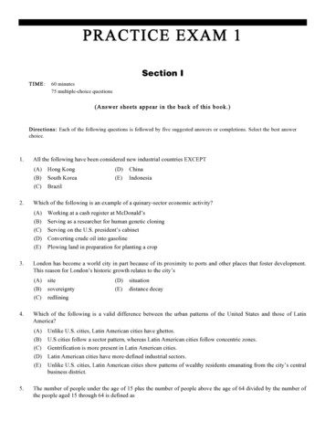
208C h a p t e r 11 D i s p l a y i n g a n d A n n o t a t i n g S e c t i o n sApplying Section StylesCertificationObjectiveCopyright 2015. John Wiley & Sons, Incorporated. All rights reserved.If you haven’t alreadydone so, downloadand install the files forChapter 11 according tothe instructions in thisbook’s Introduction.Before I jump into section styles, I’ll discuss the difference between sectionsand corridor sections. Sections are derived from surfaces, and they can bethought of as a very close relative to surface profiles. Like surface profiles, theyare typically represented by a single line and can be annotated using a label set.Corridor sections are something quite different. You can think of a corridorsection as an assembly superimposed on a section view. It consists of subassemblies, points, links, and shapes. Because of the differences between sections andcorridor sections, the methods you use to stylize and label them are different.With that out of the way, let’s look at section styles. Section styles are used tochange the appearance of a section either directly or by displaying it on a different layer. The most common application of a section style is the differentiationbetween sections that represent existing and proposed ground surfaces. You canalso use section styles to show point markers at each vertex in the section line. Exercise 11.1: Apply Section Styles In this exercise, you’ll apply section styles to differentiate between sections thatrepresent finished ground, existing ground, and rock surfaces.Because you’re working exclusively withsection views in thischapter, the drawingsare set up with a singleviewport rather thanthe multiple viewportsused in prior chapters. You may need to clickthe Section: Rockribbon tab to see theSection Properties icon. Using the SectionProperties command tochange the style is onlyone of three ways youcan do this. You’ll tryout the other two laterin this exercise.1. Open the drawing named Applying Section Styles.dwg located inthe Chapter 11 class data folder.Here, you see three section views that were plotted to investigatethe shallow rock layer. The section views show a corridor section,existing ground surface section, and rock section.2. Click the lowest section in the 8 50.00 (0 260.00) section view, andthen click Section Properties on the Section: Rock ribbon tab.3. On the Information tab of the Section Properties dialog box, changeObject Style to Rock. Click OK to close the dialog box. Press Esc toclear the selection.The rock section now appears as a gray dashed line.4. Repeat the previous two steps for the section that appears above therock layer, this time assigning a style of Existing Ground.The section representing existing ground now appears as a reddashed line along with the rock section from the previous step (seeFigure 11.1).Chappell, Eric. AutoCAD Civil 3D 2016 Essentials : Autodesk Official Press, John Wiley & Sons, Incorporated, 2015. ProQuest Ebook etail.action?docID 2052358.Created from osu on 2017-09-25 17:45:32.
Applying Section Styles209Existing GroundRockF i g u re 1 1 . 1 The sections have been stylized to differentiate between rockand existing ground.5. Click the lower section in the 9 00.00 (0 270.00) section view,right-click, and select Properties.If the section viewgrid obscures the reddashed line, selectthe section view,right-click, and selectDisplay Order BringTo Front. 6. In the Properties window, change Style to Rock. Keep the Propertieswindow open.7. Press Esc to clear the selection of the rock section. Click the existingground section, and use the Properties window to change its style toExisting Ground.Copyright 2015. John Wiley & Sons, Incorporated. All rights reserved.8. Press Esc to clear the previous selection, and then click oneof the grid lines for the 9 25.00 (0 280.00) section view. ClickSection View Properties on the ribbon.9. On the Sections tab of the Section View Properties dialog box, in theStyle column, change the style of the section named EG to ExistingGround, and for the section named Rock, change the style to Rock.Click OK to dismiss the Section View Properties dialog box. Press Escto clear the selection.All three section views should now properly display the existingground and rock sections.10. Save and close the drawing.You can view the results of successfully completing this exercise byopening Applying Section Styles - Complete.dwg.Chappell, Eric. AutoCAD Civil 3D 2016 Essentials : Autodesk Official Press, John Wiley & Sons, Incorporated, 2015. ProQuest Ebook etail.action?docID 2052358.Created from osu on 2017-09-25 17:45:32. Using the Propertieswindow to changethe style is the secondof three methodsavailable to you. Thismethod is a bit quickerbecause both sectionscan be changed in thesame window. Using the Section ViewProperties command tochange the style is thethird of three methodsavailable to you. Thismethod shows all thesections that are present in the section view.
210C h a p t e r 11 D i s p l a y i n g a n d A n n o t a t i n g S e c t i o n sApplying Section LabelsCertificationObjectiveAt times, you may need to annotate sections with information about their elevations, slopes, offsets, and so on. As you learned in Chapter 8, “Displaying andAnnotating Profiles,” label sets enable you to apply multiple labels at once aswell as apply important configuration settings to the labels such as increment,weeding, and so on. For sections, the AutoCAD Civil 3D software environmentprovides the following four types of labels that can be compiled into a label set:Major Offset Labels These labels are placed at constant increments alongthe section. You can use this label type to label offset, elevation, instantaneousgrade, and many other properties.Minor Offset Labels These are the same as major offset labels except they arecreated at a smaller increment and must exist as children of the major offset labels.Segment Labels You use this label type to label the grade, length, and otherproperties of the line segments that make up the section.Copyright 2015. John Wiley & Sons, Incorporated. All rights reserved.Grade Break Labels You use this label type to label the offset, elevation, andother properties of grade breaks—the locations where segments meet.If you haven’t alreadydone so, downloadand install the files forChapter 11 according tothe instructions in thisbook’s Introduction. The first two types are created at increments, so they are spaced evenly acrossthe section. The last two are created at individual components of the section, sothey are placed wherever these components exist. Because sections sometimeshave many short segments, you can configure the label sets to skip points thatare close together to prevent labels from overlapping.Exercise 11.2: Apply Section LabelsIn this exercise, you’ll configure labels to show information on the elevations ofthe rock layer in each section view. Here you see the samethree section viewsfrom the previous exercise. The section viewstyles have been modified to create someextra space beneaththe sections.1. Open the drawing named Applying Section Labels.dwg located inthe Chapter 11 class data folder.2. Click the rock section on the lowest section view, and then click EditSection Labels on the ribbon.Chappell, Eric. AutoCAD Civil 3D 2016 Essentials : Autodesk Official Press, John Wiley & Sons, Incorporated, 2015. ProQuest Ebook etail.action?docID 2052358.Created from osu on 2017-09-25 17:45:32.
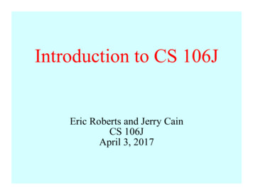
Applying Section Labels2113. In the Section Labels – Rock dialog box, do the following:a. For Type, select Grade Breaks.b. For Section Grade Break Label Style, select Rock.c. Click Add.d. For Dim Anchor Opt, select Graph View Bottom.e. For Dim Anchor Val, enter 0.f. Click OK.You should see three labels along the bottom of the section viewwith lines extending upward from each one.Copyright 2015. John Wiley & Sons, Incorporated. All rights reserved.Anchors AweighIn step 3 of Exercise 11.2, you adjusted two settings relating to anchors. Theconcept of anchors is unique to certain types of labels that appear in sectionviews and profile views. As a label style is composed, certain key points can belocated at an anchor point whose location will be determined at the time thelabel is applied. This gives you some additional control over the placement of thelabels. For example, in the previous steps, you specified that the labels shouldbe aligned to the bottom of the grid by assigning Graph View Bottom as the DimAnchor Opt setting. The Dim Anchor Val setting is an offset from the anchor point,which enables you to fine-tune the position of the label even more. An easy wayto find out whether a label style that you have selected can respond to anchors isto look for a second grip. When initially created, this grip will be located wherethe anchor options specify. The grip can be moved to a location of your choice,providing even more flexibility with label placement.4. Press Esc to clear the selection from the previous step. Click one ofthe labels, and then click Edit Label Group on the ribbon.5. In the Weeding column, change the value to 5 (2). Click OK. PressEsc to clear the selection.Chappell, Eric. AutoCAD Civil 3D 2016 Essentials : Autodesk Official Press, John Wiley & Sons, Incorporated, 2015. ProQuest Ebook etail.action?docID 2052358.Created from osu on 2017-09-25 17:45:32. With the options youhave selected, onlythree labels appear.It would be better toincrease the numberof labels to includemore points along thesection. In steps 4 and5, you’ll adjust theWeeding setting toprovide more labels.
212C h a p t e r 11 D i s p l a y i n g a n d A n n o t a t i n g S e c t i o n sAs shown in Figure 11.2, more labels appear because the Weedingsetting allows the space between the labels to be as small as 5 feet (2meters) rather than 100 feet (25 meters).F i g u re 1 1 . 2 A label set has been applied to the rock section to provideinformation about the elevations of the rock layer.Copyright 2015. John Wiley & Sons, Incorporated. All rights reserved.6. Apply the same labels to the rock section in the other two sectionviews.There Are Label Sets for Section Views TooYou learned about label sets in Chapter 6 and Chapter 8 when dealing with alignment and profile labels. The same label set functionality is available for sectionviews too. Try it for step 6 in Exercise 11.2. Instead of manually setting up therock labels, use the Save Label Set function to save the first configuration, andthen use Import Label Set to apply it to the other section views.7. Save and close the drawing.You can view the results of successfully completing this exercise by openingApplying Section Labels - Complete.dwg.Chappell, Eric. AutoCAD Civil 3D 2016 Essentials : Autodesk Official Press, John Wiley & Sons, Incorporated, 2015. ProQuest Ebook etail.action?docID 2052358.Created from osu on 2017-09-25 17:45:32.
Controlling Corridor Section Display with Code Set St yles213Controlling Corridor Section Display withCode Set StylesYou have already seen how section styles can be used to change the appearanceof sections, but what about corridor sections? As stated earlier, the way this ishandled is different and is done through the use of a code set style. The setup ofcode set styles is complicated, and it’s often left to the expertise of a CAD manager or very experienced Civil 3D user. However, once code set styles are createdand made available to you, the task of assigning them to a corridor section isfairly simple.Code Set StylesCopyright 2015. John Wiley & Sons, Incorporated. All rights reserved.Let’s take a closer look at code set styles. First, it will be easier if you think ofa corridor section as an assembly. You have already learned that assembliesare made up of smaller parts called subassemblies. You have also learned thatsubassemblies are made up of smaller parts called points, links, and shapes.Points, links, and shapes all have at least one code assigned to them, and thislittle string of text is the key to how code set styles work.For example, one code that is used quite often is Pave. The BasicLaneTransitionsubassembly in your corridor uses a rectangular shape to represent the lane,and the Pave code is assigned to this shape as a property of the subassembly.Shapes have styles just like all the other Civil 3D objects you have studied. Forexample, you can create a shape style called Hatched Pavement that displaysthe outline of the shape and fills it with a dot hatch to represent the pavementmaterial. Another shape style might be Basic Pavement, which shows just anoutline and no hatching.Even for a simple assembly, the number of codes that are involved can grow quickly.And the number of styles can grow quickly as well—for example, you may want toapply a different style to each code to visually differentiate pavement from curbingfrom sidewalk, among other things. One job of a code set style is to match up multiplecodes with multiple styles and store them all under one name. So, for example, youmay have a code set style called Basic that uses the Basic Pavement style for anyshape coded Pave. This might be only one of several or even dozens of match-upsbetween style and code in this code set style. Then, in another code set style namedDetailed, you may decide to use the Hatched Pavement style for any instances of thePave shape code. Again, this might be one of many code-style match-ups.(Continues)Chappell, Eric. AutoCAD Civil 3D 2016 Essentials : Autodesk Official Press, John Wiley & Sons, Incorporated, 2015. ProQuest Ebook etail.action?docID 2052358.Created from osu on 2017-09-25 17:45:32.CertificationObjective
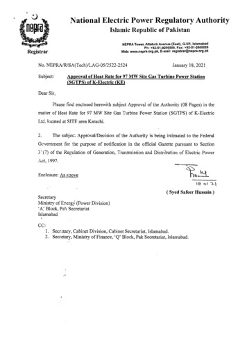
214C h a p t e r 11 D i s p l a y i n g a n d A n n o t a t i n g S e c t i o n sCode Set Styles(Continued)Now, with both code set styles in place, you can quickly change the appearance ofyour corridor section to take on either a Basic or Detailed appearance by simplyswitching the code set style, as shown in the following diagrams.If you haven’t alreadydone so, downloadand install the files forChapter 11 according tothe instructions in thisbook’s Introduction. “Basic” Code Set Style“Detailed” Code Set StyleExercise 11.3: Apply Code Set StylesIn this exercise, you’ll apply different code set styles to corridor sections andobserve the changes that can occur. You’ll explore code set styles for an individual section and for a section view group.Copyright 2015. John Wiley & Sons, Incorporated. All rights reserved. The drawing is zoomedin to the same threesection views from theprevious exercise. The appearance ofthe corridor sectionchanges to a more basicoutline.1. Open the drawing named Applying Code Set Styles.dwg located inthe Chapter 11 class data folder.2. Click the corridor section in the bottom section view, and then clickSection Properties on the ribbon.3. On the Information tab of the Corridor Section Properties dialog box,change Object Style to Road Sections and click OK. Press Esc to clearthe selection.4. Using the same procedure, change the style to Road Sections – TopHighlighted.5. In the lower-right corner of your screen, click the icon for the customization menu. If there is no check mark next to LineWeight, clickLineWeight to activate the button on the status bar. You now see the topsurface of the corridorsection highlightedin red.6. Click the Lineweight icon on the status bar to turn on the display oflineweights.The icon turns blue if the feature is on.Chappell, Eric. AutoCAD Civil 3D 2016 Essentials : Autodesk Official Press, John Wiley & Sons, Incorporated, 2015. ProQuest Ebook etail.action?docID 2052358.Created from osu on 2017-09-25 17:45:32.
Applying Labels with Code Set Styles2157. Change the style of the corridor section to Presentation.With this style, the pavement is hatched with a different patternthan the curbs.8. Press Esc to clear the previous selection. Zoom out, and pan tothe north where the sheets of section views are located. Clickone of the section views, and select View Group Properties on theribbon. This opens the SectionView Group Propertiesdialog box.9. Click the Sections tab. In the Style column, change the style forJordan Court to Presentation.Copyright 2015. John Wiley & Sons, Incorporated. All rights reserved.10. Click OK to dismiss the Section View Group Properties dialog boxand return to the drawing. Zoom in, and study the change to thesection views.The code set style has been assigned throughout the entire sectionview group (see Figure 11.3).F i g u re 1 1 . 3 The Jordan Court corridor section with the Presentation code setstyle applied11. Save and close the drawing.You can view the results of successfully completing this exercise by openingApplying Code Set Styles - Complete.dwg.Applying Labels with Code Set StylesAs you have seen, code set styles are very effective at assigning styles based onpoint, link, and shape codes. They can also be used to apply labels to corridorsections, and just as with styles, codes are the key to automating the placementof labels.Chappell, Eric. AutoCAD Civil 3D 2016 Essentials : Autodesk Official Press, John Wiley & Sons, Incorporated, 2015. ProQuest Ebook etail.action?docID 2052358.Created from osu on 2017-09-25 17:45:32.CertificationObjective
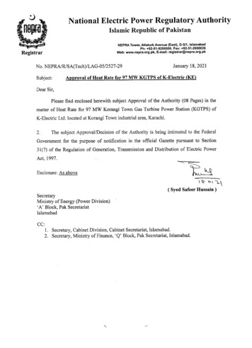
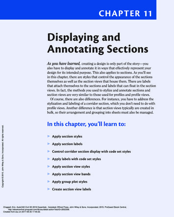
216C h a p t e r 11 D i s p l a y i n g a n d A n n o t a t i n g S e c t i o n s If you haven’t alreadydone so, downloadand install the files forChapter 11 according tothe instructions in thisbook’s Introduction. Once again, the drawing is zoomed in to thedesign section viewsfrom the previousexercises.Exercise 11.4: Apply Labels with Code Set StylesIn this exercise, you’ll use a code set style to add labels to a corridor section.You’ll then modify the code set style to add a label at the crown.1. Open the drawing named Labeling with Code Set Styles.dwglocated in the Chapter 11 class data folder.2. Click the corridor section in the bottom section view, and then selectSection Properties on the ribbon.3. Change Object Style to Design With Labels, and click OK. Press Escto clear the selection.The corridor section now includes labels for slopes, elevations, andshape codes. Next, you’ll modify the code set style to add an elevationlabel at the crown of the road.4. Open the Tool Palettes window by clicking the Tool Palettes icon onthe Home tab of the ribbon. Click the Basic tab in the Tool Paletteswindow to make the Basic palette come to the forefront.You’re taken directly to the Help window for this subassembly.Copyright 2015. John Wiley & Sons, Incorporated. All rights reserved.5. Right-click BasicLaneTransition, and select Help.You’re taken directly to the Help window for this subassembly.Note that point P1 is coded Crown (see Figure 11.4)—this is the codeyou’ll use.F i g u re 1 1 . 4 Coding diagram for the BasicLaneTransition subassemblyChappell, Eric. AutoCAD Civil 3D 2016 Essentials : Autodesk Official Press, John Wiley & Sons, Incorporated, 2015. ProQuest Ebook etail.action?docID 2052358.Created from osu on 2017-09-25 17:45:32.
Applying Section View Styles2176. Scroll to the bottom of the Help page, and study the coding diagram.7. Close the Help window. Click the corridor section, and thenclick Section Properties Edit Code Set Style on the ribbon.8. On the Codes tab of the Code Set Style dialog box, expand the Pointsection and locate the Crown code beneath it.9. Click the icon to the right of None in the Label Style columnacross from Crown. Select Crown Elev, and click OK.Copyright 2015. John Wiley & Sons, Incorporated. All rights reserved.10. Click OK to dismiss the Code Set Style dialog box. Press Esc to clearthe selection of the section.A marker and label are now displayed at the crown of the road. Thecode set style recognized the use of the Crown code in the corridorsection and applied the label accordingly (see Figure 11.5). Normally, editing astyle would be considered outside the scopeof this book; however,this simple exercisewill help you understand the link betweenthe code and the label.F i g u re 1 1 . 5 A code set style that includes labels has been applied to theJordan Court corridor section.11. Save and close the drawing.You can view the results of successfully completing this exercise by openingLabeling with Code Set Styles - Complete.dwg.Applying Section View StylesNow that you have studied the display and annotation of sections, let’s take alook at the appearance of the section view that provides the backdrop for thesections. Once again, there are many similarities between section views andprofile views. Both have the capability to display a grid, both can apply a verticalChappell, Eric. AutoCAD Civil 3D 2016 Essentials : Autodesk Official Press, John Wiley & Sons, Incorporated, 2015. ProQuest Ebook etail.action?docID 2052358.Created from osu on 2017-09-25 17:45:32.CertificationObjective
218C h a p t e r 11 D i s p l a y i n g a n d A n n o t a t i n g S e c t i o n sIf you haven’t alreadydone so, downloadand install the files forChapter 11 according tothe instructions in thisbook’s Introduction. Exercise 11.5: Apply Section View Styles In this exercise, you’ll experiment with changing the section view style for anindividual section view as well as for a group of section views.Once again, you’reviewing the threedesign cross sectionsthat you have beenworking with in previous exercises. Copyright 2015. John Wiley & Sons, Incorporated. All rights reserved.exaggeration, and both can use bands to provide supplemental informationalong the bottom or the top of the view. In fact, the only significant differencebetween profile views and section views is that profile views display stations(read along the alignment) whereas section views display offsets (read perpendicular to the alignment).One way you might usethis section view styleis for close inspectionand detailed editingof the section, becausethe grid lines appearvery frequently and thevertical dimensions ofthe sections are exaggerated even more.1. Open the drawing named Applying Section View Styles.dwglocated in the Chapter 11 class data folder.2. Click the lowest section view, and then click Section View Propertieson the ribbon.3. On the Information tab of the Section View Properties dialog box,change the style to Design 10V Major And Minor – No Padding. ClickOK. Press Esc to clear the selection.All That with One Style?In step 3 of Exercise 11.5, when you changed the section view style from Design5V Major And Minor to Design 10V Major And Minor – No Padding, the followingchanges were made to the section view: The vertical exaggeration changed from 5 to 10, causing the elevationchanges in the sections to be much more dramatic. The elevation grid interval changed to increase the frequency of both themajor grids and minor grids along with their associated labels. The space beneath the sections (padding) was removed. The minor interval of the offset grid lines was increased.This is a classic example of the power of styles. To make these changes manuallywould have taken several minutes to figure out—even for an experienced user.Instead, all you have to do is assign a different style, and all the changes areapplied instantaneously.Chappell, Eric. AutoCAD Civil 3D 2016 Essentials : Autodesk Official Press, John Wiley & Sons, Incorporated, 2015. ProQuest Ebook etail.action?docID 2052358.Created from osu on 2017-09-25 17:45:32.
Applying Section View Styles4. Use the Section View Properties command to change the style toDesign 1V Major And Minor – No Padding.This view is similar to the previous one, but this time there is novertical exaggeration.5. Use the Section View Properties command to change the style toDesign 1V – No Grid.Because this section view style excludes the grid and labels, youmight use it to create illustrations for a report.6. Use the Section View Properties command to change the style toDesign 5V Major Only.This view is similar to the other views immediately above it, exceptthe minor grids aren’t displayed.7. Press Esc to clear the previous selection. Zoom out, and pan north tothe three sheets of section views. Click one of the section views, andselect View Group Properties on the ribbon.This opens the Section View Group Properties dialog box.Copyright 2015. John Wiley & Sons, Incorporated. All rights reserved.8. On the Section Views tab, click in the Style column in the first rowacross from Section View Group – 1.The new section view style applies a vertical exaggeration of 2, sothe section views take up more space top to bottom. In the next step,you’ll rearrange the views on the sheet so they’re easier to read.9. Select Road Section Type 2, and click OK. Click OK again to dismissthe Section View Group Properties dialog box.10. With one of the section views still selected, click Update GroupLayout on the ribbon.The sections are rearranged, and the new layout must include anadditional sheet (an additional two sheets for the metric drawing)to accommodate the extra space that is now taken up by the sectionviews (see Figure 11.6).F i g u re 1 1 . 6 A fourth sheet is created as a result of changing the section viewstyle applied to the section view group.Chappell, Eric. AutoCAD Civil 3D 2016 Essentials : Autodesk Official Press, John Wiley & Sons, Incorporated, 2015. ProQuest Ebook etail.action?docID 2052358.Created from osu on 2017-09-25 17:45:32.219
220C h a p t e r 11 D i s p l a y i n g a n d A n n o t a t i n g S e c t i o n s11. Save and close the drawing.You can view the results of successfully completing this exercise by openingApplying Section View Styles - Complete.dwg.Applying Section View BandsYou may need to display additional information about the sections to accompany what is conveyed by the section view. Bands can be a useful tool for thispurpose, enabling you to display information both graphically and textually.There are two types of section view bands, as described here:Section Data Bands You use this type of band for labeling offset and elevation data at regular increments along the section view.Section Segment Bands You use this type of band to label length and slopeinformation about individual segments. Because the individual labels are created segment by segment, they aren’t evenly spaced across the band as you seein a section data band. Weeding can be applied to improve situations where segments are short and labels overlap.Copyright 2015. John Wiley & Sons, Incorporated. All rights reserved. If you haven’t alreadydone so, downloadand install the files forChapter 11 according tothe instructions in thisbook’s Introduction.Exercise 11.6: Apply Section View BandsIn this exercise, you’ll apply section view bands to an individual section to display information for stations, elevations, and rock depth. You’ll then apply bandsto a group of section views and update the layout of the section views to accountfor the additional space taken up by the bands.1. Open the drawing named Applying Section View Bands.dwglocated in the Chapter 11 class data folder.2. Click the grid of the bottom section view, and select Section ViewProperties on the ribbon.3. On the Bands tab of the Section View Properties dialog box, do thefollowing:a. For Band Type, verify that Section Data is selected.b. Under Select Band Style, verify that Design – EG Elev isselected.c. Click Add.Chappell, Eric. AutoCAD Civil 3D 2016 Essentials : Autodesk Official Press, John Wiley & Sons, Incorporated, 2015. ProQuest Ebook etail.action?docID 2052358.Created from osu on 2017-09-25 17:45:32.
Applying Section View Bandsd. Change the Gap value for the newly added band to 0.e. Scroll right, and select EG in the Section1 column.f. Click OK.The band is added, but there are values with lines through them
208 Chapter 11 Displaying and Annotating Sections Applying Section Styles Before I jump into section styles, I’ll discuss the difference between sections and corridor sections. Sections are derived from surfaces, and they can be