Transcription
Separation Processes:MembranesChE 4M3 Kevin Dunn, .ca/4M3Overall revision number: 308 (October 2014)1
Copyright, sharing, and attribution noticeThis work is licensed under the Creative Commons Attribution-ShareAlike 4.0International License. To view a copy of this license, please /This license allows you:Ito share - copy and redistribute the material in any wayIto adapt - but you must distribute the new result under thesame or similar license to this oneIcommercialize - you are allowed to use this work forcommercial purposesattribution - but you must attribute the work as follows:III“Portions of this work are the copyright of Kevin Dunn”, or“This work is the copyright of Kevin Dunn”(when used without modification)2
We appreciate:Iif you let us know about any errors in the slidesIany suggestions to improve the notesAll of the above can be done by writing tokevin.dunn@mcmaster.caor anonymous messages can be sent to Kevin Dunn athttp://learnche.mcmaster.ca/feedback-questionsIf reporting errors/updates, please quote the current revision number: 3083
Administrative issuesProject topics are posted. There are 3 main topics:1. commercial, large-scale, production of membranesIIIhow are membranes produced?modifications to operate at higher temperature;modifications made to the surface properties to improve itsperformance and reduce fouling.2. separative reactorsIIIIreactor separation combined together and integrated;operation of the unit;use of separative reactor technology at a large scale;economic impacts.3. bioseparations using chromatography and/or ion-exchangeIIIwhat are the challenges in operating these units?how are the resins and adsorbents typically selected?some terms: capacity; selectivity; specificity; regeneration;loading and unloading.Due by 19 November 2014, at 9:304
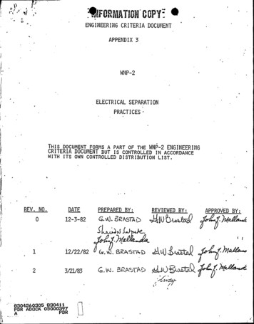
Membranes[Flickr: 21182585@N07/2057883807][Flickr: 21182585@N07/3574729377]5
Quick activityOn a sheet of paper writeIbullet points and/orIdraw a diagram and/orIdescribe“what you know about membranes”6
ReferencesIIIIIIIIPerry’s Chemical Engineers’ Handbook, 8th edition, chapter20.Wankat, “Separation Process Engineering”, 2nd edition,chapter 16.Schweitzer, “Handbook of Separation Techniques forChemical Engineers”, chapter 2.1.Seader, Henley and Roper, “Separation Process Principles”,3rd edition, chapter 14.Richardson and Harker, “Chemical Engineering, Volume 2”,5th edition, chapter 8.Geankoplis, “Transport Processes and Separation ProcessPrinciples”, 4th edition, chapter 7 (theory) and chapter 13.Ghosh, “Principles of Bioseparation Engineering”, chapter 11.Uhlmann’s Encyclopedia, “Membrane Separation Processes, 1.Principles”, DOI:10.1002/14356007.a16 187.pub37
Why use membranes?Some really difficult separations:I finely dispersed solids; density close to liquid phase; gelatinousparticlesI dissolved salts must be removedI non-volatile organics (e.g. humic substances)I biological materials: sensitive to the environmentI biological materials: aseptic operation is requiredIIcannot centrifugecannot sedimentIt is usually worth asking:How does nature separate?I energy efficientI effectiveI maybe slow?8
Why use membranes?Relatively new separation step (“new” meaning since 1960 to 1980s)I often saves energy costs over alternative separationsIIIIambient temperature operationoften easier to operate and controlmore compactlower capital cost than alternativesModules:Ifeed stream split into parallel unitsIeasier to maintain and replace partsIcan be expanded as needs grow[Henk Koops’ slides, GE Water and Process Technologies]9
Challenges in membrane designChallenges that still remain:Iwithstanding high pressure differences but still have a thinmembraneIdealing with fouling and cleaningIincreasing selectivity (separation factor) for specificapplication areasIuniformity of pore sizesItemperature stability (e.g. steam sterilization)Membrane manufacture is a complex area: very fruitful area forpolymer engineers10
Market size[Perry’s: chapter 20, 8ed]11
Let’s formalize some terminology[Seader, Henley and Roper, p 501]12
More terminologysemipermeable: partially permeable, e.g. your skin allows certainsize particles in, but not othersmass separating agent: the membrane itselfenergy separating agent: the applied pressure (pressure drop)porosity area of open porestotal surface area13
What is flux?The (volumetric) or (molar) or (mass) flow per unit time for 1 unit of areaItransfer ratetransfer areae.g. 42 mol.s 1 .m 2I never simplify the units: write 13 m3 .s 1 .m 2Iyou may, and probably should, omit thebrackets: 13 m3 .s 1 .m 2Ido not write 13 m.s 1IJ flux General principleFor a given unit area, we want the highest flux possible (at thelowest possible cost)14
Membrane classification[Richardson and Harker, p 438]15
Transport through a membraneWhy study theoretical models?All forms of membrane applications rely to some extent on thesame equation structure. The details will change.Will allow us to:Itroubleshoot problems with the processIpredict expected impact of improvements/changes to theprocessIused for crudely sizing the unit (order of magnitude estimates)16
Examples you will be able to solve1. how long should we operate unit at constant P to achievedesired separation?2. what is the mass transfer coefficient through the labmembrane?3. what pressure drop (and therefore pump size) do I expect?4. how many cassettes (area) does this application require?17
The general equation(permeability)(driving force)driving forcetransfer rate flux transfer areathicknessresistanceSymbolically:ρfQpρf dV(permeability)(driving force)driving force · J AA dtLRI11permeability “mass transfer coeff”LresistanceRpermeance: easier to measureIpermeance units: depend on choice of (driving force) and JIresistance f (thickness L, viscosity, porosity, pore size)Iwe will specifically define resistance in each caseIpermeance 18
MicrofiltrationI0.1µm to 10µm pores: sievingmechanismIconventional filters: not effectivebelow 5 µmImicrofiltration membranes: generallysymmetric poresIpolysulfone membraneI(surface) porosity as high as 0.8Idriving force P: 100 to 500 kPaIhigh fluxes at low TMP(trans-membrane pressure)application areas:IIIIIIyeast cells harvestingwine/beer/juice clarificationbacteria and virus removalair filtrationcytology: concentrate up cells19
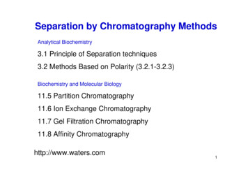
General modelling equation appliedρf dV P· Flux J A dtµ (Rm M Rc Lc )ρf·AdVdtJµ PRmRc mLcρfRc0 Flux J P0 R0 )µ (Rmc[kg.s 1 .m 2 ][kg.m 1 .s 1 ][Pa] [kg.m 1 .s 2 ][m.kg 1 ][m.kg 1 ][m][m][kg.m 3 ][m2 .kg 1 ][Illustration from Richardson and Harker, Ch8]permeate fluxpermeate viscosityTMP varies for different applicationsresistance through membrane (small)resistance through cake (large)membrane thicknesseffective cake thicknessfluid density“cake resistance”20
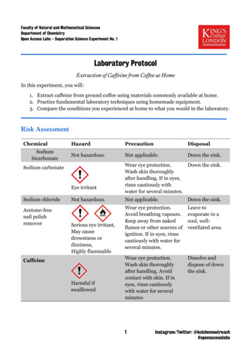
Flow patterns for microfiltrationDead-end flowCross-flow (TFF)IIIIonly for very lowconcentration feedselse becomes rapidlycloggedair filtration and virusremoval applicationsITFF tangential flow filtrationmain purpose?IIIIImicrofiltration: tends to havecake build upinduces shearing to erode cakemobile slurry for downstreamreduces cake resistance, Rc0Pin Pout P PP221
Dead-end flow vs cross-flow geometriesDead-end flowIcake thicknessincreases with time:Lc (t)Iimplies cakeresistance changeswith time: Rc0 (t)Iso for a constant P,implies J(t) falls offJ P Rc Lc )0µ (RmCross-flow (TFF)Ifluid velocity: 1 to 8 m.s 1tangentiallyIkeeps mass transfer resistance lowIfor a given P: TFF allows us toobtain higher fluxes than dead-end(usually P is 100 to 500 kPa)Icannot take lab test results with afilter cloth dead-end and apply it tocross-flow situation22
Cross-flow flowsheet[Illustration from Richardson and Harker, Ch8]How to pressurize the unit?1. Supply feed at pressure; valve at retentate to adjust/control P2. Draw a vacuum at permeate and pull material through membraneQuestion: why recycle the retentate stream?23
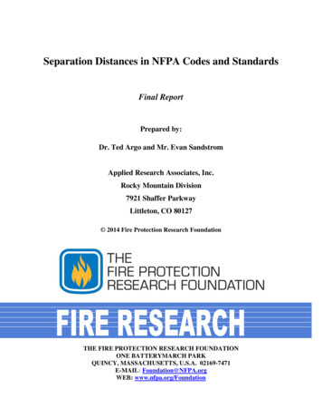
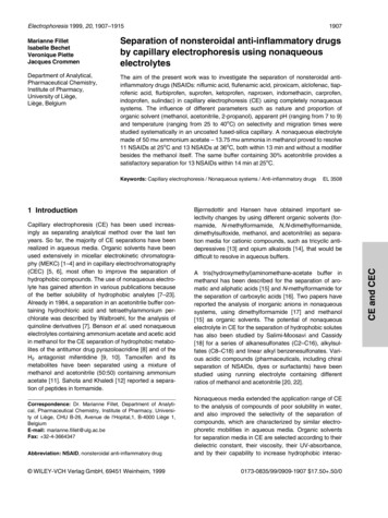
Dealing with foulinga. slow cross-flow velocityb. high cross-flow velocityc. high cross-flow with regular backwashing[Richardson and Harker, Ch8]24
Factors to improve fluxIincrease pressure differenceIregular backflushIchoose alternative membrane structureIfeed concentration kept lowIshear rate (velocity in cross-flow): reduces Rc0 Rc LcIincrease temperature of feedInature of the solids deposited: affects resistance Rc25
QuestionA microfiltration membrane operating with pure feed of waterproduces a flux of 0.06 kg.s 1 .m 2 when operated with a TMP of150 kPa.1. What is the resistance due to the membrane? Specify theunits.2. If operated with a protein-water mixture at a 200 kPa pressuredifference, a flux of 0.0216 kg.s 1 .m 2 is measured at steadystate. What is the resistance due to cake build-up? Specifythe units.3. Next, estimate the pressure drop required to achieve a flux of0.035 kg.s 1 .m 2 [Ans 325 kPa].To consider: are we likely to achieve fluxes of 0.1 kg.s 1 .m 2with this membrane? If not, how could we?26
A very crude estimate of the membrane resistance, Rm0IIAssume the pores are cylinders of diameter D with length MThe velocity in this tube for pure solvent isv II(D 2 )( P)32µ MConsider a 1 m2 surface of tube pore openings, where is thefraction of pore openings of diameter DThe total flux of solvent through all pores isJ v ρf IIHagen-Poiseulle P P(D 2 )( P) ρf 032 M32µ Mµ Rmµρf D 2 Note: true pores are of different sizes, they are not straightthrough the membrane; they bend and twist0 will always be too lowNote: this Rm27
Estimating the cake resistance, Rc : for dead-end filtrationExactly the same approach as we saw in the filtration section:1. Measure V (volume of permeate) against time t at a constantand known P2. The slope is related to α, the specific cake resistance [m.kg 1 ](we defined this in the filtration section)αCSV (t) will increase over time3. Rc0 (t) ρf A28
Ultrafiltration (UF)II5 nm to 100 nm (0.1 µm) particles areretained1 to 1000 kDa particles are retained(move to using molecular weight)III1 dalton 1 atomic mass unit1 kilodalton 1000 dalton 1000 g/molparticles with lower molecular weight,e.g. most solvents, pass throughIpore sizes: 1 to 20nmItypical fluxes:Jv 0.01 to 0.5 m3 .m 2 .hr 1Jv 10 to 500 L.m 2 .hr 1 (LMH)Iasymmetric structureIalmost always operated in TFF(cross-flow filtration)[Perry’s 8ed; Ch20.4]29
Ultrafiltration applicationsUF: loosely considered: “cross-flow filtration at molecular level”IRecovery of proteins and high molecular weight materials(solute)IPermanent emulsions: e.g. oil phase will not passIFine colloidal particles: e.g. paint/dyesILarge molecules of interest might remain in retentate;permeate discardedIe.g. albumin (egg white) concentratione.g whey processing (liquid “waste” after cheese-making):IIIIIcentrifuge UF reverse osmosis (RO)valuable proteins retained by UFpermeate sent to RO to concentrate smaller molecule sugarsand saltsthat RO concentrated permeate: used for ethanol and lacticacid production30
More terminologyIpermeate: the material passing through the membrane fromfeed to outlet sideIretentate: the material retained on the feed-side of themembraneIsolute: most often retained on the inside (feed side) of themembrane and deposited on the membrane wallIsolvent: the liquid phase that carries the soluteIgel effect: buildup of the solute on the membrane wall to forma high concentration gradient “gel”31
Ultrafiltration (UF)IIIIdriving force P of 0.1 to 1.0 MPa“tight”, low-permeability side faces the TFF to retain particlesthis skin layer is about 10µm thick; provides selectivity, Sopen, high-permeability side mainly for mechanical strengthCpermeateCfeedCpR 1 1 SCfR 1 MWCO: molecularweight whereR 0.9[Richardson and Harker, Ch8]i.e. 10% of thatmolecular weightpasses through tothe permeate32
Transport phenomena in UFIIIIIIIsolute (i.e. particles) carried towards membrane by solvent PJ Rm RcpRm membrane resistance [m.s 1 if J is mass flux]Rcp resistance due to “concentration polarization”Rcp effectively is the resistance due to solute boundary layerMass concentration Cb (in bulk), steadily increasing to Cw(wall)Units of C are kg solute per m3 solvent33
Transport phenomena in UFIIJ· C Jv CρfSolute flux out of membrane (leakage): Jv Cpermeate 0Solute flux towards membrane:Net transport of solute 3 m solventJv2 m .s kg soluteC3 solventm kg soluteJv C2 m .s kg soluteCp 0m3 solventJv (C Cp )volumetric flux of the permeatesolute mass concentration at a given pointsolute mass flux towards membranesolute mass concentration in permeate34
Diffusion termISolute diffusion away from membrane JdiffusionJdiffusion DAB m3 solvent m2 .s 1m.s kg solutem2 .sdCdy DABJdiffusionISee animation on Wikipediadiffusion of solute in solventsolute mass flux into bulk35
Transport at steady stateAt steady state: transfer towards membrane equals diffusion backdCJv (C Cp ) DABZ LcZ Cb dyJvdC dy DAB 0Cw C Cp lnCw CpCb Cp J v LcJv DABhw36
UF: mass-transfer key pointsAssuming Cp 0 (i.e. R 1)Jv LcJv lnDABhw CwCb where hw is a mass-transfer coefficient, with units of m.s 1I there are correlations forhw f (velocity, temperature, channel diameter, viscosity)I when gelling occurs, Cw Cg at the wallI the effect of increasing P isIIIIIIIincrease in solute flux towards boundary layerdiffusion increases to oppose itnet effect: almost zero (see earlier plot)experiments mostly agree with this theorythere is a limiting flux Jlim f (Cw , Cb , hw )at higher feed concentrations, lower fluxes if we are at/nearthe gel polarization state (gelling)typical diffusivities: 1 10 9 (fast!) to 1 10 11 m2 .s 137
Transport phenomena in UFIIIIIIIExperimental evidence agrees well with theory .
I Geankoplis, \Transport Processes and Separation Process Principles", 4th edition, chapter 7 (theory) and chapter 13. I Ghosh, \Principles of Bioseparation Engineering", chapter 11.