Transcription
http://www.BetaMachinery.comNEW API STANDARD 618 (5TH ED.) ANDITS IMPACT ON RECIPROCATINGCOMPRESSOR PACKAGE DESIGNAPI 618 5th Edition (the Standard) Only Specifies Minimum Requirements —More Aggressive and Innovative Approaches Can Realize Significant SavingsBy Shelley Greenfield, P.E. and Kelly EberleEditor’s Note: The new API Standard 618 (5th Edition) affects how packagers and owners design reciprocating compressor packages to avoid pulsation- and vibration-relatedproblems.Shelley Greenfield is vice president of Engineering DesignServices at Beta Machinery Analysis, Calgary, Alberta, Canada.She leads the company’s design teams, structural, foundationand skid design services, customer support and training initiatives. This includes managing relationships with Beta’s customers, OEMs and packagers in Asia, Europe and North/SouthAmerica. Greenfield has 23 years of direct experience in performing API 618-related design studies and actively participated on the API 618 Standard 5th edition pulsation task force.She has published technical articles and presented at varioustechnical conferences in North America and Europe. She received a BSc degr ee (Mechanical Engineering) fr om theUniversity of Calgary and is a Professional Engineer.Kelly Eberle is a principal engineer at Beta with over 20 years ofdesign and field experience, particularly in the ar ea ofpressure pulsation analysis and mechanical analysis of reciprocating compressor and pump installations, and structural analysis for offshore projects. The scope of his design experience includes acoustical simulations, ther mal flexibility studies,static and dynamic finite element analyses, structural analysisand foundation analysis. He directs Beta’s Research andDevelopment gr oup focusing on new analysis tools andtechniques. Eberle has published technical articles andpresented at the GMRC, EFRC and The Vibration Institute. He received his BSc degree in Mechanical Engineering from theUniversity of Saskatchewan.Changes to Pulsation, Vibration, Torsional, Skid,Engineering StudiesSummary of API Standard 618 and Key Changes inthe 5th Edition — API Standard 618 (the Standard) is therecognized specification for owners and manufacturers ofreciprocating compressors. The 4th Edition of API 618 waspublished in 1995. During the following 12 years, the industry identified many enhancements to this Standard,which were included in the new 5th Edition, published inDecember 2007. The Standard can be purchased on online at http://www.IHS.com.2008A key section of the Standard focuses on the design tocontrol pulsation and vibration for reciprocating compressorsystems, section 7.9. This section of the Standard is usedthroughout the industry, including high-speed machines.The purpose of API 618 is to establish minimum designrequirements. Later, in this presentation, API recommendsthat the user and manufacturer go beyond these minimumstandards and “aggressively pursue” designs that improveefficiency and minimize “total life-cycle costs (as opposedto acquisition cost alone).”The following points summarize key changes incorporated in the 5th Edition.Pulsation Analysis: For cases where the piping designis not available, the pulsation supplier can perform a “prestudy,” or damper check, to calculate bottle sizes.Suppliers should be aware of consequences to this approach (see below). Unbalanced force guidelines for piping and vessels are defined.Line side pulsation guideline has been updated to account for the specific speed of sound of the gas (now allows for higher pulsations in low-density gas and lowerpulsations in high-density gas).Allowable pressure drop criterion now includes a guideline for dynamic pressure drop as well as steady-statepressure drop.The pulsation analysis must consider the full range ofconditions including different gas analysis, all plannedoperating conditions and load steps.If multiple units are connected together through a common piping system, then a multi-unit analysis is requiredto ensure the cumulative pulsation effects are addressedand comply with standard.Vibration Control: To avoid resonance and excessive vibration, mechanical analysis of the compressor package isneeded to recommend modifications to the piping system.The forced response (formerly known as M6 and M7)studies are no longer required on all Design Approach 3(DA3) projects. These studies are only required if the pulsation and mechanical design do not meet the requiredguidelines. In addition, more specific instructions are provided on how these studies should be performed to ensureaccurate results.COMPRESSORTechTwo
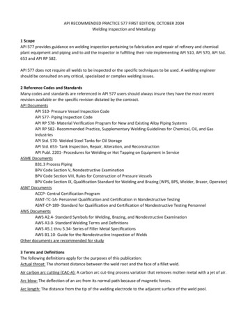
http://www.BetaMachinery.commore system parameters that affect pulsation and vibration2. The definition ofthe design approaches in the new 5thEdition is similar to the 4th Edition butwith some important differences. The5th Edition includes a description of thedesign criteria and the necessary stepsrequired to meet the various DesignApproaches. The revised Standard includes several flow charts to describethese steps and Design Approaches,which are complicated and can be difficult to interpret. Following is a simplified description of the DesignApproaches and analysis steps.The former M8 study (stress analysis of the bottle internals) is optional and is to be done only if specified by theowner.The margin of separation between the MechanicalNatural Frequency (MNF) and shaking force, or excitation, frequency is 20%. In addition, the minimum MNFmust be greater than 2.4 times maximum run speed.Vibration design guidelines have been added.The owner and packager are encouraged to exceedthese standards to improve efficiency and reduce total lifecycle costs. We refer to this as optimized design practices.Pulsation and Vibration Control (section 7.9 of theStandard): — There are three design approaches for pulsation and vibration control, which is consistent with the4th Edition. The new 5th Edition of the Standard no longeruses “M study” terminology to designate the separatestudy components (e.g., M2 for pulsation study, M3 forperformance analysis).The following application selection chart (see below) isnow included. The recommended design approach (DA) isbased on the compressor discharge pressure and ratedpower per cylinder.Selection Chart: For Pulsation/Vibration Study Scope(note: DA1 Design Approach 1, DA2 Design Approach2, DA3 Design Approach 3)A more detailed application selection chart, Beta’s RiskRating chart 1, has been developed to incorporate evenAbsolute Discharge PressureP 35 bar(P 500 psi)35 bar P 70 bar(500 psi P 1000 psi)70 bar P 200 bar(1000 psi P 3000 psi)200 bar P 350 bar(3000 psi P 5000 psi)Design Approach 1 (DA1, also Step1): The scope includes basic bottle sizing using empirical calculation. Thisdoes not include pulsation study (consistent with 4th Edition).Design Approach 2 (DA2, also Step2): The scope includes pulsation control design in conjunction with a mechanical review (basicvessel calculations and review pipe runs and anchoring system). Pulsations are to be analyzed with acoustic simulationto assess pulsation, forces and pressure drop. The DA2scope does not include mechanical modeling to calculateMNFs.The following simplified flow chart identifies two ways todesign the pulsation solution. The recommended approachprovides a more reliable, efficient and lowest overall pulsation control solution (compared with optional approach,discussed below), but requires piping layout information.The optional approach can be undertaken if bottlesmust be ordered before the piping system is defined.Initial bottle sizes are based on a pre-study, or dampercheck. This is an acoustical simulation of the gas passages and bottles based on a line connection with infinitelength. The drawback with this approach is that the packager/owner will have difficulty optimizing the pulsationcontrol solution once the final piping system is determined; pressure drop may be higher, bottles may need tobe redesigned, and additional pulsation analysis may beneeded at a later date to determine support requirements.Design Approach 3 (DA3): The scope includes Step 2:Pulsation analysis (per DA2 above) plus:Step 3a. Accurate Modeling of MNFs. Analyze compressor and piping system to avoid mechanical resonances atfrequencies where significant shaking forces exist. Thisstep was formerly known asM5 study of compressor manifold. The design shall meetRated Power per Cylindertwo key parameters:1. Separation Mar gin bekW/cyl 5555 kW/cyl 220220 kW/cyltween MNF and the shaking(hp/cyl 75) (75 hp/cyl 300) (300 hp/Cyl)force or excitation, frequency.Minimum MNF of any elementDA1DA2DA2in the system 2.4 maximumrun speed and predicted MNFDA2DA2DA3shall be separated from significant excitation frequenciesby 20%.DA2DA3DA32. Acoustic Shaking For cesshall not exceed the limitsDA3DA3DA3based upon the calculated effective static stiffness and the
http://www.BetaMachinery.comgenerally limited to specific areaswhere the forces exceed the guideline,or the mechanical design criteria cannot be met.Based on the writers’ experience thisstudy is seldom required for standardcompressor packages.There is a benefit to the packager orowner for conducting this analysis inspecific cases, such as:o New installations where bottle material has been purchased.o Existing installations where makingpipe layout, or support changes, aredifficult.o Design optimization studies whereanalyses have competing requirements.A typical example is the elevated piping around air coolers. The hot discharge piping requires a flexible designto minimize nozzle loads, but the mechanical requirements for minimum vibration requires a stiff design.design vibration guideline. API 618 defines a method for estimating the effective stiffness of the piping and the bottlewithout conducting comprehensive mechanical modeling.If design guidelines for Steps 2 and 3a are met, API618 DA3 is complete. If any of the guidelines are notmet, Steps 3b(1) and/or 3b(2) will be required to meetDA3 requirements.Forced response analysis may be required (contingenton Step 3a results) Step 3b(1). Compressor Mechanical Model Analysis(formerly called M6 study)This step applies to the pulsation suppression devices(bottles). If the separation margin or shaking force criteriain Step 3a, above, cannot be met, a forced responseanalysis of the compressor mechanical model must beconducted. The analysis is to include the pulsation shaking forces and cylinder gas forces. The design must meetthe allowable cyclic stress criteria.Note: The cylinder gas forces (also called frame stretch,or cylinder stretch forces) can cause excessive pulsationbottle vibrations even if the pulsation shaking forces meettheStandard.API 618 5th Edition does not provide any guidelines foracceptable cylinder gas forces. Based on the writers’ experience, the Compressor Mechanical Model Analysis inStep 3b(1) is required for medium to high speed unitswhen:o HP/cylinder 750 or rod loads exceed 80% rated rodload.o Wide speed range operation is required (more than25% of rated).o Compression ratio is below 1.7.o Compressor is in a critical application. Step 3b(2). Piping System Analysis (formerly called M7study)If the Separation margin, or shaking force criteria inStep 3a, above, cannot be met, a forced response analysisof the piping system to pulsation shaking forces must bedone.The design must meet the allowable cyclic stress criteria and vibration limits. Piping system may include allpiping included in the pulsation (acoustic) analysis, but isTorsional Vibration Analysis (TVA)The new 5th Edition states:“The compressor vendor shall perform the necessary lateraland torsional studies to demonstrate the elimination ofany lateral or torsional vibrations that may hinder theoperation of the complete unit within the specified operating speed range in any specified loading step.”Typically, lateral critical studies are not required forreciprocating compressor applications. Lateral natural frequencies will be positioned well above significant torsional natural frequencies, or any forcing frequenciesgenerated by the compressor or driving equipment.The new 5th Edition also states:“The compressor vendor shall provide a torsional analysisof all machines furnished (except small belt units). Thestudy shall eliminate any harmful lateral or torsional vibrations for all specified speed ranges and loading steps.”A stress analysis shall be performed if the torsional resonance falls close to the torsional natural frequency. Thestress analysis is to ensure that the resonance will not beharmful for the compressor system.The TVA report includes data used in mass elastic system,display of forces vs. speed (and frequency), torsional criticalspeed and deflections (mode shape diagram), worst-casedesign and upset condition results including failed compressor valves, engine misfire and worn damper cases. The report should also consider how the input data variance willaffect the results.Dynamic Skid AnalysisThe dynamic skid study (including forced responseanalysis) is outlined in section 7.5.4.14 of the Standard, andis strongly recommended for packages mounted on offshore platforms or modules mounted on steel columns.At Beta Machinery Analysis, we recommend that a dynamic skid analysis is also conducted for, new or unproven skid designs; two throw, high-speed, variable speed compressors;and skids mounted on concrete foundations (and gravelpads) where the local soil conditions are suspect.
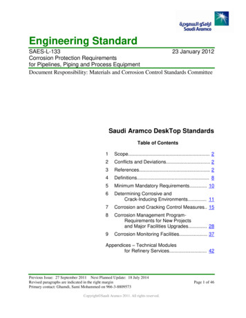
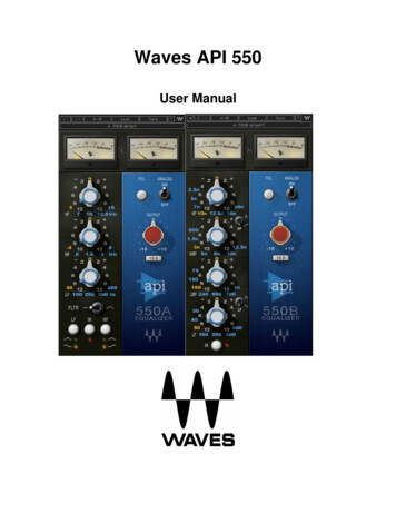
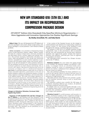
http://www.BetaMachinery.comAlthough not part of API 618, a skid lifting study, transitstudy, and environmental loading analysis, are often required. Beta recommends that the same party conduct allskid studies.Implications for Foundation Design orPlatform/FPSO StructuresWhile not addressed in this Standard, the assumption isthat the owner has specified a foundation design includingdynamic analysis of shaking forces and the interaction ofloading on the gravel, pile or concrete foundation. For offshore production platforms or FPSOs, the dynamic analysisof the compressor, skid and structure becomes even moreimportant. Dynamic analysis of reciprocating compressorfoundations requires specialized knowledge, experienceand simulation tools. The party chosen to conduct thefoundation design must be carefully selected.The accuracy of the dynamic skid analysis is stronglyinfluenced by the design of the foundation for offshoreinstallations or onshore pile installations. The dynamicskid analysis must include modeling and simulation of thefoundation at the same time. Separate dynamic analysis ofthe skid and foundation cannot be done accurately.3Piping Flexibility (Thermal) AnalysisSections 7.9.4.2.3.6 and 7.9.4.2.5.2.5.2 of the Standard refer to the piping system design, including the effect of piping movements due to temperature changes as well asweight, pressure and other factors. The thermal designoften requires that flexibility be added to the system. Thisrequirement is counter to the requirement for more support(increased stiffness) to meet the MNF designrequired. It is recommended that the same party conductingthe DA2 or DA3 study to control vibration, also conduct thepiping flexibility study. The purpose of this is to minimizedesign iterations and result in an overall optimized design.The Thermal Analysis (formerly M11 study) is specifiedas optional in the 5 th Edition. Beta recommends thisanalysis be conducted to the compressor package whenthe cooler is off-skid, when there are multiple compressorpackages on a common header, when the installation willexperience extremely cold ambient temperatures, or forcompressors that operate over a very wide range of conditions (one-stage or two-stage operation).SummaryThe new API 618 5th Edition includes many improvements over the 4th Edition in the specification for engineering studies to minimize pulsation and vibration.These new specifications have an impact on packagersand owners. Also, the revised Standard has some areas inthe specification that require interpretation by engineering service providers.Part II of this article expands on some of these impacts tousers and packagers.Footnotes1Find Beta’s Risk Rating Chart on our website(www.BetaMachinery.com Support Risk Rating Chartand Specification Guide).2Beta’s Application Note #2 also provides guidelines tohelp decide which study scope is recommended. (seewww.BetaMachinery.com Support Application Notes).3For more information on dynamic analysis for offshorestructures, such as FPSO, refer to the article, “DynamicAnalysis of Reciprocating Compressors on FPSO TopsideModules,” which was delivered at the 5th European Forumfor Reciprocating Compressors Conference in 2007. Thearticle, reprinted from COMPRESSORTechTwo magazine, is a freedownload from our website (www.betamachinery.com Support Articles).Implications of the New API 618(5th Edition) for Packagers,OEMs and OwnersOverview of medium or large horsepower reciprocatingcompressor systems typically requires a pulsation and vibration design study as outlined in API 618 (the Standard)5th Edition. These studies have proven to mitigate the riskof excessive vibration and avoid costly repair, maintenanceand downtime costs. When specifying an API 618 pulsationand vibration study, the packager and owner must beaware of the following four issues:1. Cylinder stretch force guidelines are mentioned, however, the Standard does not provide any guidelines for acceptable cylinder gas forces. These forces must be assessedin a study since they can be a significant source of excitation at all orders of compressor speed.2. Mechanical design for medium- and high-speed machines represents challenges in meeting API 618 design specifications. The stiffness of scrubbers and other componentsneeds to be much higher than with slower-speed machinesto meet the Mechanical Natural Frequency (MNF) guideline.3. The vibration study requires accurate models of themechanical system. Note that the Standard does notspecify how to ensure accurate models. Analysis andmodeling techniques are, in many areas, left to the engineering service provider. In this section, four key areasare discussed that contribute to poor results and are tobe avoided.4. Reviewing supplier quotations for a Design Approach3 (DA3) study can be confusing, especially when considering a forced response analysis. This confusion can lead toexcessive scope and study costs.These four issues are discussed and include recommended specifications for purchasing a pulsation and vibration study that ensures reliability (for owners), lesswarranty costs (for packagers), and a level playing fieldwhen quoting on projects (for vibration consultants).Later, Beta Machinery Analysis (Beta) provides suggestionsto reduce the total cost and improve efficiency of compressor packages.Cylinder Stretch Forces Must Be Addressed in theDesignBeta Machinery Analysis (Beta), and other leading experts,has long recognized that the forces acting on the inside ofthe compressor cylinder are a significant source of excitationat all orders of compressor run speed. These forces cause thecompressor cylinder to move away from, and toward, thecompressor frame. This motion is commonly called framestretch or cylinder stretch. See Figure 1.Cylinder stretch motion can cause high-frequency vibrations on the bottles and piping close to the compressor1.These forces are mentioned briefly in the 5th Edition of theStandard, but no guidelines are specified. Beta, as well assome other vibration consultants, has developed field-testedguidelines to assess cylinder stretching forces and their potential for causing vibration. During a DA3 study, the vibration consultant will assess the fundamental vibration modesfor pulsation bottles at higher orders of compressor speed,and include cylinder stretch forces.Factors such as power per cylinder, rod load, speedrange and others are strong indicators that cylinder stretchrelated vibration problems are likely, and that a forced response analysis is warranted (Step 3b1, forced responseanalysis of the compressor mechanical model).
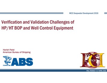
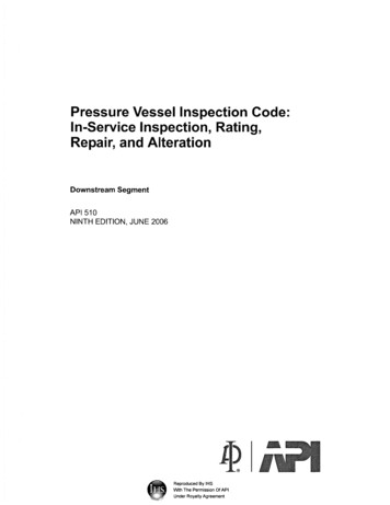
Cylinder Stretching Forcehttp://www.BetaMachinery.compistoncylinder Figure 1: Cylinder stretching force is caused by high internal gasforces acting on the inside of the compressor cylinder. These forcescan be a significant source of excitation at all orders of compressorrun speed.Mechanical Design to Meet API 618 (5th Edition)To avoid vibration problems, the vibration consultantadjusts the MNFs of the system to avoid resonance. The5th Edition includes two specifications relating to component MNFs:Minimum MNF Guideline — The MNF of bottles, pipingand cylinders must be above 2.4 x compressor run speed(Mechanical Design Goal) as shown in Figure 2.This figure illustrates that the forces in a variable speedunit (red arrows) will occur across a wide frequency range,making it difficult to design a scrubber with an MNF between 1x and 2x run speed. Moving the MNF above 2.4 xrun speed will avoid resonance problems.The Minimum MNF Guideline represents a challenging design requirement for high-speed compressors (1200 to 1800rpm). In general, the piping or vessels must be much stifferthan in slower-speed units. Early communication betweenthe compressor packager, owner and vibration consultant isnecessary to ensure acceptable vessel and skid designs.Table 1 illustrates the Minimum MNF Guideline for different maximum compressor speeds.For slow- and medium-speed units, the Minimum MNFGuideline is not a difficult design problem. For high-speedmachines, however, the design becomes much more challenging. Table 2 below explains why.Separation Margin Guideline — The Standard specifiesa separation margin of 20% is required between the calculated MNFs and significant excitation frequencies.This separation margin requirement can create problems.The term “significant excitation,” that is, a force amplitude,is not defined in the Standard. Also, the “frequencies” to beconsidered and guidelines for cylinder stretching forces arenot defined in the Standard.Beta’s interpretation of the separation margin guideline isthat it applies to frequencies over 2.4 x run speed. Themain sources of “significant excitation” are forces frompressure pulsations and the cylinder stretch forces.The vibration consultant needs to conduct a pulsationanalysis to control dynamic forces in the bottles and piping. API has developed force guidelines proven to resultin successful designs and controlling vibrations from pulsation forces.As discussed under “Cylinder Stretch Forces Must beAddressed in the Design,” above, the vibration consultantneeds to calculate the cylinder stretch forces as a first step.If the cylinder stretch forces are above a certain level, acompressor mechanical model analysis (Step 3b1, formerlycalled M6 study) is required. The second step in assessingthe cylinder stretch forces is evaluating the mode shapescalculated in the mechanical analysis. Certain pulsation bottle mode shapes are known to be very responsive to cylin- Figure 2: Move MNF above 2.4 x run speed to avoid resonance.Minimum MNF for Compressor System(based on different run speeds)Maximum Run Speed(rpm)(Hz)Minimum MNF Guideline9001536 Hz12002048 Hz18003072 Hz Table 1.der stretch forces. These modes must meet the 20% separation margin criteria, or a compressor mechanical modelanalysis should be conducted.It may be very difficult to meet the 20% separation margin criterion in some cases, such as variable speed compressors. The cylinder stretch forces are constant for eachorder of compressor speed, that is, the forces have a fixedamplitude over a wide frequency range. A compressor mechanical model analysis is required in these cases. A riskanalysis can be done in the bid stage to identify whenthese studies are likely required.Mechanical Design TipsFabrication practices such as installation and mountingdetails to the skid are very important to provide the required stiffness of scrubbers and other components. Skiddrawings and mounted details must be available at the timeof the mechanical analysis.As vessel design (length vs. diameter) vs. mounting design can dramatically affect MNFs, vessel fabrication drawings must also be available at this time.Accurate Finite Element Analysis (FEA) modeling techniques that closely match the real MNFs must be used.Shortcuts in modeling create high risk — see “FactorsAffecting Accuracy of Vibration Analysis,” below. Modelingtechniques must be field verified.In some cases, it may be impractical to reach these highfrequencies. Inter-tuning can be an option if approved bythe owner and packager2.Early involvement between the packager and vibrationconsultant is highly recommended to discuss mechanical
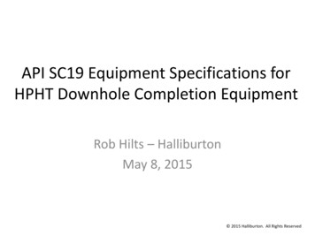
http://www.BetaMachinery.comCompressor Component(example only)Typical MNF(standard configurations)Scrubbers15 to 30 HzRun SpeedThat May ViolateAPI 618 SeparationMargin Guideline 375 to 750 rpmCylinders30 to 50 Hz 750 to 1250 rpmBottles40 to 70 Hz 1000 to 1750 rpmPiping System40 to 90 Hz 1000 rpmCost/DesignImplications if MNFsMust be Moved HigherExtra costs to add bracesor change scrubber designPotential need foroutboard supportsBottle supportsmay be necessaryPipe braces or pipe layoutchanges may be necessary Table 2.design options. This involves input from the owner on theamount of vibration risk that is acceptable and avoids costlychanges later.Factors Affecting Accuracy of Vibration AnalysisAPI 618 5th Edition gives some general direction for performing simulations and modeling. However, accurateanalysis requires that specific details and techniques beused. Different levels of quality exist in the industry (buyerbeware). Following, are four key areas that affect accuracy:Pulsation Analysis — Numerous technical articles document that Time Domain (TD) algorithms provide superioraccuracy over the older Frequency Domain (FD) algorithms. In addition to better accuracy, TD algorithms cancalculate both static and dynamic pressure drop. This isnecessary to assess overall pressure drop and performancethroughout the system. FD algorithms are not able to calculate dynamic pressure drop. Dynamic pressure drop calculations are a requirement of API 618 5th Edition.Scrubber MNF Calculations — FEA is required in DA3studies to determine the MNFs for each component in thesystem. For scrubbers, the most important factor in the FEAmodel is the boundary condition assumption between thescrubber and the skid. Figure 3 illustrates the detailsneeded for accurate analysis (mounting plate, bolts, beamsand local skid construction).Simplistic FEA models will assume a rigid scrubber baseor generic estimate of stiffness. Beware of models with“rigid support” or “anchor” or “assumed stiffness.” Thesehave proven to be inaccurate and are to be avoided. Casestudies are available illustrating that over 15% error is associated with simplistic models. High error can mean high vibration and failures, or excessive costs (conservative mechanical design).Compressor Stiffness Assumptions — Because of highgas forces, the compressor frame cannot be considered arigid body for dynamic studies, even when mounted onconcrete. Accurate stiffness assumptions are required whenmodeling the compressor MNFs (DA3, Step 3a) and forcedresponse analysis of the compressor and bottles (Step 3b1).For superior accuracy, Beta has developed a “super element model” of the compressor frame, which is included inthe FEA analysis of the system (see Figure 4). The improved accuracy can reduce the need for costly mechanicalsupports and braces4.Pulsation Bottle Nozzle Flexibility — Pulsation bottleMNF depends on nozzle connection flexibility (see Figure5). All mechanical models must employ 3-D FEA techniquesto calculate shell flexibility accurately. Simplified assumptions are not valid.Confusion in Quoting DA3 StudiesAs discussed in Part I of this series, the DA3 may requirea forced response analysis if the results of the pulsationanalysis and the mechanical analysis (MNF modeling) donot meet guidelines. This creates confusion in the quotationphase, because it is uncertain if the forced response analysis will be required and what the associated cost will be ofthese contingencies. Also, the scope of the forced responsestudy may not be apparent during the quotation phase.Depending on the situation, the scope of the study, or studies, could be small, or quite large. There are two possibleforced response studies to consider.Compressor Mechanical Model Forced ResponseStudy — (Step 3b1) is typically required for medium- tohigh-speed units when: hp/cylinder 750, or rod loads exceed 80% rated rod load, wide speed range operation is required (more than 25% of rated), compression ratio is below 1.7, or there are critical applications (remote location,high availability required).Piping System Forced Response Study (Step 3b2):This analysis is seldom required for standard compressorpackages for the following two reasons: the pulsation de- Figure 3: FEA model(scrubber) must includebase details as shown:mounting plate, bolts,beams and local skidconstruction.
http://www.BetaMachinery.comInclude cylinder stretch forces and vibration assessment in DA3 studies.Option: for projects requiring high accuracy, themechanical analysis should include the compressorframe in the mechanical model.TipsGiven the confusion on forced response studies,we recommend the following three tips for obtaining DA3 study quotations from vibration consultants:Obtain a firm quote on DA3, Step 3a. Comparesuppliers based on this price.Determine likelihood of forced response analysisStep 3b (1 and 2). Supply optional prices for thesestudies if required.Complete a Risk Rating Assessment3 for the compressor. This is a good practice for defining the riskparameters with the unit.Early involvement between the packager and vibration consultant is recommended to discuss pulsationand mechanical de
Summary of API Standard 618 and Key Changes in the 5th Edition —API Standard 618 (the Standard) is the recognized specification for owners and manufacturers of reciprocating compressors. The 4th Edition of API 618 was published in 1995. During the following 12 years, the