Transcription
HIGH-TEMPERATURE ALLOYSHAYNES 25 alloyA Co-Ni-Cr-W alloy thatcombines excellent hightemperature strength withgood oxidation resistance.ContentsH-3057CChemical Compositionand Principal Features3Creep and StressRupture Strength4Typical Tensile Properties6Cold-Worked Properties7Impact Strength9Thermal Stability9Typical Physical Properties10Metal-to-MetalGalling Resistance12Hot Hardness Properties12Aqueous Corrosion Resistance12Oxidation Resistance13Sulfidation Resistance14Fabrication Characteristics15Welding17Health and SafetyInformation17Machining18 1997 Haynes International, Inc.
PRINCIPAL FEATURESExcellent High-TemperatureStrength and GoodOxidation ResistanceHAYNES 25 alloy is a cobaltnickel-chromium-tungstenalloy that combines excellenthigh-temperature strength withgood resistance to oxidizingenvironments up to 1800 F(980 C) for prolonged exposures, and excellent resistance to sulfidation. It can befabricated and formed byconventional techniques, andhas been used for castcomponents. Other attractivefeatures include excellentresistance to metal galling.FabricationHAYNES 25 alloy has goodforming and welding characteristics. It may be forged orotherwise hot-worked, providing that it is held at 2200 F(1205 C) for a time sufficient tobring the entire piece totemperature. The alloy hasgood ductility, and thus alsomay be formed by coldworking. The alloy does workharden very rapidly, however,so frequent intermediateannealing treatments will bein the form of plate, sheet,strip, billet, bar, wire, coatedelectrodes, pipe and tubing.needed for complex componentforming operations. All hot- orcold-worked parts should beannealed and rapidly cooled inorder to restore the best balance of properties. The alloycan be welded by both manualand automatic welding methods, including gas tungsten arc(GTAW), gas metal arc (GMAW),shielded metal arc, electronbeam and resistance welding.It exhibits good restraint welding characteristics.ApplicationsHAYNES 25 alloy combinesproperties which make itsuitable for a number ofcomponent applications in theaerospace industry, includingparts in established militaryand commercial gas turbineengines. In modern engines, ithas largely been replaced bynewer materials such asHAYNES 188 alloy, and, mostrecently, 230 alloy, whichpossess improved properties.Another area of significantusage for 25 alloy is as abearing material, for both ballsand races.Heat TreatmentWrought HAYNES 25 alloy isfurnished in the solution heattreated condition, unlessotherwise specified. The alloyis normally solution heat-treatedat 2150 to 2250 F (1175 to1230 C) and rapidly cooled orwater-quenched for optimalproperties. Annealing attemperatures less than thesolution heat-treating temperature will produce some carbideprecipitation in 25 alloy, whichmay affect the alloy’s properties.Applicable SpecificationsHAYNES 25 alloy is coveredby the following specifications:AMS 5537 (sheet, strip andplate), AMS 5759 (bar, ringsand forgings), AMS 5796(welding wire), and AMS 5797(coated welding electrodes).The UNS number for thismaterial is R30605.Available in Convenient FormsHAYNES 25 alloy is producedNOMINAL CHEMICAL COMPOSITION, PERCENTCo aNiCrWFeMnSiC511020153*1.50.4*0.10*Maximum aAs balance1997 Haynes International, Inc.3HAYNES 25 alloy
CREEP AND STRESS-RUPTURE STRENGTHHAYNES 25 alloy is a solidsolution-strengthened materialwhich possesses excellenthigh-temperature strength. It isparticularly effective for verylong-term applications attemperatures of 1200 to 1800 F(650 to 980 C). It is strongerthan nickel-base solid-solutionstrengthened alloys, and is thestrongest of the cobalt-basematerials which still have goodfabrication characteristics.COLD-ROLLED AND 2200 F (1205 C) SOLUTION-ANNEALED SHEET*TestTemperature F ( C)1200 (650)1300 (705)1400 (760)1500 (815)1600 (870)1700 (925)1800 (980)Approximate Initial Stress, Ksi (MPa)Creep%to Produce Specified Creep in:10 Hrs.100 Hrs.1,000 Hrs.0.562.0 (425)47.5 (330)33.5 (230)1.071.0 (490)54.0 (370)39.0 (270)Rupture82.0 (565)69.0 (475)57.0 (395)0.543.0 (295)30.0 (205)21.0 (145)1.049.5 (340)35.0 (210)23.2 (160)Rupture64.0 (440)50.0 (345)38.0 (260)0.528.0 (195)19.5 (135)14.8 (100)1.032.0 (220)21.5 (150)16.2 (110)Rupture47.0 (325)36.0 (250)26.0 (180)0.518.5 (130)14.0 ( 97)10.2 ( 70)1.020.2 (140)15.5 (105)12.3 ( 85)Rupture34.0 (235)24.7 (170)18.1 (125)0.513.7 ( 94)9.9 ( 68)6.9 ( 48)1.015.2 (105)12.0 ( 83)8.9 ( 61)Rupture24.0 (165)17.5 (120)12.0 ( 83)0.59.7 ( 67)6.8 ( 47)4.5 ( 31)1.012.0 ( 83)8.8 ( 61)5.6 ( 39)Rupture17.3 (120)11.8 ( 81)7.2 ( 50)0.56.8 ( 47)4.5 ( 31)2.6 ( 18)1.08.8 ( 61)5.6 ( 39)3.0 ( 21)Rupture11.8 ( 81)7.2 ( 50)4.0 ( 28)*Based upon limited data.HAYNES 25 alloy4
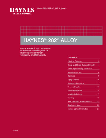
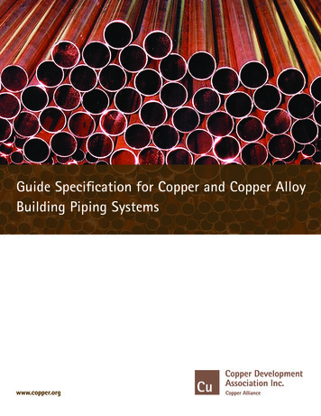
CREEP AND STRESS-RUPTURE STRENGTHHOT-ROLLED AND 2250 F (1230 C) SOLUTION-ANNEALED BARTestTemperature F ( C)Approximate Initial Stress, Ksi (MPa)to Produce Specified Creep in:10 Hrs.100 Hrs.1,000 Hrs.Creep%1350 (730)0.51.0Rupture1500 (815)42.5 (295)36.5 (250)30.3 (210)30.0 (205)22.0 (150)17.0 (115)23.0 (160)16.5 (115)12.0 ( 83)17.0 (115)12.0 ( 83)8.4 ( 58)11.5 ( 79)7.5 ( 52)5.0 ( 34)0.51.0Rupture1600 (870)0.51.0Rupture1700 (925)0.51.0Rupture1800 (980)0.51.0RuptureCOMPARATIVE RUPTURE STRENGTH, SHEET25175STRESS TO RUPTURE IN 1,000 HOURSStress, Ksi20150(All Materials Solution Annealed)125151001700 F (925 C)7510Stress, MPa1500 F (815 C)5050252518823025X5188230X0HAYNES 25 alloy
TYPICAL TENSILE PROPERTIESCOLD-ROLLED AND 2200 F (1205 C) SOLUTION-ANNEALED SHEET*TestTemperature F CRoomUltimateTensileStrengthKsiMP a0.2% YieldStrengthKsiMP aElongationin 2 in. (51 18009803423518125362000109523160117648*Limited dataHOT-ROLLED AND 2250 F (1230 C) SOLUTION-ANNEALED BAR*TestTemperature F CRoomUltimateTensileStrengthKsiMP a0.2% YieldStrengthKsiMP aElongationin 2 in. (51 1800980281951913041*Limited dataVACUUM INVESTMENT CASTINGS — SOLUTION TREATED*TestTemperature F CUltimateTensileStrengthKsiMP a0.2% YieldStrengthKsiMP 701800980Elongationin 5D%Reductionin 24165253128195231602434*Limited dataHAYNES 25 alloy6
COLD-WORKED PROPERTIESHAYNES 25 alloy has excellent strength and hardness characteristics in the cold-worked condition.These high property levels are also evident at elevated temperature, making 25 alloy quite suitable forapplications such as ball bearings and bearing races. A modest additional increase in hardness andstrength can be achieved through aging of the cold-worked material.TYPICAL TENSILE PROPERTIES, COLD-WORKED SHEET*ColdReduction101520TestTemperature F CUltimateTensileStrengthKsiMPa0.2% YieldStrengthKsiMPaElongationin2 in. (51 760107740966603180098041285302054*Limited data for cold-rolled 0.050-inch (1.3 mm) thick sheet7HAYNES 25 alloy
COLD-WORKED PROPERTIESTYPICAL TENSILE PROPERTIES, COLD-WORKED AND AGED SHEET*TestTemperature F CConditionUltimateTensileStrengthKsiMP a0.2% YieldStrengthKsiMP aElongationin2 in. (51 mm)%15% CW7020168116013694031 Age 511040129890191200650144995128885820% CW Age 3323057020191131516211151660031516511401329102820% CW1000540149102512485523 Age 4905034591800980422903121512*Limited data for cold-rolled 0.050-inch (1.3 mm) thick sheet.Age A 700 F (370 C)/1 hourAge B 1100 F (595 C)/2 hoursTYPICAL HARDNESS AT 70 F (20 C), COLD-WORKED AND AGED SHEET*Hardness, Rockwell C, After Indicated Level ofCold Work and Subsequent Aging Treatment900 F (480 C)1100 F (595 C)5 Hours5 4320444447*Limited data for cold-rolled 0.070-inch (1.8 mm) thick sheet.HAYNES 25 alloy8
IMPACT STRENGTH PROPERTIES, PLATETypical Charpy V-NotchImpact ResistanceTestTemperature F ( C)-321 (-196)Ft.-lbs.109Joules148-216 (-138)134182-108 ( -78)156212-20 ( -29)179243Room193262500 (260)2192971000 (540)2012731200 (650)1702301400 (760)1431941600 (870)1201631800 (980)106144THERMAL STABILITYWhen exposed for prolonged periods at intermediate temperatures, HAYNES 25 alloy exhibits a loss ofroom temperature ductility in much the same fashion as some other solid-solution-strengthened superalloys, such as HASTELLOY X alloy or alloy 625. This behavior occurs as a consequence of theprecipitation of deleterious phases. In the case of a 25 alloy, the phase in question is Co2W laves phase.HAYNES 188 alloy is significantly better in this regard than 25 alloy; however, for applications wherethermal stability is important, 230 alloy is an even better selection.ROOM-TEMPERATURE PROPERTIES OF SHEET AFTER THERMAL EXPOSURE*ExposureTemperature F ( C)None1200 (650)1400 (760)1600 (870)UltimateTensileStrengthKsiMP aHours0.2% YieldStrengthKsiMP 187077.35353.51000142.098081.75655.0*Composite of multiple sheet lot tests.9HAYNES 25 alloy
TYPICAL PHYSICAL PROPERTIESDensityMelting RangeTemp., FRoom2425-2570British Units0.330 lb/in3Temp., CRoom1330-1410Metric Units9.13 g/cm 3ElectricalRoom34.9 µohm-inRoom88.6µohm-cmResistivity20035.9 µohm-in10091.8µohm-cm40037.6 µohm-in20095.6µohm-cm60038.5 µohm-in30097.6µohm-cm80039.1 µohm-in40098.5µohm-cm100040.4 µohm-in500100.8µohm-cm120041.8 µohm-in600104.3µohm-cm140042.3 µohm-in700106.6µohm-cm160040.6 µohm-in800107.8µohm-cm180037.7 µohm-in900101.1µohm-cm1000Thermal ConductivityRoomBTU-in/ft2 hr- F2Room95.0 µohm-cm9.4 W/m-K20075BTU-in/ft hr- F10010.9 W/m-K40090BTU-in/ft2 hr- F20012.9 W/m-K230014.8 W/m-K2600105BTU-in/ft hr- F800120BTU-in/ft hr- F40016.8 W/m-K1000135BTU-in/ft2 hr- F50018.7 W/m-K21200150BTU-in/ft hr- F60020.7 W/m-K1400165BTU-in/ft2 hr- F70022.6 W/m-K80024.7 W/m-K90026.9 W/m-K100029.2 W/m-K16001800HAYNES 25 alloy651822002BTU-in/ft hr- F2BTU-in/ft hr- F10
TYPICAL PHYSICAL PROPERTIES (continued)Temp., FBritish UnitsTemp., CMetric UnitsMean Coefficient of70-2006.8microinches/in- F25-10012.3µm/m- CThermal Expansion70-4007.2microinches/in- F25-20012.9µm/m- C70-6007.6microinches/in- F25-30013.6µm/m- C70-8007.8microinches/in- F25-40014.0µm/m- C70-10008.0microinches/in- F25-50014.3µm/m- C70-12008.2microinches/in- F25-60014.6µm/m- C70-14008.6microinches/in- F25-70015.1µm/m- C70-16009.1microinches/in- F25-80015.8µm/m- C70-18009.4microinches/in- F25-90016.5µm/m- C70-20009.8microinches/in- F25-100017.0µm/m- C25-110017.6µm/m- CDYNAMIC MODULUS OF ELASTICITYDynamicModulus ofElasticity,106 psiTemp., CDynamicModulus 1541000146Temp, F11HAYNES 25 alloy
METAL-TO-METAL GALLING RESISTANCEHAYNES 25 alloy exhibits excellent resistance to metal galling. Wear results shown below were generatedfor standard matching material room-temperature pin on disc tests. Wear depths are given as a function ofapplied load. The results indicate that 25 alloy is superior in galling resistance to many materials, and issurpassed only by ULTIMET alloy and HAYNES 6B alloy. Both of these materials were specifically designed to have excellent wear resistance.Material6B alloyRoom-Temperature Wear Depth For Various Applied Loads3,000 lbs. (1,365 Kg)6,000 lbs. (2,725 Kg)9,000 lbs. (4,090 ET alloy0.112.90.112.70.0825 alloy188 alloy0.235.91.5439.2HR-160 alloy1.73214 alloy556 .48139.3230 alloy4.44112.77.71195.88.48215.5HR-120 alloy6.15156.27.05179.010.01254.2 2.0HIGH-TEMPERATURE HARDNESS PROPERTIESThe following are results from standard vacuum furnace hot hardness tests. Values are given in originallymeasured DPH (Vickers) units and conversions to Rockwell C/B scale in parentheses.70 F (20 C)Vickers Diamond Pyramid Hardness (Rockwell C/B Hardness)800 F (425 C) 1000 F (540 C) 1200 F (650 C)1400 F (760 C)Solution Treated251 (RC22)171 (RB87)160 (RB83)150 (RB80)134 (RB74)15% Cold Work348 (RC35)254 (RC23)234 (RB97)218 (RB95)-20% Cold Work401 (RC41)318 (RC32)284 (RC27)268 (RC25)-25% Cold Work482 (RC48)318 (RC32)300 (RC30)286 (RC28)-AQUEOUS CORROSION RESISTANCEHAYNES 25 alloy was not designed for resistance to corrosive aqueous media. Representative averagecorrosion data are given for comparison. For applications requiring corrosion resistance in aqueous environments, ULTIMET alloy and HASTELLOY corrosion-resistant alloys should be considered.1% HCl (Boiling)ULTIMET alloy C-22 alloyAverage Corrosion Rate, mils per year (mm per year)10% H 2SO4 (Boiling)65% HNO 3 (Boiling) 1( 0.03)99(2.51)6(0.15)3(0.08)12(0.30)134(3.40)25 alloy226(5.74)131(3.33)31(0.79)Type 316L524(13.31)1868(47.45)9(0.23)HAYNES 25 alloy12
OXIDATION RESISTANCEHAYNES 25 alloy exhibits good resistance to both air and combustion gas oxidizing environments, andcan be used for long-term continuous exposure at temperatures up to 1800 F (980 C). For exposures ofshort duration, 25 alloy can be used at higher temperatures. Applications for which oxidation resistanceis a serious consideration normally call for newer, more capable materials such as 230 alloy or HAYNES188 alloy. This is particularly important at temperatures above 1800 F (980 C).COMPARATIVE BURNER RIG OXIDATION RESISTANCE1000 HOUR EXPOSURE AT 1800 F (980 C)MetalLos sAverageMetal AffectedMaximumMetal AffectedMaterialMilsµmMilsµmMilsµm230 alloy0.8202.8713.589HAYNES 188 alloy1.1283.5894.2107HASTELLOY X alloy2.7695.61426.4153Alloy 6254.91247.11807.619325 alloy6.21578.32118.7221Alloy 6172.7699.824910.7272Alloy 800H12.331214.536815.3389Type 310 Stainless Steel13.734816.241116.5419Alloy 60012.331214.436617.8452Oxidation Test ParametersBurner rig oxidation tests wereconducted by exposingsamples 3/8 in. x 2.5 in. xthickness (9 mm x 64 mm xthickness), in a rotating holder,to products of combustion ofNo. 2 fuel oil burned at a ratio ofair to fuel of about 50:1. (Gasvelocity was about 0.3 mach).Samples were automaticallyremoved from the gas streamevery 30 minutes and fancooled to near ambient temperature and then reinsertedinto the flame tunnel.COMPARATIVE OXIDATION RESISTANCE IN FLOWING AIR*Average Metal Affected in 1008 Hours**2000 F (1095 C)2100 F (1150 C)MilsµmMilsµmMaterial1800 F (980 C)MilsµmHAYNES 188 alloy0.615230 alloy0.7181.3333.48625 alloy0.71810.225919.2488Alloy 6250.7184.812218.2462X alloy0.9232.7695.8147Alloy 6171.3331.8463.4861.3338.0203* Flowing air at a velocity of 7.0 ft./min. (213.4 cm/min.) past the samples. Samples cycled to room temperature once-a-week.** Metal Loss Average Internal Penetration.13HAYNES 25 alloy
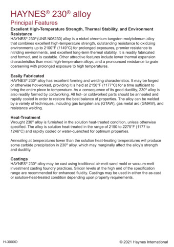
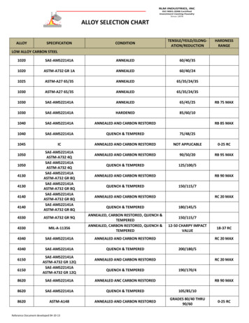
OXIDATION RESISTANCECOMPARATIVE BURNER RIG OXIDATION RESISTANCE AT 2000 F (1095 C) FOR 500 HOURSOXIDATION DAMAGE, µm0100200300400230 ation188 alloyX alloy( 25 mils in 165 hours)25 alloy0510152025OXIDATION DAMAGE, MILS3035SULFIDATION RESISTANCE AT 1400 F (760 C)a severe test, with equilibriumsulfur partial pressure of 10-6 to10-7 and oxygen partial pressures less than that needed toproduce protective chromiumoxide scales.Average Metal Affected (Mils)16 29 Mils400215 hours @ 1400 F (760 C)Ar-5% H2-5% CO-1% CO2-0.15% H2S-0.1% H2014123001082006410020 HR-160HAYNES 25 alloy25188 556031014617800H625XAverage Metal Affected (µm)in a gas mixture consisting of5 percent H2, 5 percent CO,1 percent CO2, 0.15 percentH2S and 0.1 percent H2O,balance Ar. Coupons wereexposed for 215 hours. This isHAYNES 25 alloy has verygood resistance to gaseoussulfidation environmentsencountered in various industrial applications. Tests wereconducted at 1400 F (760 C)
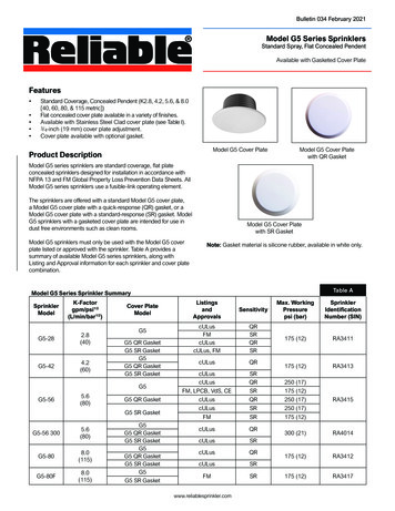
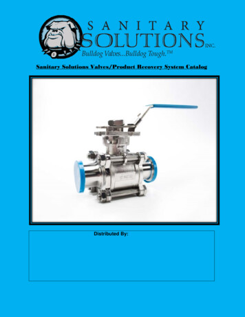
SCHEMATIC REPRESENTATION OF METALLOGRAPHIC TECHNIQUEUSED FOR EVALUATING ENVIRONMENTAL TESTS1.2.3.4.5.Metal Loss (A - B)/2Average Internal Penetration CMaximum Internal Penetration DAverage Metal Affected (A - B)/2) CMaximum Metal Affected ((A B)/2) DFABRICATION CHARACTERISTICSHEAT TREATMENTHAYNES 25 alloy is normalyfinal solution heat-treated at2150 to 2250 F (1175 to1230 C) for a time commensurated with sectionthickness. Annealing duringfabrication can be performed ateven lower temperatures, but afinal, subsequent solution heattreatment is needed to produceoptimum properties andstructure. Please call HaynesInternational for further information.EFFECT OF COLD REDUCTION UPON ROOM-TEMPERATURE ensileStrengthKsiMPa0.2% YieldStrengthKsiMPaElongationin 2 in. (51 63.0112597.967539.3RC321950 F167.1115091.263043.8RC3020(1065 C)170.7117596.566540.8RC3225for 5 1053.4RC27152050 F161.2111078.654051.9RC2820(1120 C)164.8113582.056547.6RC3125for 5 RC21152150 F156.1107573.650555.4RC2620(1175 C)154.0106072.149559.3RC2625for 5 min.149.3103068.547061.7RC25*Based upon cold reductions taken upon 0.110-inch (2.8 mm) thick sheet.Duplicate tests.15HAYNES 25 alloy
FABRICATION CHARACTERISTICSEFFECT OF COLD REDUCTION AND ANNEALING UPON GRAIN SIZE%ColdReduction0SubsequentAnnealNoneN/A1015AS TMGrain SizeRange%Recrystallization3 1/2 - 4* 101950 F7720(1065 C)9525for 5 min.10010-95- 87 1/2 - 8 10-152050 F956- 720(1120 C)1007- 825for 5 min.1007 1/2 - 81004- 4 1/2*2150 F1005- 720(1175 C)1004 1/2 - 7*25for 5 min.10041015*Some larger grains near surface.EFFECT OF SMALL COLD REDUCTIONS ON GRAIN GROWTH*%StrainInduce d**AS TMGrain SizeRangeSubsequentAnneal12- 4 1/222050 F3 1/2 - 43(1120 C)3 1/2 - 44for 5 min.3 1/2 - 58122150 F344- 5 1/22- 4 1/2Larger at SurfaceLarger at SurfaceRecrystallized at SurfaceLarger at Surface3 1/2 - 4Larger at Surface(1175 C)3 1/2 - 5 1/2Larger at Surfacefor 5 min.3 1/2 - 584 1/2 - 611- 1 1/2Larger at SurfaceLarger at Surface2250 F3(1230 C)2- 44for 5 min.2- 2 1/23- 3 1/28* Initial grain size ASTM 3 1/2 - 4 with a few larger at surface.** Samples prestrained in a tensile testing machine.16Fully Recrystallized1 1/2 - 2 1/22HAYNES 25 alloyCommentsFully Recrystallized
WELDINGHAYNES 25 alloy is readilywelded by Gas Tungsten Arc(GTAW), Gas Metal Arc(GMAW), Shielded Metal Arc(coated electrodes), electronbeam welding and resistancewelding techniques. Itswelding characteristics aresimilar to those for HAYNES188 alloy. Submerged Arcwelding is not recommendedas this process is characterized by high heat input to thebase metal and slow cooling ofthe weld. These factors canincrease weld restraint andpromote cracking.Base Metal PreparationThe joint surface and adjacentarea should be thoroughlycleaned before welding. Allgrease, oil, crayon marks,sulfur compounds and otherforeign matter should be removed. Contact with copper orcopper-bearing materials in thejoint area should be avoided. Itis preferable, but not necessary,that the alloy be in the solutionannealed condition whenwelded.Filler Metal SelectionMatching composition filler metalis recommended for joining 25alloy. For shielded metal arcwelding, HAYNES 25 alloyelectrodes (AMS 5797) areavailable. For dissimilar metaljoining of 25 alloy to nickel-,cobalt- or iron-base materials, 25alloy itself, 230-W filler wire,556 alloy, HASTELLOY S alloy(AMS 5838) or HASTELLOY Walloy (AMS 5786, 5787)welding products are suggested, depending upon theparticular case.Preheating, InterpassTemperatures and PostWeld Heat TreatmentPreheat is not usually requiredso long as base metal to bewelded is above 32 F (0 C).Interpass temperaturesgenerally should be low.Auxiliary cooling methods maybe used between weld passes,as needed, providing that suchmethods do not introducecontaminants. Post-weld heattreatment is not normallyrequired for 25 alloy. Forfurther information, pleasecontact Haynes International.HEALTH & SAFETY INFORMATIONWelding can be a safeoccupation. Those in thewelding industry, however,should be aware of thepotential hazards associated with welding fumes,gases, radiation, electricshock, heat, eye injuries,burns, etc. Also, local,municipal, state, and federalregulations (such as thoseissued by OSHA) relative towelding and cutting processes should be considered.Nickel-, cobalt-, and ironbase alloy products maycontain, in varying concentrations, the following elemental constituents: aluminum, cobalt, chromium,copper, iron, manganese,molybdenum, nickel andtungsten. For specificconcentrations of these andother elements present, referto the Material Safety DataSheets (MSDS) H3095 andH1072 for the product.Inhalation of metal dust orfumes generated fromwelding, cutting, grinding,melting, or dross handling ofthese alloys may causeadverse health effects suchas reduced lung function,nasal and mucous membrane irritation. Exposure todust or fumes which may begenerated in working withthese alloys may also causeeye irritation, skin rash andeffects on other organsystems.17The operation and maintenance of welding andcutting equipment shouldconform to the provisions ofAmerican National StandardANSI/AWS Z49.1, (Safely inWelding and Cutting).Attention is especiallycalled to Section 7 (Protection of Personnel) and 8(Health Protection andVentilation) of ANSI/AWSZ49.1. Mechanical ventilation is advisable and, undercertain conditions such as avery confined space, isnecessary during weldingor cutting operations, orboth, to prevent possibleexposure to hazardousfumes, gases, or dust thatmay occur.HAYNES 25 alloy
MACHININGOperationHigh Speed Steel ToolsCarbide Tools1Roughing, withsever interruptions;Turning orFacingM-40 series, M-2, M-33, T-4, T-8 andT-15.45 SCEA2,-10 Back Rake, 10 SideRake, 1/16" nose radius1/4" depth of cut max., 0.012" feedmax., 15 sfm cutting speedWater base coolant3C-1 or C-2 grade square insert,45 SCEA, -5 Back Rake, -5 Side Rake, 1/16" nose radius,1/4" depth of cut max.40 sfm, .012 feed max.Dry, oil, or water basecoolant6Normal roughing;Turning orFacingSame tool grades45 SCEA, 0 Back Rake, 10 SideRake, 1/16" nose radius1/4" depth of cut max., .015 feedmax.20 sfm cutting speedWater base coolantSame tool gradesSame tool geometry1/4" depth of cut max., .015feed max., 40-60 sfmdepending on rigidity ofsetup.Dry, 4,5 oil or water basecoolant6Finishing;Turning orFacingM-40 series, M-33, M-3, T-8 and T-1515-45 SCEA, 10 Back Rake, 15 Side Rake, 1/32-1/16" noseradius,.040-.010" depth of cut, .005-007"feed,25-30 sfmWater base coolantC-2 or C-3 grade square insert,if popssible15-45 SCEA, 5 Side Rake,7 5 Back Rake, 1/32-1/16"nose radius.040-.010" depth of cut, .005.007" feed, 60-90 sfmDry or water base coolant 6Rough BoringM-40 series, M-2, T-1 and T-4Same tool geometry as NormalRoughTurning with extra clearance asneeded, 1/8" depth of cut max.,.012 feed max., 15-20 sfmWater base coolantC-1 or C-2 gradeIf insert type boring bar, usestandard negative raketools with largest possibleSCEA and 1/16" nose radius.if brazed tool bar, grind 0 Back Rake, -5 Side Rake,1/16" nose radius and largestpossible SCEA, 1/8" depth ofcut max., .012 feed max.,30-50 sfm depending onrigidity of setupDry, oil or water base coolant6Finish BoringSame tool grades, geometry andcutting conditions as Finish Turningand Facing except Back Rakemay be best at 0 Water base coolantC-2 or C-3 gradeUse standard positive raketools 7 on insert type bars—grind brazed tools as forfinish turning and facingexcept back rake may bebest at 0 .50-90 sfmWater base coolantFace MillingM-2, M-7, or M-40 seriesRadial and Axial Rake 0 to 10 ,45 Corner angle, 10 Relief angle,Feed .005-.009"/tooth, 15-20 sfmOil or water base coolantCarbide not generallysuccessfulC-1 or C-2 grade may workUse negative axial and radialrake, 45 corner angle, 10 relief angle, .005-.008"/toothfeed, 30-60 sfmDry, oil base coolant or waterbase mist will reducethermal shock damage ofcarbide cutter teethHAYNES 25 alloy18
igh Speed Steel ToolsCarbide ToolsEnd MillingM-40 series or T-15If possible, use short mills with 4 ormore flutes for rigidity. For 1/2" dia.mills, feed .002"/tooth, for 1" andlarger, feed .005"/tooth, 15-20 sfmOil or water base coolantNot recommended, but C-2grades may be successfulon good setups. Feed sameas high speed steel30-60 sfmDry; oil, or water base mist willreduce thermal shockdamage.DrillingM-33, M-40 series or T-15Feed .001"/Rev 1/16" dia.002"/ Rev 1/4" dia.003"/Rev 1/2" dia.004"/Rev 1" diaUse short drills, heavy webs, 135 crankshaft grind points whereverpossible.Speed 10-15 sfmOil or water coolantUse coolant feed drills if possibleC-2 grade not recommended,but solid or tipped drills maybe successful on rigidsetups. The web must bethinned to reduce thrust.Use 135 included angle onpoint.20-40 sfmCoolant-feed carbide tippeddrills may be economical insome setups.Oil or water base coolantReamingM-33, M-40 series or T-15Use 45 corner angle, narrow primaryland and 10 relief angle,1/2" dia. feed .003"/tooth,2" dia. feed .004"/tooth,Oil or water base coolant10-20 sfmC-2 or C-3 gradeTipped reamers recommendedSolid carbide reamers requirevery good setup. Tool geometry and feed same as HighSpeed Steel 30-50 sfmTappingM-1, M-7, M-102 Flute, spiral point, plug tap 0 to 10 hook angle nitrided surface maybe helpful by increasing wearresistance but may cause chippingor breakage5 sfm cutting speed, Tap drill for 60-65%thread, if possible, to increase tool lifeUse best possible tapping compound,sulfochlorinated oil base preferred.Not recommendedNOTES:1. M-40 series High Speed Steels include M-41, M-42, M-43, M-44, M-45 and M-46 at the time of writing. Others may beadded and should be equally suitable.2. SCEA-Side cutting edge angle or lead angle of the tool.3. Water base coolant should be premium quality, sulfochlorinated water soluble oil or chemical emulsion with extremepressure additives. Dilute with water to make 15:1 mix.4. At any point where dry cutting is recommended, an air jet directed on the tool may provide substantial tool lifeincreases. A water base coolant mist may also be effective.5. Oil coolant should be a premium quality, sulfochlorinated oil with extreme pressure additives. Viscosity at 100 F from 50to 125 SSU.6. Water base coolant may cause chipping and rapid failure of carbide tools in interrupted cuts.7. Negative rake tools should be used in interrupted cuts.19HAYNES 25 alloy
STANDARD PRODUCTSBy Brand or Alloy Designation:HASTELLOY Family of Corrosion-Resistant Alloys B-2, B-3 , C-4, C-22 , C-276, C-2000 , D-205 , G-3, G-30 , G-50 and NHASTELLOY Family of Heat-Resistant AlloysS, W, and XHAYNES Family of Heat-Resistant Alloys25, R-41, 75, HR-120 , 150, HR-160 , 188, 214 , 230 , 230-W , 242 , 263, 556 , 625, 718, X-750,MULTIMET and WASPALOYCorrosion-Wear Resistant AlloyULTIMET Wear-Resistant Alloy6BHAYNES Titanium Alloy TubularTi-3Al-2.5VStandard Forms:Bar, Billet, Plate, Sheet, Strip, Coils, Seamless or Welded Pipe & Tubing, Pipe Fittings, Flanges,Fittings, Welding Wire and Coated ElectrodesProperties Data:The data and information in this publication are basedon work conducted principally by Haynes International, Inc.and occasionally supplemented by information from the openliterature, and are believed to be reliable. However, we donot make any warranty or assume any legal liability orresponsibility for its accuracy, completeness or usefulness,nor do we represent that its use would not infringe uponprivate rights. Any suggestions as to uses and applicationsfor specific alloys are opinions only and Haynes International, Inc. makes no warranty of results to be obtained inany particular situation. For specific concentrations ofelements present in a particular product and a discussion ofthe potential health effects thereof, refer to the MaterialSafety Data Sheet supplied by Haynes International, Inc.For More Information Contact:Kokomo, Indiana 46904-9013Windsor, Connecticut 06095EnglandItaly1020 W. Park AvenueP.O. Box 9013Tel: 765-456-6012800-354-0806FAX: 765-456-6905430 Hayden Station RoadTel: 860-688-7771800-426-1963FAX: 860-688-5550Haynes International, Ltd.P.O. Box 10Parkhouse StreetOpenshawManchester, M11 2ERTel: 44-161-230-7777FAX: 44-161-223-2412Haynes International, S.R.L.Viale Brianza, 820127 MilanoTel: 39-2-2614-1331FAX: 39-2-282-8273Houston, Texas 77041Anaheim, California 92806The Northwood Industrial Park12241 FM 529Tel: 713-937-7597800-231-4548FAX: 713-937-4596Stadium Plaza1520 South Sinclair StreetTel: 714-978-1775800-531-0285FAX: 714-978-1743Arcadia, Louisiana 71001-97013786 Second StreetTel: 318-263-9571800-648-8823FAX: 318-263-8088FranceHaynes International, S.A.R.L.Boite Postale 953595061 CERGY PONTOISECedexTel: 33-1-34-48-3100FAX: 33-1-30-37-8022SwitzerlandNickel Contor AGHohlstrasse 534CH-8048 ZurichTel: 41-1-434-7080FAX: 41-1-431-8787www.haynesintl.comFor Referral to Authorized Distributors in your area Fax: 1-765-456-6079Printed in U.S.A.091099
HAYNES 188 alloy, and, most recently, 230 alloy, which possess improved properties. Another area of significant usage for 25 alloy is as a bearing material, for both balls and races. Applicable Specifications HAYNES 25 alloy is covered by the following specifications: AMS 5537 (sheet, strip and plate), AMS 5759 (bar, rings and forgings), AMS 5796