Transcription
PAGE 1PIPE SIZING (COMMERCIAL) PART 2COMMERCIAL GAS PIPE SIZINGPART 2 – Using the Pressure Drop Calculator (PDC)Contents23456789101112131415Course informationAbout the PDC (version 5.2)A simple exampleThe system diagramEntering the system details into the PDCClear AllGas typeOPLeg nameUpstream typeUpstream leg nameAppliance leg?Pipe materialLengthGas rateGas rates buttonDiameterThe trial-and-error methodCalculateAdding fittingsØFinding the ‘worst-case’ appliance pressuresAdditional functions of the PDCModelling very large systemsModelling sections of a systemGas ring mainsTwin pipe systemsThe accuracy and limitations of pipe size calculationsPDC Quick Reference Guide 2021 RAD TRAINING (MIDLAND) LTD.3.2.8
PAGE 2PIPE SIZING (COMMERCIAL) PART 23.2.8Course informationThese are the user instructions for the Pressure Drop Calculator (PDC) developed byRAD Training (Midland) Ltd. for their commercial pipe sizing training course.The course includes the following optional modules:Part 1 – Pipe sizing by handHow to use the pipe sizing charts in IGEM/UP/2 in a fully-developed pressure lossallocation methodPart 2 – Pipe sizing using an appHow to use the Pressure Drop Calculator (PDC)Part 3 – Pipe sizing extensions to a systemHow to determine the feasibility of adding new extensions to existing systemsPart 4 – Theory of fluid flowHow to make your own pipe sizing charts: a deeper look at the physics andmathematics of gas flow through pipesContact informationFor more information about the course and how to obtain a copy of the PDC, pleasevisit www.radmidlands.co.uk or email r-price@btconnect.com 2021 RAD TRAINING (MIDLAND) LTD.
PAGE 3PIPE SIZING (COMMERCIAL) PART 23.2.8About the PDC (version 5.2)The PDC spreadsheet runs in Microsoft Excel. These notes assume the user has a basicworking familiarity with Excel.Please note that you may have to click Enable Content and/or Enable Macros etc. touse the PDC, depending on the security settings of your computer.The PDC calculates steady-state working pressure losses in steel, PE and copperpipework for low pressure, medium pressure and high pressure natural gas (NG) andLPG (propane) systems.The PDC can: Model systems or sections of up to 58 pipe legsAutomatically handle additional equivalent lengths of many types of fittingCalculate gas flow rates through pipe legsGive user warnings if the gas speed in any pipe exceeds 20 m / sCalculate installation volume (IV) of pipework and fittingsHandle a single-loop gas ring mainHandle one twin (parallel) pipe legPressure loss calculations are always approximate. Many real-world variables includingpipe condition, nominal diameter vs internal diameter, quality of jointing etc. have alarge effect. Use tolerances which overestimate pressure losses. Double-check allentered data. Confirmation of results using different methods is recommended, as isseeking expert advice for major projects. 2021 RAD TRAINING (MIDLAND) LTD.
PAGE 4PIPE SIZING (COMMERCIAL) PART 23.2.8A simple exampleSteel pipework is required to supply a natural gas appliance of 175 kW net heat input.The system operating pressure is 21 mbar. Pipe length from meter to appliance is 45 m.What diameter of pipe will be needed?We will use the PDC to find the smallest steel pipe diameter that will give a pressuredrop no greater than 1 mbar from the meter outlet to the appliance connection. Load the PDC and click Clear AllSelect Gas Type as NGEnter OP as 21Enter Leg name as A (or any other name you want)Select Upstream type as MeterSelect Appliance Leg? as YesSelect Pipe material as SteelEnter Length as 45Leave Fittings blank (for simplicity we ignore fittings in this example)Enter Gas rate as 18.4 (this is 175 kW divided by the conversion 9.5 to obtaingas rate in m3 / h). You could also enter this as 175 / 9.5 where the equals signlets Excel know you want it to evaluate the expression.We now enter trial diameters, starting with the smallest we think may do the job andworking up in size until we get a pressure loss of 1 mbar or less.Start by entering 32 into Diameter. Click Calculate. Pressure loss to the end of leg A(ΔPTOTAL) comes to more than 6 mbar:Change Diameter to 40 and click Calculate again. ΔPTOTAL is still over 2 mbar.Try 50. Pressure loss falls under 1 mbar.50 mm steel is therefore the smallest size of steel that will work. 2021 RAD TRAINING (MIDLAND) LTD.
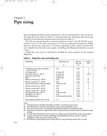
PAGE 5PIPE SIZING (COMMERCIAL) PART 23.2.8The system diagramIn any complex pipe sizing problem, it is essential to start with a good diagram. Thediagram should show: Fuel gas typeOperating pressure (OP) in mbarAll pipe legs (pipe sections between meters, tees, reducers and appliances)Pipe leg lengths in metresPipe fittings (tees, elbows, bends and valves)Gas rates of all appliances (preferably in cubic metres per hour)The diagram below shows a proposed system which we will use as a worked example.STEEL PIPE SYSTEM DIAGRAM – ADR PHARMACEUTICALS LTD.NAT. GAS OP 21 mbar14.8m3 / hH 16melbowisolation valve (AIVs not shown)A 34mE 51mG 32mI 10mB 16mMeter22.5m3 / hC6mD7mF 22m17.3m3 / h5.8m3 / h64.6m3 / hNote: the common node-based method of naming legs (A-B, B-C, B-D etc.) should notbe used in the PDC. Instead, simply give each leg a unique name such as A, B, C,Boiler 3 etc. This has the advantage of reducing visual clutter – and needs one fewerletter to describe a system! 2021 RAD TRAINING (MIDLAND) LTD.
PAGE 6PIPE SIZING (COMMERCIAL) PART 23.2.8Entering the system details into the PDCClick Clear All to ensure no previous calculations remain. Select Gas type as NG(natural gas) and enter OP (operating pressure in mbar) as 21. Enter Leg name for eachleg in order of gas flow (A, B, C, D, E, ). The first leg name is lilac-shaded to indicatethat it connects to the pressure source. Note: whenever entering L as a leg name,check that Excel does not auto-complete the cell with Leg name! We recommendturning off auto-complete when using the PDC.Select the Upstream type for each leg. The PDC follows the conventions of IGEM/UP/2in distinguishing between three configurations of tee:Gas flowThrough teeTee from branch(Type 2 fitting)added to this legGas flow(Type 4 fitting)added to these legsTee into branch(Type 5 fitting)added to this legUpstream types in the example are: AMeter BTee into branch C, D Tee from branch EThrough tee FGH, ITee into branchThrough teeTee from branchNote that H and I aren’t actually from a branch – they’re from the main run – but theirconfiguration is obviously the same as the tee connecting legs C and D.Enter Upstream leg name for each leg so that the PDC knows how the system isconnected. The first leg is always set to OP, i.e. the available incoming pressure.In the Upstream leg name of leg B, type a capital letter A. Always type Upstream legname so it exactly matches the actual name. Press the down arrow key to move to legC. Leg C gets its gas from leg B, so type B and press the down arrow key. Leg D alsogets its gas from leg B, so enter B again and press the down arrow key. Continue untilall legs have been connected correctly. 2021 RAD TRAINING (MIDLAND) LTD.
PAGE 7PIPE SIZING (COMMERCIAL) PART 23.2.8Select Appliance leg? as Yes for legs C, D, F, H and I only. Certain cells are thenhighlighted in blue because these values have special significance for appliances.Note: the Isolated option in the drop-down list allows you to temporarily remove anappliance from calculations. To reinstate the appliance, select Yes from the list.Select the Pipe material of each leg. In this example, all pipe legs are steel. You can usecut-and-paste to speed up data entry. Select leg A as Steel, then press CTRL-C to copy.Select cells E9 to E16 and press CTRL-V to paste Steel into all the other legs.Note: choosing Pipe material as Other causes the PDC to use a high friction factor.This can be useful for modelling pipework in poor condition, e.g. rusted pipework.Enter the Length of each leg in metres. Note: only enter numerical data, not the unit ofmeasurement; i.e. do not enter ‘m’ for metres after the number.We will skip entering details of fittings for the moment.Enter the Gas rate (in m3 / h) of all legs which connect directly onto appliances, i.e. legsC, D, F, H and I only. To find gas rates in other legs, click the Gas Rates button.For Diameter (internal diameter in millimetres), enter initial guesses as follows:A65F25B40G50C25H25D25I25E65Note 1: PE pipe is specified by its outside diameter (OD). If SDR (Standard DimensionRatio) is known, the following formula can be used to find internal diameter (ID):𝐼𝐷 𝑂𝐷 2 𝑂𝐷𝑆𝐷𝑅For example, 63 mm SDR 11 PE pipe, diameter can be entered as 63 – 2*63/11Note 2: copper pipe is specified by its outside diameter. Internal diameter will need tobe obtained from the manufacturer. 2021 RAD TRAINING (MIDLAND) LTD.
PAGE 8PIPE SIZING (COMMERCIAL) PART 23.2.8The trial-and-error methodThe PDC now has enough information to calculate pressure losses in the system.Click the Calculate button.We immediately get warning of high gas speed followed by a Pressure Loss Error onleg F. The PDC informs us that working pressure has fallen to zero. This is because theinitial guess diameters are far too small. We will now use the PDC to find the correctdiameters.Click OK to clear the errors. Change the diameter of leg A to 80. Click Calculate. Thishas improved things a little but the PDC is still giving an error. Changing A to 100further improves pressure loss across leg A but downstream legs are still too small.Try changing the diameters of:B to 65C and D to 50E to 100F and G to 65H and I to 40Re-calculate. The situation has improved so that there is no error, but pressure lossesto appliances are still more than 1 mbar (these are shown in the PTOTAL column, whichis shaded blue for appliance legs).We observe that the combined loss of legs A and E is over 1 mbar. We make thedecision to increase leg A to 125. Appliances C and D now have a drop just below1 mbar but remember we are yet to add fittings.Changing E to 125, F to 80 and G to 100 brings the pressure loss to appliances F and Ito under a millibar but appliance H is still over. Changing H to 50 corrects this.This example gives a good idea of the trial-and-error method that can be employedusing the PDC. The better the initial guesses, the easier this process will be. 2021 RAD TRAINING (MIDLAND) LTD.
PAGE 9PIPE SIZING (COMMERCIAL) PART 23.2.8Adding fittingsThe PDC automatically (and implicitly) adds additional length for the following fittings: Meter outlet valve (MOV)Tees (all configurations)Appliance isolation valvesReducers (and expanders)Isolation valves for branches 50 mm diameter (NG) or 30 mm (LPG)In this example, we only need to manually add elbows. (Branches B and F are now sizedat 50 mm or more, so the PDC automatically adds branch isolation valves). Enter 2 x 90º elbows (Type 3 fittings) to A, 2 to E, and 1 to HClicking Calculate shows that appliance C now has a pressure loss slightly over 1 mbar.Sometimes, a pressure loss may exceed the permitted limit by an amount smaller thanuncertainties in measurements or in calculations. In such cases a decision may be madeto accept the pipe sizes as they are.Note: the Ø column shows the largest connection diameter of tees and reducers.According to IGEM/UP/2, additional length for branch tees must be based on thediameter of their largest connection. The PDC determines Ø automatically exceptwhere there is a tee or reducer upstream of the first leg. This happens when a sectionof a larger system is being modelled (see page 11). In such situations, the PDC willrequest that you enter Ø manually for the first leg.Finding the ‘worst-case’ appliance pressuresTo see worst-case appliance inlet working pressures, change OP to the lowestexpected available pressure and re-calculate. For example, on a standard UK naturalgas supply of 21 mbar, tolerance is 2 mbar. Set OP to 19 and re-calculate. Note: inletworking pressures are shown in the POUT column of appliance legs. 2021 RAD TRAINING (MIDLAND) LTD.
PAGE 10PIPE SIZING (COMMERCIAL) PART 23.2.8Additional functions of the PDCClear Row – completely clears all cells on the selected rowClear Calcs – clears all PDC calculations, leaving user-entered data untouchedInsert Row – inserts a new blank row above the selected rowInsert Row is used to split a leg in order to add a new branch, insert a reducer etc. Forthe system in the worked example, in order to add a new branch J halfway along leg A:JA1 A2Click on any selectable cell in leg B and click Insert RowIn the new row, enter Leg name: A2, Upstream type: Through tee, Upstreamleg name: A1, Pipe material: Steel, Length: 17, Diameter: 125For leg A, change Leg name to A1 and Length to 17For legs B and E, change Upstream leg name to A2Below Leg I, enter the details of new branch J (Upstream leg name: A1)Remove Row – removes the selected row, shifting other rows up to fill the gapNote: you will have to manually amend the Upstream Row of any leg immediatelydownstream of the deleted leg.Show IV – calculates the IV of the pipework (with an additional 10 % for fittings) 2021 RAD TRAINING (MIDLAND) LTD.
PAGE 11PIPE SIZING (COMMERCIAL) PART 23.2.8Modelling very large systemsIf a system consists of several discrete sections, each containing banks of appliances, itcan be modelled over multiple copies of the PDC: one for the main pipework and onefor each appliance bank. For the main system, enter each bank as a single appliance withgas rate equal to the total of the appliances in that bank.36 13.5 m /hboiler banksH2H4FCDH1H3BEAMeterLegs H1, H2, H3 and H4 are entered with Appliance Leg? set to Yes and Gas rate: 81(because 6 13.5 81 m3 / h). POUT of legs A, C, E and F should be noted and used asOP when the respective banks are modelled. You should also note how much pressureremains for each bank (subtract ΔPTOTAL of legs A, C, E and F from the maximumallowed pressure drop for
PAGE 4 PIPE SIZING (COMMERCIAL) PART 2 3.2.8 2021 RAD TRAINING (MIDLAND) LTD. A simple example Steel pipework is required to supply a natural gas appliance of 175 kW net heat input. The system operating pressure is 21 mbar. Pipe length from meter to appliance is 45 m. What diameter of pipe will be needed?File Size: 378KBPage Count: 12

