Transcription
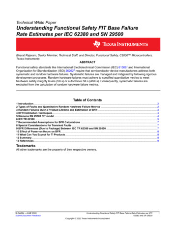
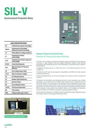
SIL-VSynchrocheck Protection RelayANSI CODE PROTECTIONS59Instantaneous phase overvoltage59N/GInstantaneous Calculated/Measured neutral overvoltage47Phase Balance voltage protection27Instantaneous Phaseundervoltage27V1Instantaneous Positive e of change of Frequency(ROCOF)78Out of Step (Vector Shift) V/ tRate of change of voltage79AC Reclosing device52Breaker Wear Monitoring25Synchro CheckBFCircuit Breaker Failure74TCSTrip Circuit Supervision86Trip LockoutPGCProgrammable logic controlAdditional information to fault reports84Voltage & Frequency Protection RelayProtection for Primary and Secondary Distribution The SIL-V is a voltage and frequency protection relay for transformers and electricalmachines, in high, medium, and low voltage distribution systems. Also protectsdecoupling, load shedding and loss of main (islanding), with auxiliary power supply of24-230 Vdc/ac. Capability of measuring up to 1.000 volts when it is connected directly to the lowvoltage line. Metallic box with high electromagnetic compatibility level (EMC) and wide range ofoperating temperature. Direct signalling/control of the circuit breaker (52 function) and the recloser (79function). Protection of decoupling, load shedding and loss of main (islanding). Loss of Main(islanding) occurs when part of the public utility network loses connection with therest of the system. If this situation is not detected, then the generator could remainconnected, causing a safety hazard within the network. Automatic reconnection of thegenerator to the network may occur causing damage to the generator and the network.SIL-G protection relay detects this situation thanks to its voltage and frequencyfunctions focused on the Rate of change of frequency (ROCOF) method. Zone selection interlocking - ZSI (68 function) is available through configurable inputsand outputs thanks to the programmable logic (PGC).
To allow the communication, relays are provided with a local RS232front port and with remote communication with different options (portsand protocols) on the rear side:to 200 events and disturbance fault recording (DFR - 20 fault reportsand 5 oscillographic records in COMTRADE format), maintaining date& time thanks to its internal RTC (real Time Clock). 1 RS485 Port: IEC60870-5-103, Modbus RTU orDNP3.0 Serial (depending on model selectable bygeneral settings). 1 RJ45 Port: IEC61850, Modbus TCP/IP, DNP3.0TCP/IP or IEC60870-5-104 (depending on model). The oscillography is downloaded by communications port. TheSICom communications program allows the oscillography record tobe downloaded and saved in COMTRADE format (IEEE C37.1111991). The SIL-V has 6 configurable inputs and 4 configurable outputs. SIL-V is provided with non-volatile RAM memory in order to store upOPENU lity networkInterconnected P sysQ syssystemP loadQ loadP genQ genGeneratornetwork85
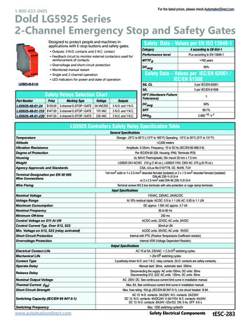
Functions diagram SIL-VEvents (200)RTCOscillography (5X2SG)Fault report (20)Setting table (3 )Leds config. (8)Inputs config. (8)Out config. (4)BFPLCTest menuHmi: LCD 20X2 10 Keys86525252797974TCS74TCS594759N2727V181O81U81RV/ TBF25*7825IEC 61850*IEC 60870-5-104*ModBus*DNP3.0*IEC 60870-5-103* RTU* optionalModBus RTU.Tx, RxRS232SICom86
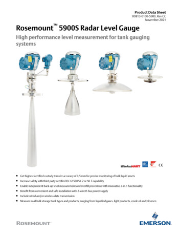
Dimensions and cutout SIL-V87
Technical parameters SIL-VFunction enable: Yes/NoFunction enable: Yes/NoVoltage tap: 3 to 555 V (step 0.1 V)Type: Underfrequency or overfrecuencyTime delay: 0.02 to 300.00 s (step 0.01 s)Operating range: 45.00 a 65.00 Hz (step 0.01 Hz)Function 27-1Reset time: 0.02 to 300.00 s (step 0.01 s)Operating time: 0.06 a 300 s (step 0.01 s)Function 27-2Activation level: 100%Deactivation level: 105%Function 81-1Temporized deactivationFunction 81-2Timing accuracy: 0.5% or 30 ms (greater of both)Function 81-3Function enable: Yes/NoVoltage tap: 3 to 555 V (step 0.1 V)Function 81-4Temporized deactivationFunction enable: Yes/NoTiming accuracy: 0.5% or 30 ms (greater of both)Type: Increment or DecrementFunction enable: Yes/NoLevel: 0.1 to 5 Hz/s (step 0.1 Hz/s)Voltage tap: 6 to 999 V (step 0.1 V)Operating time: 0.06 to 40 s (step 0.01 s)Reset time: 0.02 to 300.00 s (step 0.01 s)Function 59-2Activation level: 100%Function 81R-1Function 81R-2Deactivation level: 95%Function enable: Yes/NoVoltage tap: 6 to 999 V (step 0.1 V)Time delay: 0.02 to 300.00 s (step 0.01 s)Activation level: 100%Deactivation level: 95%Deactivation level: 90%Function enable: Yes/NoFunction 78-1Function 78-2Level: 1 to 25. (step 1 )Reset time: 0.02 to 300 s (step 0.01 s)Level accuracy: 0.5 Temporized deactivationTiming accuracy: 0.5% or 30 ms (greater of both)Blocked function if phase b voltage is lower than45 voltsFunction enable: Yes/NoFunction enable: Yes/NoVoltage tap: 6 to 999 V (step 0.1 V)Hold enable: Yes/NoTime delay: 0.02 to 300.00 s (step 0.01 s)Number of recloses: 1 to 5 (step 1)Reset time: 0.02 to 300.00 s (step 0.01 s)Activation level: 100%Function ΔV/ΔtActivation level: 100%The frequency measurement is an average valueof the frequency measured during 8 cycles. Theoperating time will be the adjusted value plus amaximum of 160 ms (50Hz) or 133 ms (60 Hz)corresponding to the necessary 8 cycles to achievethe frequency measurement.Timing accuracy: 0.5% or 30 ms (greater of both)Reset time: 0.02 to 300.00 s (step 0.01 s)Reset level: 0.06 to 40 s (step 0.01 s)Blocked function if phase b voltage is lower than45 voltsTemporized deactivationFunction 47Temporized deactivationDeactivation level: 105%Activation level: 100%Function 59-1Function 59N/G-2Underfrequency reset level: 50mHzOverfrequency reset level: -50 mHzThe frequency measurement is an average valueof the frequency measured during 8 cycles. Theoperating time will be the adjusted value plus amaximum of 160 ms (50Hz) or 133 ms (60 Hz)corresponding to the necessary 8 cycles to achievethe frequency measurement.Reset time: 0.02 to 300.00 s (step 0.01 s)Time delay: 0.02 to 300.00 s (step 0.01 s)Function 59N/G-1Blocked function if phase b voltage is lower than45 voltsActivation level: 100%Time delay: 0.02 to 300.00 s (step 0.01 s)Function 27V1Reset time: 0.02 a 300 s (step 0.01 s)Reclosing time: 0.02 to 300.00 s (step 0.01 s)Function 79Hold time: 0.02 to 300.00 s (step 0.01 s)Deactivation level: 95%Reset time: 0.02 to 300.00 s (step 0.01 s)Timing accuracy: 0.5% or 30 ms (greater of both)Definitive opening Time: 0.02 to 300.00 s (step 0.01s)Function enable: Yes/NoLocking possibilities: pulse inputs, level inputs,commands.Type: Increment or DecrementActivation level: 1 to 200 V/s (step 1 V/s)Maximum number of openings: 1 to 10000 (step 1)Operating time: 1.00 to 40.00 s (step 0.01 s)Maximum number of repetitive openings: 1 to 10000(step 1)Reset time: 0.02 to 300 s (step 0.01 s)Timing accuracy: 60 ms or 5% (greater of both).Function 52Time of repetitive openings: 1 to 300 min (step 1min)Maximum opening time 0.02 to 30.00 s (step 0.01 s)Maximum closing time 0.02 to 30.00 s (step 0.01 s)Function enable: Yes/NoFunction 74TCSTime delay: 0.02 to 300.00 s (step 0.01 s)Continuity in circuits A and BFunction start: configurable by the user88
Technical parameters SIL-VFunction enable: Yes/NoFunction BFStarting from phase B line voltage, passing throughzero detection to line frequencyStarting from phase B busbar voltage, passingthrough zero detection to busbar frequency.Time delay: 0.02 to 1.00 s (step 0.01 s)Function start: configurable by the userDead voltage level: 3 to 555 V (step 0.1 V)Live voltage level: 6 to 999 V (step 0.1 V)Function 25 (*)Line Phase B frequencyFrequencymeasurementsVoltage supervision time: 0.02 to 300 s (step 0.01 s)Busbar phase B frequency (*)Line-Bar voltage difference:4 to 50 V (step 0.1 V)Busbar and line frequency difference (*)Line-Bar phase difference: 2 to 90 (step 0.1 )Minimum voltage (to achieve the measurement): 40VLine-Bar frequency difference: 0.06 to 10 Hz (step0.01 Hz)Accuracy: 0.01 HzLocal port (RS232 DB9): Modbus RTUSynchronism Time: 0.02 to 300 s (step 0.01 s)Phase B line voltage and busbar voltage. Modulesand phases using DFTFrequency using hardware circuit with the passingthrough zero detection.CommunicationsPermission signal minimum time 150 msPower supplyFunction 49TAvailable through configurable inputs thanks to theprogrammable logicFunction 86Allows to latch (lock out) the contact trip due toprogrammable logic (PLC: OR LATCH).Programmable logiccontrol (PGC)OR4, OR4 LATCH, OR4 PULSES, OR4 TIMERUP,OR4 PULSE,NOR4,NOR4 LATCH,NOR4TIMERUP, NOR4 PULSE, AND4, AND4 PULSES,AND4 TIMERUP, AND4 PULSE, NAND4, NAND4TIMERUP, NAND4 PULSESettings GroupsSequential EventsRecording (SER)3 settings groupsSelectable by input or general setting200 events16 samples/cycleFault start configurableDisturbance faultrecording (DFR)Frequency derivative respect to the time1 remote port with the following options- 1 Remote port RS485: ModBus RTU or IEC 608705-103 (*)- 1 Remote port RJ45: IEC 61850, DNP3.0 TCP/IP orIEC 60870-5-104 (*)24-230 Vdc / Vac-20%/ 10%Operating temperature: -10 to 70ºCEnvironmentalconditionsStorage temperature: -20 to 80 ºCRelative humidity: 95%VT connectionPhase-Neutral/Phase-Neutral VrPhase-Phase/Phase-Phase VrMetallic boxPanel mountedMechanicalcharacteristicsHeight x Width: 177 x 107 (mm)Depth: 122.1 mmIP-54Weight: 1,5 kg(*) Optional depending on model20 fault reports with 24 events each one5 COMTRADE records (88 cycles): 3 pre-fault cycles 85 postfault cycles.COMTRADE IEEE C37.111-1991InputsOutputs6 configurable inputs.The voltage of the inputs is the same as the auxiliarypower supply4 Configurable outputs250 V AC – 8 A30 V DC – 5 AOutput 1 and Output 2: NC - NOOutput 3 and Output 4: NOFrequencyVoltagemeasurements50/60HzPhase voltages (V-A, V-B, V-C), calculated neutralvoltage (3V-0), residual voltage (V-R) (*), Busbarvoltage (V-BB) (*), positive sequence voltage (V-1),negative sequence voltage (V-2), maximum voltage(Vmax) and minimum voltage (Vmin)Measurement range:Low scale (rated voltage 250 V) 3-250VHigh scale (ratedvoltage 250V) 12-1000 V89
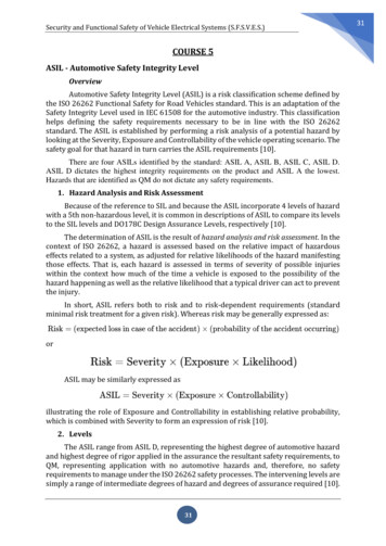
Connections diagram SIL-V3 VT Configuration (phase-neutral) residual voltage90
Connections diagram SIL-V2VT Configuration (phase-phase) residual voltage91
Connections diagram SIL-V3 VT Configuration (phase-neutral) busbar voltage(Model with Syncrhonism)92
Connections diagram SIL-V3 VT Configuration (phase-phase) residual voltage93
Connections diagram SIL-VConnecting the relay directly to Low Voltage linePhase to neutral configuration (250-480 V)94
Selection & Ordering data SIL-VVoltage & Frequency Protection /Synchronism Check RelaySIL-VPHASE MEASUREMENTDefined by General Settings0NEUTRAL MEASUREMENT0Defined by General SettingsNET FREQUENCY0Defined by SettingsPOWER SUPPLYC24-230 Vac/dcADDITIONAL FUNCTIONS0-2 25REMOTE COMMUNICATIONSARS232 (Modbus RTU) RS485 (Modbus RTU orIEC60870-5-103)BRS232 (Modbus RTU) RJ45 (IEC 61850)CRS232 (Modbus RTU) RJ45 (DNP3.0 TCP/IP)DRS232 (Modbus RTU) RJ45 (IEC 60870-5-104)INPUTS AND OUTPUTS16 Inputs 4 outputsMECHANICAL ASSEMBLY2Vertical AssemblyLANGUAGEAEnglish, Spanish and GermanBEnglish, Spanish and TurkishCEnglish, Spanish and FrenchEEnglish, Spanish and RussianADAPTATIONA27(2) 27V1 59(2) 47 59N/G(2) V/ T 74TCS BF 52 79 81U/O(4) 81R(2) 78 86Example of ordering code:SIL-V000C2A12BASIL V 0 0 0 C 2 A 1 2 B A95
Voltage & Frequency Protection Relay Protection for Primary and Secondary Distribution The SIL-V is a voltage and frequency protection relay for transformers and electrical machines, in high, medium, and low voltage distribution systems. . Function 59N/G-1 Function 59N/G-2 Function enable: Yes/No Voltage tap: 6 to 999 V (step 0.1 V) Time .