Transcription
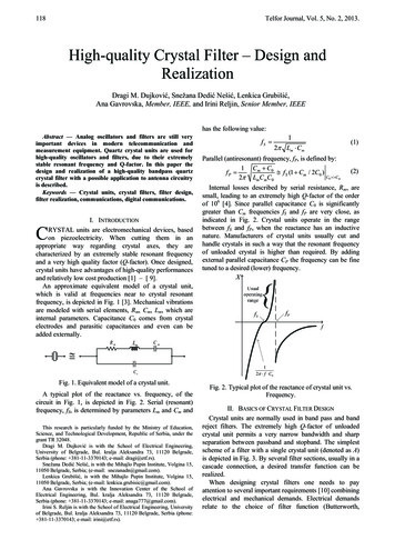
118Telfor Journal, Vol. 5, No. 2, 2013.High-quality Crystal Filter – Design andRealizationDragi M. Dujković, Snežana Dedić Nešić, Lenkica Grubišić,Ana Gavrovska, Member, IEEE, and Irini Reljin, Senior Member, IEEEhas the following value:1 Abstract — Analog oscillators and filters are still veryimportant devices in modern telecommunication andmeasurement equipment. Quartz crystal units are used forhigh-quality oscillators and filters, due to their extremelystable resonant frequency and Q-factor. In this paper thedesign and realization of a high-quality bandpass quartzcrystal filter with a possible application to antenna circuitryis described.Keywords — Crystal units, crystal filters, filter design,filter realization, communications, digital communications.I. INTRODUCTIONRYSTAL units are electromechanical devices, basedon piezoelectricity. When cutting them in anappropriate way regarding crystal axes, they arecharacterized by an extremely stable resonant frequencyand a very high quality factor (Q-factor). Once designed,crystal units have advantages of high-quality performancesand relatively low cost production [1] – [ 9].An approximate equivalent model of a crystal unit,which is valid at frequencies near to crystal resonantfrequency, is depicted in Fig. 1 [3]. Mechanical vibrationsare modeled with serial elements, Rm, Cm, Lm, which areinternal parameters. Capacitance C0 comes from crystalelectrodes and parasitic capacitances and even can beadded externally.CRmLmfS 1(1)2 Lm CmParallel (antiresonant) frequency, fP, is defined by:1 C m C0fP f S (1 Cm / 2C0 )C0 Cm2 Lm Cm C0(2)Internal losses described by serial resistance, Rm, aresmall, leading to an extremely high Q-factor of the orderof 106 [4]. Since parallel capacitance C0 is significantlygreater than Cm frequencies fS and fP are very close, asindicated in Fig. 2. Crystal units operate in the rangebetween fS and fP, when the reactance has an inductivenature. Manufacturers of crystal units usually cut andhandle crystals in such a way that the resonant frequencyof unloaded crystal is higher than required. By addingexternal parallel capacitance CP the frequency can be finetuned to a desired (lower) frequency.X{fSfPfCm CoFig. 1. Equivalent model of a crystal unit.A typical plot of the reactance vs. frequency, of thecircuit in Fig. 1, is depicted in Fig. 2. Serial (resonant)frequency, fS, is determined by parameters Lm and Cm andThis research is particularly funded by the Ministry of Education,Science, and Technological Development, Republic of Serbia, under thegrant TR 32048.Dragi M. Dujković is with the School of Electrical Engineering,University of Belgrade, Bul. kralja Aleksandra 73, 11120 Belgrade,Serbia (phone: 381-11-3370143; e-mail: dragi@etf.rs).Snežana Dedić Nešić, is with the Mihajlo Pupin Institute, Volgina 15,11050 Belgrade, Serbia; (e-mail: snezanadn@gmail.com).Lenkica Grubišić, is with the Mihajlo Pupin Institute, Volgina 15,11050 Belgrade, Serbia; (e-mail: lenkica.grubisic@gmail.com).Ana Gavrovska is with the Innovation Center of the School ofElectrical Engineering, Bul. kralja Aleksandra 73, 11120 Belgrade,Serbia (phone: 381-11-3370143; e-mail: anaga777@gmail.com).Irini S. Reljin is with the School of Electrical Engineering, Universityof Belgrade, Bul. kralja Aleksandra 73, 11120 Belgrade, Serbia (phone: 381-11-3370143; e-mail: irini@etf.rs).12 f C0Fig. 2. Typical plot of the reactance of crystal unit vs.Frequency.II. BASICS OF CRYSTAL FILTER DESIGNCrystal units are normally used in band pass and bandreject filters. The extremely high Q-factor of unloadedcrystal unit permits a very narrow bandwidth and sharpseparation between passband and stopband. The simplestscheme of a filter with a single crystal unit (denoted as A)is depicted in Fig. 3. By several filter sections, usually in acascade connection, a desired transfer function can berealized.When designing crystal filters one needs to payattention to several important requirements [10] combiningelectrical and mechanical demands. Electrical demandsrelate to the choice of filter function (Butterworth,
Dujković et al.: High-quality Crystal Filter – Design and RealizationR inC1AC2R outFig. 3. Basic filter section realized withsingle crystal unit.Chebyshev, etc.) and the filter order for satisfying givenspecifications: required attenuation limits in passband(max attenuation) and stopband (min attenuation),permitted ripple in the passband, lowest and highestfrequencies in the passband (or stopband) region, thewidth of transition regions, phase and delay requirements,etc. Also, input and output resistances (impedances)should be matched with the source and the load, forsatisfying VSWR or return loss requirements.Regarding mechanical demands, note that crystal unitsare electromechanical devices with a precise (mechanical)resonant frequency. Due to that they are very sensitive toexternal vibrations and shocks, so special attention shouldbe addressed to the mounting and housing. Also, someinterharmonical modes of vibrations may occur producing“spurious” responses – very narrow responses, generallylocated at high frequencies, which considerably differfrom desired values. If they appear in the stopband, theattenuation is decreased, while in the passband they willintroduce an unwanted notch. Fortunately, spuriousresponses are very narrow and they usually don’t cause aserious problem unless for signals at just thesefrequencies.Additional requirements may be addressed toenvironmental conditions, such as temperature range,humidity, etc., in which the crystal filter has to operate.The number of crystal units is dictated by a desired filterorder, because each crystal unit is characterized by onecomplex pole (see Fig. 2). Therefore, the filter with Ncrystals is often referred to as a filter with N poles.Parallel capacitances, denoted as C0 in Fig. 1, reduce thebandwidth, but this effect can be minimized by addinglow-loss parallel inductances. By adding serialcapacitances between crystal units their coupling andimpedance matching can be obtained.Actually, there are only a few global manufacturers thatoffer the possibility of crystal filters realization en,manufacturers produce standard (typical) crystal units andfilter types.By following previous theoretical considerations [11]and rich professional experience of researchers at theSchool of Electrical Engineering and the Institute MihajloPupin in Belgrade [12] – [15], we have derived aprocedure for the design and realization of the high-qualitycrystal filter QFA2106, which will be described in the followingsections.III. REQUIREMENTS FOR FILTER QFA2106A band-pass filter QFA2106, suitable for a highfrequency range [1] – [10] (as in antenna circuits), wasdesigned and realized, according to strict requirements that119meet the specifications for basic and special conditions,which are set by the customer.One of the important demands was to achieve as high aspossible attenuation in the stop-band, and to reducespurious responses in the range of interest. Regarding thedesired attenuation, an appropriate filter order (the numberof crystal units) was determined, while the reduction ofspurious responses was obtained by choosing the optimaldiameter of the crystal unit [2] and by an appropriatearrangement of components on the printed circuit board.The filter central frequency of 126.95 MHz in thepassband provides relative attenuation smaller than 3 dB inthe frequency range of 7.5 kHz and attenuation greaterthan 40 dB outside the band of 40 kHz. In the rangewithin 50 kHz, the relative decline is more than 40 dB.In Table I, we present technical characteristics of theproposed filter QFA2106, required by our customer.Minimal transducer attenuation in the passband shouldbe less than 6dB. Input and output filter impedances are50Ω. Operating temperature range is -20 ºC to 70 ºC,while storage temperature range is -40 ºC to 85 ºC. Thefilter should be placed in the housing G10 BNC of the size61x26x2 (dimensions in mm).The manufacturing process applied to filters QFA2106can be used for the production of all the types of crystalfilters, which have strict requirements regarding the levelof guaranteed attenuation in the stopband and strictlydefined ripple and phase characteristic of the passband.TABLE 1: REQUIRED TECHNICAL CHARACTERISTICSOF THE FILTER QFA210.ParameterReference frequencyBandwidth at 3 dBPass band rippleTransition band to attn. 20dBTransition band to attn. 40dBRelative attenuation (min)Min. transducer attenuationInput impedanceOutput impedanceValues of spurious responsesOperating temperature rangeStorage temperature rangeMaximum drive levelHousingValue126.95 MHz 7.5 kHz min1 dB max 30 kHz max 60 kHz max40 dB6 dB max50 Ω50 Ω10 dB max-20 ºC to 70 ºC-40 ºC to 85 ºC 10 dBmG10 BNCIV. DESIGN OF THE CRYSTAL FILTER QFA2106The whole filter design has been performed through twobasic parts: the circuit design and design of crystal units.Circuit design relates to electrical requirements(approximation function, filter order, the number of crystalunits, etc.), after that particular design of crystal units isperformed. Both designing parts are mutually dependent insome way and design process should be derived throughseveral iterations, which needs high designers’ experience.
120Telfor Journal, Vol. 5, No. 2, 2013.A. Circuit designThe circuit is designed by using transformationtechniques for the cascade of lattice sections. The transferfunction and filter topology are determined according tospecified requirements.Based on the specifications of the amplitude response instop- and pass-band, the approximation function, filterorder and corresponding filter topology are determined(Fig. 4). The circuit is designed under the assumption ofreal (non-ideal) filter elements. Circuit design defines therequirements for the crystal unit [1], [7], [9], [11]. As anassistant tool for testing filter design we used computerprogram developed for such purposes [15].The filter order determines the number of crystalsrequired. As depicted in Fig. 4, the filter is composed offour quartz resonators in a semi-lattice network, with twotypes of crystal units, denoted as A and B. The choice ofcrystal unit has a major impact on the overall filterperformances. For instance, inappropriate choice of crystalunit may produce high spurious response, then, unitshaving a low Q-factor may degrade amplitude and/orphase response, etc. After determining filter order andtopology, the next step is to choose crystal units (usuallycalled crystal resonators) having parameters which arewell suited to given requirements.R inCTAACTVinL1C1C1L2C1BC2L1VoutRoutC1Bare plan-parael (PP) with a diameter of Φ 5mm in a coldwelded (CW) housing (HC-45 type). For assuring highrejection of spurious responses, extremely high planparallelism of crystal plates is necessary [11] – [14]. Thisis a very challenging technology problem and only a fewmanufacturers in the global market can resolve it.TABLE 2: REQUIRED TECHNICAL CHARACTERISTICS FORCRYSTAL UNITS USED IN FILTER QFA2106.ItemHousingCrystal unit frequencyQ-factorDynamic capacityParallel capacityDynamic resistanceFrequency adjustmentFrequency toleranceAgingSpurious frequencies (fn)Operating temperaturerangeStorage temperature rangeValueHC-45fA 126938.830kHzfB 126961.160kHz 60,000Cm 0.083 mpF 10%C0 0.9 pF 5%R1 190Ώdf/f 10ppmdf/f 15ppmdf/f 1ppm/yrA. f0 80kHz, without fnB. fn 35dB, f0 1MHz-20 ºC to 70 ºC-40 ºC to 85 ºCNotes: Frequencies fA and fB are crystal unit frequencies(unit A and B). Both units have the same Q-factor.Capacitance Cm, C0 and resistance R1 are from theequivalent scheme depicted in Fig 1. and they wereassumed the same for both crystal unit types. Matching,deviation, and spurious frequencies are typical datarequired for design of crystal units.Fig. 4. Electrical scheme of the crystal filter QFA2106.V. FINAL REALIZATIONFurthermore, it is very important to design the layout ofprinted circuit board (PCB). The position of componentsin the PCB is essential, due to parasite effects,electromagnetic noise and other internal and externalinfluences.B. Design of crystal unitsFor the given project, we decided to use crystal unitswith AT-cut, of 66 μm thickness which operate in the 5thovertone mode. Realization of crystal units corresponds tothe preliminary list of technical characteristics andrequirements for such crystal units (given in Table II).In crystal units design it is very important to make anappropriate selection of electrodes and the coating film.Here we used electrodes with thickness of d 0.89mm. Forrealizing such electrodes we developped a newtechnology, based onaluminium as an appropriatematerial regarding electromechanical demands. Frequencyadjustment is done with a sodium chemical process(maximal deviation after group evaporation is less than 35kHz), and with anode oxidation (max 60kHz) whichprovides very stable Al2O3 films. After this process andcementation, all crystal units are being treated for 24 hourson air for making a thin film of stable oxide. Crystal unitsA. ProductionThe final step was the production of designed filter.This process is also very demanding, which includespreparation of all processes which are necessary for eachproduction phase. The production consists of two globalphases: production of filter units and the encapsulation offilters.Production of crystal filter units is realized by applyingall necessary mechanical, chemical and testing (adjusting)processes. It includes crystal cutting, rounding, grinding,polishing, deposition of thin Al film electrodes, and finallymounting the units into the housing, cementing andvacuum enclosing. Between all processing steps a numberof different control measurements and correction processesare applied, assuring high quality and high precision ofrealized units.After the production of crystal units, special attention isdevoted to the choice of additional electronic components:resistors, capacitors and inductors, regarding theirtolerances, temperature dependence, aging, dimensionsand quality, in general. Some components, like inductors,have to be realized and tuned manually.The second production phase consists of mounting andsoldering components on the PCB. After that, the
Dujković et al.: High-quality Crystal Filter – Design and Realizationconnecting input/output access points are mounted and thecomplete PCB is encapsulated into the housing.The final step is adjusting the encapsulated filter by finetuning of variable components, by using a high precisionnetwork analyzer. When filter characteristics satisfy arequired specification, filter housing will be hermeticallyclosed. Since the filter QFA2106 is designed for outdoorpurposes, the housing G10 BNC was used. In Fig. 5. thetechnical drawing of the housing G10 BNC is depicted,while the photo of final product, the realized filterFA2106, is presented in Fig. 6.61max.26.2max.*VI. CONCLUSIONA new band-pass crystal filter was designed, accordingto severe requirements assuming special conditions.Testing results performed on realized filters confirm theirquality and potential application in high-qualityprofessional devices.In the world market there are only a few globalmanufacturers producing high-quality crystal filters basedon specific requirements for a specific consumer. For suchtype of production, highly qualified, educated andexperienced researchers, designers and manufacturers arerequired.Nowadays, in view of economic aspects, it is necessaryto establish collaboration between more institutions andmanufacturers. The Institute Mihajlo Pupin, Belgrade, hasa long tradition and great experience in the realization ofthese types of electronic components based on specificrequirements. From cooperative work with the InnovationCenter and the School of Electrical Engineering,University of Belgrade, it is expectable to realize evenbetter results in the future.REFERENCES1326.2 0.3* 0.2 0.215.250.2[1]8min.[2]M3Fig. 5. Housing G10 BNC for filter QFA2106.[3][4][5][6][7][8][9][10]Fig. 6. Final product: filter QFA2106.Crystal filter QFA2106 was produced using the newesttechnologies in crystal units realization, derived as jointwork of Institute Mihajlo Pupin and Innovation Center andSchool of Electrical Engineering, University of Belgrade.B. Measurement resultsRequirements are completely satisfied and they areapproved by measurement results. In Fig. 7. themeasurement results for realized band-pass filter QF 106are presented. In the upper part of Fig. 7. the measuredvalues of most relevant filter parameters are presented,such as nominal centre frequency, bandwidth, etc. In thebottom of Fig. 7. transfer the function is presented in thenarrower frequency range (upper diagram) and in thewider range (lower diagram).121[11][12][13][14][15]R. G. Kinsman, “A History of Crystal Filters, ” IEEE Ultrasonics,Ferroelectrics, and Frequency Control Society, 1998Robert G. Kinsman, Crystal Filters: Design, Manufacture andApplication, John Willey and Sons Inc., 1987.H. Stader, J. A. Hardcastle, “Crystal Ladder Filters for All, ” QEX,pp.14-18, Nov-Dec 2009I. Poole, “Quartz crystal filter,” Radio-Electronics.com Availableat: al filter.phpAlexander I. Zverev, Handbook of Filter Synthesis, John Wiley andSons Inc., 1967.H. J. Blinchikoff, A. I. Zverev, Filtering in the Time andFrequency Domains, John Wiley and Sons Inc., 1976.D. S. Humpherys, The Analysis, Design and Synthesis of ElectricalFilters, Prentice Hall, Englewood Clifs, N.J. 1970.L. Weinberg, Network Analysis and Synthesis, Mc. Graw- HillCompany Inc., 1962.W. S. Cotter, Complete Wireless Design, Second Edition, McGrawHill Inc., 2008.J. Pivnichny, Ladder Crystal Filters, MFJ Publishing, 1st edition,1999.S. Dedić-Nešić, “Contribution to Design of Crystal Filters withLinear Phase Characteristic,” (in Serbian), Master Thesis, Facultyof Electrical Engineering, University of Belgrade, 1991.D. Dujković, S. Dedić Nešić, L. Grubišić, A. Gavrovska, IriniReljin, “A new crystal filter F106,” in Proc. 20thTelecommunications Forum (TELFOR), 2012, pp. 776 - 779,Beograd, Serbia, 2012.D. Dujković, L. Grubišić, S. Dedić Nešić, A. Gavrovska, B. Reljin,“A new technological process of chemical polishing of SC cutcrystal units, used for high quality crystal oscillators,” in Proc. 20thTelecommunications Forum (TELFOR), 2012, pp. 879 - 882,Beograd, Serbia, 2012.D. Dujković, S. Dedić Nešić, L. Grubišić, B. Reljin, I. Reljin,“Crystal Filter 50 MHz for Applications in Specific EnvironmentalConditions,” in Proc. 10th International Conference onTelecommunication in Modern Satellite Cable and BroadcastingServices (TELSIKS), 2011, vol. 1. pp. 253-256, Nis, Serbia, 2011.M. Slavković, A. Gavrovska, M. Paskaš, S. Dedić Nešić, B. Reljin,“Computer Analysis of a Crystal Filter with Four Crystal Units” inProc. 20th Telecommunications Forum (TELFOR), 2012, pp. 760763, Beograd, Serbia, 2012.
122Telfor Journal, Vol. 5, No. 2, 2013.Fig. 7. Measurement results for realized crystal filter QFA2106.
Crystal units are normally used in band pass and band reject filters. The extremely high Q-factor of unloaded crystal unit permits a very narrow bandwidth and sharp separation between passband and stopband. The simplest scheme of a filter with a single crystal unit (denoted as A) is depicted in Fig. 3. By several filter sections, usually in a