Transcription
Basic ElectricityWei-Chih Wangengr100
Electrical CircuitAn electric circuit consists of interconnected electrical circuitelements through which electricity (or charge) can flow.Electric current represents the flow of electric charge(usually electrons) through a wire or other conductorof electricity. Electric current is measured in units ofAmperes (A) while charge is in units of Coulombs(C). The symbol I is used for current and Q forcharge. Thus, a 1 A current represents the flow of 1C/sec of charge.The electrical voltage (or potential difference)between two points is defined as the work required tomove a charge from one point to another. The unit ofvoltage (or potential difference) is the Volt (V). Thus,1 V 1 J/C where the Joule (J) is the SI unit of workor energy.Whether a simple flashlight or part of a digital computer, all electrical circuits involves at least four things:energy sources, current, voltage and resistance. Energy sources provide the driving force that producescurrents and voltages in the circuit.
Power and EnergyUnit of Electrical Power?Nm J (Joul)x2V/m or N/C (electric field)x1V or J/C (electric potentialEnergy Work F dxx2 (electrical potentialenergy ) P q V q E dxx1CV J (potential energy)PE negative work; KE positive work; other forms of energy RF, heat, light etc.Power Energy/timeWatts J/ sec
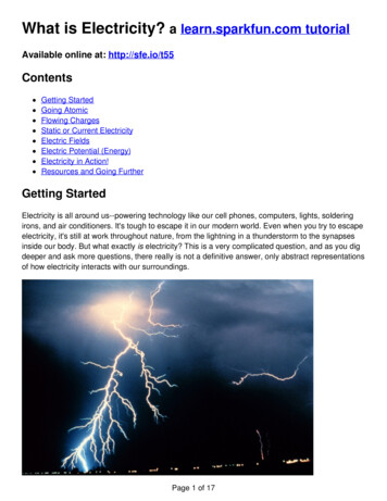
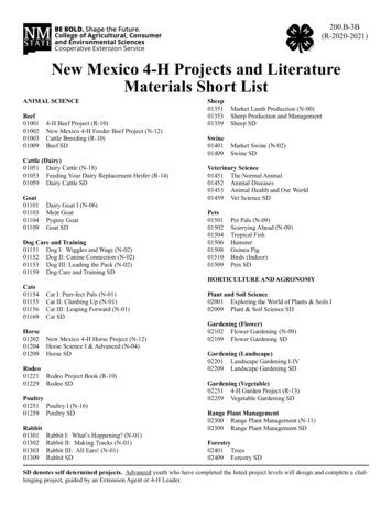
r dissipation:hVIV 2/RI2Rm*g*hvelocitydamping coefficient* velocity 2 Figure shows how energy is transferred from a batterywith certain potential energy (electrical potential) tothermal energy in resistor using a gravitational analog.
Ohm’s LawA resistor is an electrical circuit element which "resists" the flowof current in such a manner that electric charge moves through it atan approximately uniform velocity. This velocity varies with thevoltage across the resistor. The unit of resistance is the ohm ( ).Ohm’s Law defines the relationship between voltage V and currentI flowing through a resistor R:V IxRV Electric potential measured in units of volts (V)I Electric current is measured in units of Amperes (A)R Resistor is measure in units of ohms ( )
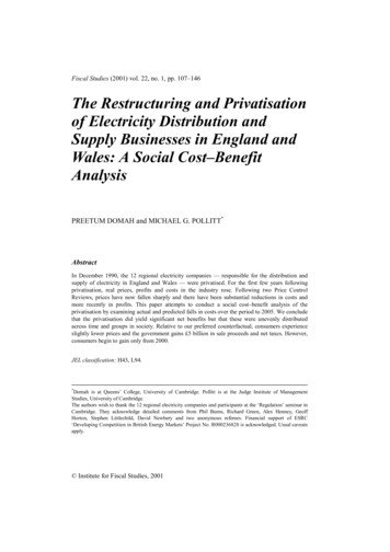
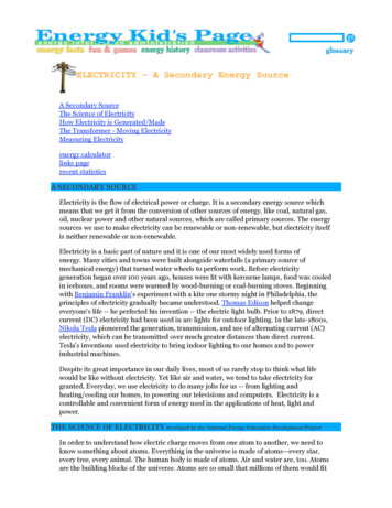
Ohm’s Law1/RCurrent (I)Slope of the curve isproportional to resistance of thedevice ( )Voltage (V)This clearly shows that a device follows Ohm’s law as long asthe resistance of the device is the same no matter what theapplied voltage we use to measure it. The plot of current as afunction of voltage appears as a straight line.
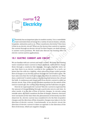
Light bulb is a ResistorV IxR (Ohm’s Law)P VxI (power provided by power supply)PR I2xR (power dissipated in resistor)AC (household (60HZ)DC
variableunitabbreviationsymbolrelation(t ) i(t)dchargecoulombCq(t)currentampereAi(t)dqi ( t ) ----dtenergyjouleJw(t)w ( t ) p ( t ) dtvoltagevoltVV(t)V(t) V ( t ) dt
Electrical and Mechanical SystemAnalogyElectromagnetic forceShockabsorber
How Power DistributionGrids Work
Power Plant power plant consists of aspinning electrical generator.Something has to spin thatgenerator -- it might be a waterwheel in a hydroelectric dam, alarge diesel engine or a gasturbine. But in most cases, thething spinning the generator is asteam turbine. The steammight be created by burningcoal, oil or natural gas. Or thesteam may come from a nuclearreactor like this one at theShearon Harris nuclear powerplant near Raleigh, NorthCarolina:
Alternating Current (AC) and DirectCurrent (DC)
Electromagnetic Wave Analogy between Electromagentic Waveand Mass-Spring mechanical system
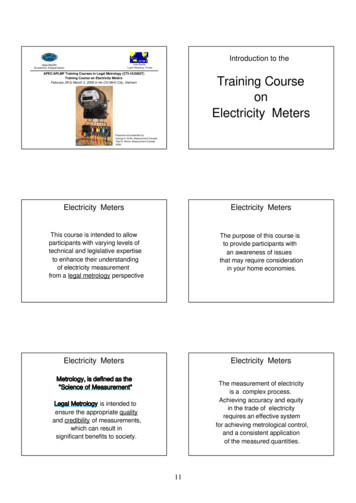
Single-phase power household electricalservice 120-volt AC(alternating current) Peak voltage 170volt 120 volt rms (rootmean square) 170 / 2
three phases areoffset 120 degreesfrom each other There are four wirescoming out of everypower plant: thethree phases plus aneutral or ground
Why three phases? at any given moment one of the three phasesis nearing a peak. High-power 3-phasemotors (used in industrial applications) andthings like 3-phase welding equipmenttherefore have even power output Four phases would not significantly improvethings but would add a fourth wire, so 3phase is the natural settling point
AC has at least three advantages over DC in a powerdistribution grid:1.Large electrical generators happen to generate AC naturally,so conversion to DC would involve an extra step.Transformers must have alternating current to operate, andwe will see that the power distribution grid depends ontransformers.It is easy to convert AC to DC but expensive to convert DC toAC, so if you were going to pick one or the other AC would bethe better choice.AC has less copper loss (I2R Joule heat) than DC and it'seasier and cheaper to produce too (high voltage transmission)2.3.4.
Advantages of DC over AC- reduction of noise and a reduction of danger. DCwill not interfere with wireless devices or createthat annoying hum in sound devices and is far lesslethal than AC current.- Energy can be stored- thinner conductors can be used since HVDC doesnot suffer from the skin effect
Advantages of HVDC over ACtransmissionThe advantage of HVDC is the ability to transmit large amounts ofpower over long distances with lower capital costs and with lowerlosses than AC. Depending on voltage level and construction details,losses are quoted as about 3% per 1,000 km.[14] High-voltage directcurrent transmission allows efficient use of energy sources remotefrom load centers.
In a number of applications HVDC is more effective than AC transmission.Examples include: Undersea cables, where high capacitance causes additional AC losses. (e.g.,250 km Baltic Cable between Sweden and Germany,[15] the 600 km NorNedcable between Norway and the Netherlands, and 290 km Basslink between theAustralian mainland and Tasmania[16]) Endpoint-to-endpoint long-haul bulk power transmission without intermediate'taps', for example, in remote areas Increasing the capacity of an existing power grid in situations where additionalwires are difficult or expensive to install Power transmission and stabilization between unsynchronised AC distributionsystems Connecting a remote generating plant to the distribution grid, for exampleNelson River Bipole Stabilizing a predominantly AC power-grid, without increasing prospectiveshort circuit current Reducing line cost. HVDC needs fewer conductors as there is no need tosupport multiple phases. Also, thinner conductors can be used since HVDCdoes not suffer from the skin effect Facilitate power transmission between different countries that use AC atdiffering voltages and/or frequencies Synchronize AC produced by renewable energy sources
The disadvantages of HVDC are in conversion, switching, control, availability and maintenance. HVDC is less reliable and has lower availability than AC systems, mainly due to the extraconversion equipment. Single pole systems have availability of about 98.5%, with about a third ofthe downtime unscheduled due to faults. Fault redundant bipole systems provide high availabilityfor 50% of the link capacity, but availability of the full capacity is about 97% to 98%.[17]The required static inverters are expensive and have limited overload capacity. At smallertransmission distances the losses in the static inverters may be bigger than in an AC transmissionline. The cost of the inverters may not be offset by reductions in line construction cost and lowerline loss. With two exceptions, all former mercury rectifiers worldwide have been dismantled orreplaced by thyristor units. Pole 1 of the HVDC scheme between the North and South Islands ofNew Zealand still uses mercury arc rectifiers, as does Pole 1 of the Vancouver Island link inCanada. Both are currently being replaced – in New Zealand by a new thyristor pole and in Canadaby a three-phase AC link.In contrast to AC systems, realizing multiterminal systems is complex, as is expanding existingschemes to multiterminal systems. Controlling power flow in a multiterminal DC system requiresgood communication between all the terminals; power flow must be actively regulated by theinverter control system instead of the inherent impedance and phase angle properties of thetransmission line.[18] Multi-terminal lines are rare. One is in operation at the Hydro Québec –New England transmission from Radisson to Sandy Pond.[19] Another example is the Sardiniamainland Italy link which was modified in 1989 to also provide power to the island of Corsica.[20]High voltage DC circuit breakers are difficult to build because some mechanism must be includedin the circuit breaker to force current to zero, otherwise arcing and contact wear would be too greatto allow reliable switching.Operating a HVDC scheme requires many spare parts to be kept, often exclusively for one systemas HVDC systems are less standardized than AC systems and technology changes faster.
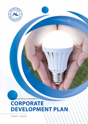
Transmission substation substation uses largetransformers to convert thegenerator's voltage (which isat the thousands of voltslevel) up to extremely highvoltages for long-distancetransmission on thetransmission grid. . Typical voltages for longdistance transmission are inthe range of 155,000 to765,000 volts in order toreduce line losses (lowvoltage requires a highercurrent and a higher voltagerequires a lower current.) transmission distance isabout 300 miles
Ohm’s Law V IR P VI (power produced by generator) P I2R (power dissipated in the power line)low voltage requires a higher current and a higher voltagerequires a lower current
High Power Transmission Line All power towers likethis have three wires forthe three phases. Manytowers, like the onesshown above, haveextra wires runningalong the tops of thetowers. These areground wires and arethere primarily in anattempt to attractlightning.
Power substation It has transformers that steptransmission voltages (in the tens orhundreds of thousands of voltsrange) down to distribution voltages(typically less than 10,000 volts).It has a "bus" that can split thedistribution power off in multipledirections.It often has circuit breakers andswitches so that the substation canbe disconnected from thetransmission grid or separatedistribution lines can bedisconnected from the substationwhen necessary.
Distribution Bus The bus distributes power totwo separate sets of distributionlines at two different voltages.The smaller transformersattached to the bus are steppingthe power down to standard linevoltage (usually 7,200 volts) forone set of lines, while powerleaves in the other direction atthe higher voltage of the maintransformer. The power leavesthis substation in two sets ofthree wires, each headed downthe road in a different direction
Distribution Bus In the typical scenepictured on the right,the three wires at thetop of the poles are thethree wires for the 3phase power. Thefourth wire lower on thepoles is the ground wire.In some cases there willbe additional wires,typically phone or cableTV lines riding on thesame poles.
Regulator Bank You will also findregulator banks locatedalong the line, eitherunderground or in theair. They regulate thevoltage on the line toprevent undervoltageand overvoltageconditions.
Regulator bank Up toward the top are threeswitches that allow thisregulator bank to bedisconnected formaintenance whennecessary:
Neighborhood Bus line At this point, we have typicalline voltage at something like7,200 volts running throughthe neighborhood on threewires (with a fourth groundwire lower on the pole):
Tap A house needs only oneof the three phases, sotypically you will seethree wires runningdown a main road, andtaps for one or two ofthe phases running offon side streets. Picturedbelow is a 3-phase to 2phase tap, with the twophases running off tothe right
2 phase to 1 phase tap Here is a 2-phase to1-phase tap, withthe single phaserunning out to theright:
And finally we are down to thewire that brings power to yourhouse! Past a typical houseruns a set of poles with onephase of power (at 7,200 volts)and a ground wire (althoughsometimes there will be two orthree phases on the pole,depending on where the houseis located in the distribution grid).At each house, there is atransformer drum attached tothe pole, like this:underground and there aregreen transformer boxes atevery house or two
Transformer The transformer's job isto reduce the 7,200volts down to the 240volts that makes upnormal householdelectrical service. Let'slook at this pole onemore time, from thebottom, to see what isgoing on:
There is a bare wire running down the pole.This is a grounding wire. Every utility pole on theplanet has one. If you ever watch the powercompany install a new pole, you will see that theend of that bare wire is stapled in a coil to thebase of the pole and therefore is in directcontact with the earth, running 6 to 10 feet (1.8to 3 m) underground. It is a good, solid groundconnection. If you examine a pole carefully, youwill see that the ground wire running betweenpoles (and often the guy wires) are attached tothis direct connection to ground.There are two wires running out of thetransformer and three wires running to thehouse.The two from the transformer are insulated, andthe third one is bare. The bare wire is the groundwire. The two insulated wires each carry 120volts, but they are 180 degrees out of phase sothe difference between them is 240 volts. Thisarrangement allows a homeowner to use both120-volt and 240-volt appliances. Thetransformer is wired in this sort of configuration:
Meter The 240 volts entersyour house througha typical watt-hourmeter like this one:
Fuses and Circuit Breakers Fuses and circuit breakers are safety devices. Let's say that you did nothave fuses or circuit breakers in your house and something "wentwrong." What could possibly go wrong? Here are some examples:A fan motor burns out a bearing, seizes, overheats and melts, causing adirect connection between power and ground.A wire comes loose in a lamp and directly connects power to ground.A mouse chews through the insulation in a wire and directly connectspower to ground.Someone accidentally vacuums up a lamp wire with the vacuum cleaner,cutting it in the process and directly connecting power to ground.A person is hanging a picture in the living room and the nail used for saidpicture happens to puncture a power line in the wall, directly connectingpower to ground.circuit breaker panel
Fuses and Circuit Breakers Fuse uses a thin piece offoil or wire quicklyvaporizes when anoverload of current runsthrough it circuit breaker usesthe heat from anoverload to trip a switch,and circuit breakers aretherefore resettable.
Fuses and Circuit Breakers The main breaker letsyou cut power to theentire panel whennecessary. Within thisoverall setup, all of thewires for the differentoutlets and lights in thehouse each have aseparate circuit breakeror fuse:
Outlet If the circuit breakeris on, then powerflows through thewire in the wall andmakes its wayeventually to its finaldestination, theoutlet or Lightswitch
Electrical Power Energy dissipated in an electrical or electronic circuit ordevice per unit of time. The electrical energy supplied by acurrent to an appliance enables it to do work or providesome other form of energy such as light or heat. Electricpower is usually measured in Watts, kilowatts (1,000watts), and megawatts (1,000,000 watts). The amount ofelectrical energy used by an appliance is found bymultiplying its consumed power by the length of time ofoperation. The units of electrical energy are usually wattseconds (joules), watt-hours, or kilowatt-hours. Forcommercial purposes the kilowatt-hour is the unit ofchoice.
Conserving ElectricityUnit of Electrical Power?x2Energy Work F dxx1Nm J (Joul)PE negative work; KE positive work; other forms of energy RF, heat, light etc.Power Energy/timeWatts J/ sec
Rating Your ApplianceThe electric company actually bills you for the amount of energy thatyou use. But your appliances are rated by the amount of power thatthey use. You can easily find the amount of energy used by solving thepower equation for energy. You get:Energy Power x timeunits of kilowatt hours
Calculating your electric bill Now all you need to know is how muchyour electric utility or company charges youfor energy. This will usually be in the unitsof per kw hr. Then you just multiply thekw hrs by the per kw hr, and you end upwith the cost for that appliance for theamount of time that you have used it.
Sample Calculations Let's say that you found that your microwave oven has apower rating of 120 watts. To convert that into kilowattsyou must divide by 1000 as follows. Place this number inthe table.
Sample Calculations You estimate that your microwave oven is used 3 hours perday. Multiply by 365 days per year to get the hours usedper year as follows:
Sample Calculations Now you can calculate your energy consumption bymultiplying the power in kw times the time used in hr/yr asfollows:
Single switch wiring
Two switches wiring
Electrical Wiring
Assignment Can you connect a switch to a light fixture?(10%) If you have more than one entrance to aroom, it's handy to have more than oneswitch to turn the lights on and off. Can you figure out any other ways ofconnecting two switches? (20%) Can you explain the way the current flowacross the switches?(20%)
Can you do the three switchesconfiguration? (20%) How many different ways of wiring canyou come up? (20%) How to connect multiple light fixture to singleor multiple switches? (10%) Any other configuration you can think ofconnecting the wire in your house safely? (extracredit (50%)
Electric current represents the flow of electric charge (usually electrons) through a wire or other conductor of electricity. Electric current is measured in units of Amperes (A) while charge is in units of Coulombs (C). The symbol I is used for current and Q for charge. Thus, a 1 A current represents the flow of 1 C/sec of charge.