Transcription
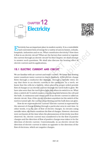
CHAPTER12ElectricityElectricity has an important place in modern society. It is a controllableand convenient form of energy for a variety of uses in homes, schools,hospitals, industries and so on. What constitutes electricity? How doesit flow in an electric circuit? What are the factors that control or regulatethe current through an electric circuit? In this Chapter, we shall attemptto answer such questions. We shall also discuss the heating effect ofelectric current and its applications.12.1 ELECTRIC CURRENT AND CIRCUITWe are familiar with air current and water current. We know that flowingwater constitute water current in rivers. Similarly, if the electric chargeflows through a conductor (for example, through a metallic wire), wesay that there is an electric current in the conductor. In a torch, weknow that the cells (or a battery, when placed in proper order) provideflow of charges or an electric current through the torch bulb to glow. Wehave also seen that the torch gives light only when its switch is on. Whatdoes a switch do? A switch makes a conducting link between the cell andthe bulb. A continuous and closed path of an electric current is called anelectric circuit. Now, if the circuit is broken anywhere (or the switch of thetorch is turned off ), the current stops flowing and the bulb does not glow.How do we express electric current? Electric current is expressed bythe amount of charge flowing through a particular area in unit time. Inother words, it is the rate of flow of electric charges. In circuits usingmetallic wires, electrons constitute the flow of charges. However, electronswere not known at the time when the phenomenon of electricity was firstobserved. So, electric current was considered to be the flow of positivecharges and the direction of flow of positive charges was taken to be thedirection of electric current. Conventionally, in an electric circuit thedirection of electric current is taken as opposite to the direction of theflow of electrons, which are negative charges.2021–22
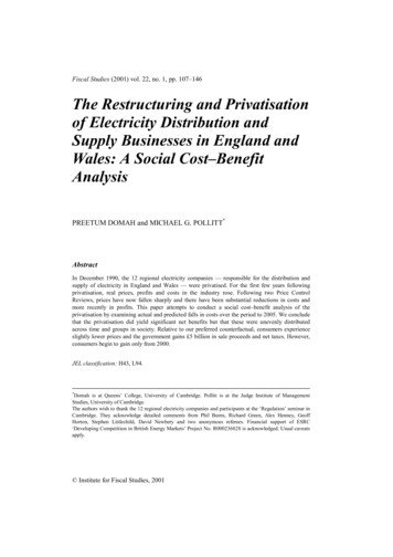
If a net charge Q, flows across any cross-section of a conductor intime t, then the current I, through the cross-section isI Qt(12.1)The SI unit of electric charge is coulomb (C), which is equivalent tothe charge contained in nearly 6 1018 electrons. (We know that anelectron possesses a negative charge of 1.6 10–19 C.) The electriccurrent is expressed by a unit called ampere (A), named after theFrench scientist, Andre-Marie Ampere (1775–1836). One ampere isconstituted by the flow of one coulomb of charge per second, that is,1 A 1 C/1 s. Small quantities of current are expressed in milliampere(1 mA 10–3 A) or in microampere (1 µA 10–6 A).An instrument called ammeter measures electriccurrent in a circuit. It is always connected in seriesin a circuit through which the current is to bemeasured. Figure 12.1 shows the schematicdiagram of a typical electric circuit comprising acell, an electric bulb, an ammeter and a plug key.Note that the electric current flows in the circuitfrom the positive terminal of the cell to the negativeterminal of the cell through the bulb and ammeter.Figure 12.1A schematic diagram of an electric circuitcomprising – cell, electric bulb, ammeter andplug keyExample 12.1A current of 0.5 A is drawn by a filament of an electric bulb for 10minutes. Find the amount of electric charge that flows through thecircuit.SolutionWe are given, I 0.5 A; t 10 min 600 s.From Eq. (12.1), we haveQ It 0.5 A 600 s 300 CQUESTION1.What does an electric circuit mean?2.Define the unit of current.3.Calculate the number of electrons constituting one coulomb of charge.S?Science2002021–22
More to Know!‘Flow’ of charges inside a wireHow does a metal conduct electricity? You would think that a low-energy electronwould have great difficulty passing through a solid conductor. Inside the solid, theatoms are packed together with very little spacing between them. But it turns outthat the electrons are able to ‘travel’ through a perfect solid crystal smoothly andeasily, almost as if they were in a vacuum. The ‘motion’ of electrons in a conductor,however, is very different from that of charges in empty space. When a steady currentflows through a conductor, the electrons in it move with a certain average ‘drift speed’.One can calculate this drift speed of electrons for a typical copper wire carrying asmall current, and it is found to be actually very small, of the order of 1 mm s-1. Howis it then that an electric bulb lights up as soon as we turn the switch on? It cannot bethat a current starts only when an electron from one terminal of the electric supplyphysically reaches the other terminal through the bulb, because the physical drift ofelectrons in the conducting wires is a very slow process. The exact mechanism of thecurrent flow, which takes place with a speed close to the speed of light, is fascinating,but it is beyond the scope of this book. Do you feel like probing this question at anadvanced level?12.2 ELECTRIC POTENTIAL AND POTENTIAL DIFFERENCEWhat makes the electric charge to flow? Let us consider the analogy offlow of water. Charges do not flow in a copper wire by themselves, just aswater in a perfectly horizontal tube does not flow. If one end of the tubeis connected to a tank of water kept at a higher level, such that there is apressure difference between the two ends of the tube, water flows out ofthe other end of the tube. For flow of charges in a conducting metallicwire, the gravity, of course, has no role to play; the electrons move onlyif there is a difference of electric pressure – called the potential difference –along the conductor. This difference of potential may be produced by abattery, consisting of one or more electric cells. The chemical action withina cell generates the potential difference across the terminals of the cell,even when no current is drawn from it. When the cell is connected to aconducting circuit element, the potential difference sets the charges inmotion in the conductor and produces an electric current. In order tomaintain the current in a given electric circuit, the cell has to expend itschemical energy stored in it.We define the electric potential difference between two points in anelectric circuit carrying some current as the work done to move a unitcharge from one point to the other –Potential difference (V) between two points Work done (W )/Charge (Q)V W/Q(12.2)The SI unit of electric potential difference is volt (V), named afterAlessandro Volta (1745 –1827), an Italian physicist. One volt is the201Electricity2021–22
potential difference between two points in a current carrying conductorwhen 1 joule of work is done to move a charge of 1 coulomb from onepoint to the other.Therefore, 1 volt 1 joule1 coulomb(12.3)1 V 1 J C–1The potential difference is measured by means of an instrument calledthe voltmeter. The voltmeter is always connected in parallel across thepoints between which the potential difference is to be measured.Example 12.2How much work is done in moving a charge of 2 C across two pointshaving a potential difference 12 V?SolutionThe amount of charge Q, that flows between two points at potentialdifference V ( 12 V) is 2 C. Thus, the amount of work W, done inmoving the charge [from Eq. (12.2)] isW QVQ 12 V 2 C 24 J.UESTIONS1.Name a device that helps to maintain a potential difference across aconductor.2.What is meant by saying that the potential difference between two pointsis 1 V?3.How much energy is given to each coulomb of charge passing through a6 V battery?12.3 CIRCUIT DIAGRAMWe know that an electric circuit, as shown in Fig. 12.1, comprises a cell(or a battery), a plug key, electrical component(s), and connecting wires.It is often convenient to draw a schematic diagram, in which differentcomponents of the circuit are represented by the symbols convenientlyused. Conventional symbols used to represent some of the mostcommonly used electrical components are given in Table 12.1.Science2022021–22
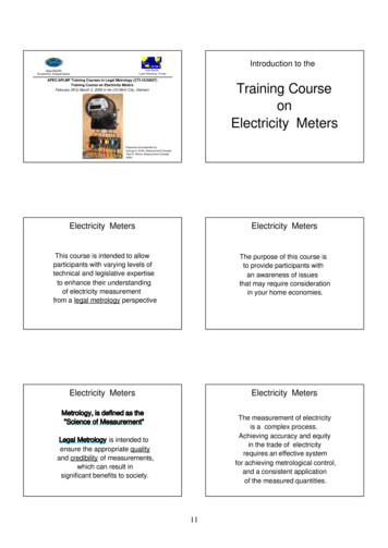
Table 12.1 Symbols of some commonly used components in circuit diagramsSl.No.Components1An electric cell2A battery or a combination of cells3Plug key or switch (open)4Plug key or switch (closed)5A wire joint6Wires crossing without joining7Electric bulb8A resistor of resistance R9Variable resistance or rheostat10Ammeter11VoltmeterSymbolsoror12.4 OHM’S LALAWWIs there a relationship between the potential difference across aconductor and the current through it? Let us explore with an Activity.Activity 12.1nSet up a circuit as shown in Fig. 12.2, consisting of a nichrome wire XY of length, say 0.5 m,an ammeter, a voltmeter and four cells of 1.5 V each. (Nichrome is an alloy of nickel, chromium,manganese, and iron metals.)203Electricity2021–22
nnnnnFirst use only one cell as the source in thecircuit. Note the reading in the ammeter I,for the current and reading of the voltmeterV for the potential difference across thenichrome wire XY in the circuit. Tabulatethem in the Table given.Next connect two cells in the circuit and notethe respective readings of the ammeter andvoltmeter for the values of current throughthe nichrome wire and potential differenceacross the nichrome wire.Repeat the above steps using three cells andthen four cells in the circuit separately.Calculate the ratio of V to I for each pair ofpotential difference V and current I.S.No.Number of cellsused in thecircuit11223344Current throughthe nichromewire, I(ampere)Figure 12.2 Electric circuit for studying Ohm’s lawPotential differenceacross thenichromewire, V (volt)V/I(volt/ampere)Plot a graph between V and I, and observe the nature of the graph.Figure 12.3V–I graph for a nichrome wire. Astraight line plot shows that as thecurrent through a wire increases, thepotential difference across the wireincreases linearly – this is Ohm’s law.In this Activity, you will find that approximately thesame value for V/I is obtained in each case. Thus the V–Igraph is a straight line that passes through the origin ofthe graph, as shown in Fig. 12.3. Thus, V/I is a constantratio.In 1827, a German physicist Georg Simon Ohm(1787–1854) found out the relationship between the currentI, flowing in a metallic wire and the potential difference acrossits terminals. The potential difference, V, across the ends ofa given metallic wire in an electric circuit is directlyproportional to the current flowing through it, provided itstemperature remains the same. This is called Ohm’s law. Inother words –V I(12.4)orV/I constant RorV IR(12.5)In Eq. (12.4), R is a constant for the given metallic wireat a given temperature and is called its resistance. It isthe property of a conductor to resist the flow of chargesScience2042021–22
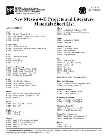
through it. Its SI unit is ohm, represented by the Greek letter Ω. Accordingto Ohm’s law,R V/I(12.6)If the potential difference across the two ends of a conductor is 1 Vand the current through it is 1 A, then the resistance R, of the conductor1 voltis 1 Ω. That is, 1 ohm 1 ampereAlso from Eq. (12.5) we getI V/R(12.7)It is obvious from Eq. (12.7) that the current through a resistor isinversely proportional to its resistance. If the resistance is doubled thecurrent gets halved. In many practical cases it is necessary to increaseor decrease the current in an electric circuit. A component used toregulate current without changing the voltage source is called variableresistance. In an electric circuit, a device called rheostat is often usedto change the resistance in the circuit. We will now study about electricalresistance of a conductor with the help of following Activity.Activity 12.2nnTake a nichrome wire, a torch bulb, a 10 W bulb and an ammeter (0 – 5 A range), a plugkey and some connecting wires.Set up the circuit by connecting four dry cells of 1.5 V each in series with the ammeterleaving a gap XY in the circuit, as shown in Fig. 12.4.Figure 12.4nnnnnComplete the circuit by connecting the nichrome wire in the gap XY. Plug the key. Notedown the ammeter reading. Take out the key from the plug. [Note: Always take out the keyfrom the plug after measuring the current through the circuit.]Replace the nichrome wire with the torch bulb in the circuit and find the current through it bymeasuring the reading of the ammeter.Now repeat the above step with the 10 W bulb in the gap XY.Are the ammeter readings different for different components connected in the gap XY?What do the above observations indicate?You may repeat this Activity by keeping any material component in the gap. Observe theammeter readings in each case. Analyse the observations.In this Activity we observe that the current is different for differentcomponents. Why do they differ? Certain components offer an easy pathfor the flow of electric current while the others resist the flow. We know205Electricity2021–22
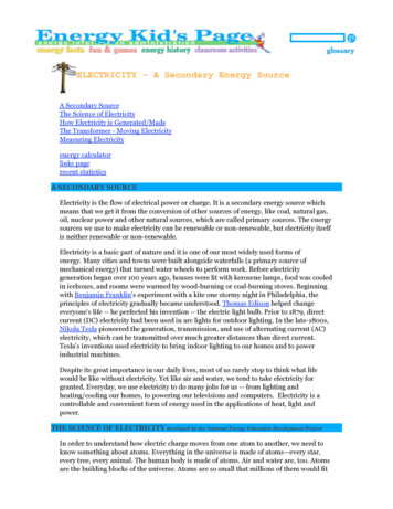
that motion of electrons in an electric circuit constitutes an electriccurrent. The electrons, however, are not completely free to move within aconductor. They are restrained by the attraction of the atoms amongwhich they move. Thus, motion of electrons through a conductor isretarded by its resistance. A component of a given size that offers a lowresistance is a good conductor. A conductor having some appreciableresistance is called a resistor. A component of identical size that offers ahigher resistance is a poor conductor. An insulator of the same size offerseven higher resistance.CTORS ON WHICH THE RESISTANCE OF AFACTORSRESISTANCE12.5 FACONDUCTOR DEPENDSActivity 12.3nComplete an electric circuit consisting of a cell, an ammeter, a nichrome wire of length l[say, marked (1)] and a plug key, as shown in Fig. 12.5.Figure 12.5 Electric circuit to study the factors on which the resistance of conducting wires dependsnnnnnnnnNow, plug the key. Note the current in the ammeter.Replace the nichrome wire by another nichrome wire of same thickness but twice thelength, that is 2l [marked (2) in the Fig. 12.5].Note the ammeter reading.Now replace the wire by a thicker nichrome wire, of the same length l [marked (3)]. Athicker wire has a larger cross-sectional area. Again note down the current through thecircuit.Instead of taking a nichrome wire, connect a copper wire [marked (4) in Fig. 12.5] in the circuit.Let the wire be of the same length and same area of cross-section as that of the first nichromewire [marked (1)]. Note the value of the current.Notice the difference in the current in all cases.Does the current depend on the length of the conductor?Does the current depend on the area of cross-section of the wire used?It is observed that the ammeter reading decreases to one-half whenthe length of the wire is doubled. The ammeter reading is increased whena thicker wire of the same material and of the same length is used in thecircuit. A change in ammeter reading is observed when a wire of differentmaterial of the same length and the same area of cross-section is used.On applying Ohm’s law [Eqs. (12.5) – (12.7)], we observe that theScience2062021–22
resistance of the conductor depends (i) on its length, (ii) on its area ofcross-section, and (iii) on the nature of its material. Precise measurementshave shown that resistance of a uniform metallic conductor is directlyproportional to its length (l ) and inversely proportional to the area ofcross-section (A). That is,R l(12.8)andR 1/A(12.9)Combining Eqs. (12.8) and (12.9) we getR or,lAR ρlA(12.10)where ρ (rho) is a constant of proportionality and is called the electricalresistivity of the material of the conductor. The SI unit of resistivity isΩ m. It is a characteristic property of the material. The metals and alloyshave very low resistivity in the range of 10–8 Ω m to 10–6 Ω m. They aregood conductors of electricity. Insulators like rubber and glass haveresistivity of the order of 1012 to 1017 Ω m. Both the resistance andresistivity of a material vary with temperature.Table 12.2 reveals that the resistivity of an alloy is generally higherthan that of its constituent metals. Alloys do not oxidise (burn) readilyat high temperatures. For this reason, they are commonly used inelectrical heating devices, like electric iron, toasters etc. Tungsten is usedalmost exclusively for filaments of electric bulbs, whereas copper andaluminium are generally used for electrical transmission lines.Table 12.2 Electrical resistivity* of some substances at 20 CResistivity (ΩΩ m)Material1.60 10–81.62 10–82.63 10–85.20 10–86.84 10–810.0 10–812.9 10–894.0 10–81.84 y of Cu and Ni)Manganin(alloy of Cu, Mn and Ni)Nichrome(alloy of Ni, Cr, Mn and Fe)Insulators49 10–644 10–6100 10–61010 – 10141013 – 10161015 – 10171012 - 10131012GlassHard rubberEboniteDiamondPaper (dry)* You need not memorise these values. You can use these values for solving numericalproblems.207Electricity2021–22
Example 12.3(a) How much current will an electric bulb draw from a 220 V source,if the resistance of the bulb filament is 1200 Ω? (b) How muchcurrent will an electric heater coil draw from a 220 V source, ifthe resistance of the heater coil is 100 Ω?Solution(a) We are given V 220 V; R 1200 Ω.From Eq. (12.6), we have the current I 220 V/1200 Ω 0.18 A.(b) We are given, V 220 V, R 100 Ω.From Eq. (12.6), we have the current I 220 V/100 Ω 2.2 A.Note the difference of current drawn by an electric bulb and electricheater from the same 220 V source!Example 12.4The potential difference between the terminals of an electric heateris 60 V when it draws a current of 4 A from the source. Whatcurrent will the heater draw if the potential difference is increasedto 120 V?SolutionWe are given, potential difference V 60 V, current I 4 A.V60 V 15 Ω .I4AWhen the potential difference is increased to 120 V the current isgiven byAccording to Ohm’s law, R current V120 V 8 A.R15 ΩThe current through the heater becomes 8 A.Example 12.5Resistance of a metal wire of length 1 m is 26 Ω at 20 C. If thediameter of the wire is 0.3 mm, what will be the resistivity of themetal at that temperature? Using Table 12.2, predict the materialof the wire.SolutionWe are given the resistance R of the wire 26 Ω, the diameterd 0.3 mm 3 10-4 m, and the length l of the wire 1 m.Therefore, from Eq. (12.10), the resistivity of the given metallic wire isρ (RA/l ) (R πd2/4l )Substitution of values in this givesρ 1.84 10–6 Ω mThe resistivity of the metal at 20 C is 1.84 10–6 Ω m. FromTable 12.2, we see that this is the resistivity of manganese.Science2082021–22
Example 12.6A wire of given material having length l and area of cross-section Ahas a resistance of 4 Ω. What would be the resistance of another wireof the same material having length l/2 and area of cross-section 2A?SolutionFor first wirelAR1 ρ 4ΩNow for second wireR2 ρl /22AR2 14 14ρlAR1R 2 1ΩThe resistance of the new wire is 1Ω.QUESTIONS1.On what factors does the resistance of a conductor depend?2.Will current flow more easily through a thick wire or a thin wire of thesame material, when connected to the same source? Why?3.Let the resistance of an electrical component remains constant whilethe potential difference across the two ends of the component decreasesto half of its former value. What change will occur in the current throughit?4.Why are coils of electric toasters and electric irons made of an alloyrather than a pure metal?5.Use the data in Table 12.2 to answer the following –(a) Which among iron and mercury is a better conductor?(b) Which material is the best conductor?12.6 RESISTANCE OF A SYSTEM OF RESISTORSRESISTANCEIn preceding sections, we learnt about some simple electric circuits. Wehave noticed how the current through a conductor depends upon itsresistance and the potential difference across its ends. In various electricalgadgets, we often use resistors in various combinations. We now thereforeintend to see how Ohm’s law can be applied to combinations of resistors.There are two methods of joining the resistors together. Figure 12.6shows an electric circuit in which three resistors having resistances R1,R2 and R3, respectively, are joined end to end. Here the resistors are saidto be connected in series.209Electricity2021–22
Figure 12.6 Resistors in seriesFigure 12.7 shows a combination of resistors in which three resistorsare connected together between points X and Y. Here, the resistors aresaid to be connected in parallel.Figure 12.7 Resistors in parallel12.6.1 Resistors in SeriesWhat happens to the value of current when a number of resistors areconnected in series in a circuit? What would be their equivalentresistance? Let us try to understand these with the help of the followingactivities.Activity 12.4nnnnJoin three resistors of different values in series. Connect themwith a battery, an ammeter and a plug key, as shown in Fig. 12.6.You may use the resistors of values like 1 Ω, 2 Ω, 3 Ω etc., and abattery of 6 V for performing this Activity.Plug the key. Note the ammeter reading.Change the position of ammeter to anywhere in between theresistors. Note the ammeter reading each time.Do you find any change in the value of current through theammeter?Science2102021–22
You will observe that the value of the current in the ammeter is thesame, independent of its position in the electric circuit. It means that ina series combination of resistors the current is the same in every part ofthe circuit or the same current through each resistor.Activity 12.5nnnIn Activity 12.4, insert a voltmeter across the ends X and Y of theseries combination of three resistors, as shown in Fig. 12.6.Plug the key in the circuit and note the voltmeter reading. Itgives the potential difference across the series combination ofresistors. Let it be V. Now measure the potential difference acrossthe two terminals of the battery. Compare the two values.Take out the plug key and disconnect the voltmeter. Now insertthe voltmeter across the ends X and P of the first resistor, asshown in Fig. 12.8.Figure 12.8nnnPlug the key and measure the potential difference across the firstresistor. Let it be V1.Similarly, measure the potential difference across the other tworesistors, separately. Let these values be V2 and V3, respectively.Deduce a relationship between V, V1, V2 and V3.You will observe that the potential difference V is equal to the sum ofpotential differences V1, V2, and V3. That is the total potential differenceacross a combination of resistors in series is equal to the sum of potentialdifference across the individual resistors. That is,V V1 V2 V3(12.11)In the electric circuit shown in Fig. 12.8, let I be the current throughthe circuit. The current through each resistor is also I. It is possible toreplace the three resistors joined in series by an equivalent single resistorof resistance R, such that the potential difference V across it, and thecurrent I through the circuit remains the same. Applying the Ohm’s lawto the entire circuit, we haveV IR(12.12)211Electricity2021–22
On applying Ohm’s law to the three resistors separately, we furtherhaveV1 I R1[12.13(a)]andV2 I R2[12.13(b)]V3 I R3[12.13(c)]From Eq. (12.11),I R I R1 I R2 I R3orRs R1 R2 R3(12.14)We can conclude that when several resistors are joined in series, theresistance of the combination Rs equals the sum of their individualresistances, R1, R2, R3, and is thus greater than any individual resistance.Example 12.7An electric lamp, whose resistance is 20 Ω, and a conductor of 4 Ωresistance are connected to a 6 V battery (Fig. 12.9). Calculate (a) thetotal resistance of the circuit, (b) the current through the circuit, and(c) the potential difference across the electric lamp and conductor.Figure 12.9 An electric lamp connected in series witha resistor of 4 Ω to a 6 V batterySolutionThe resistance of electric lamp, R 1 20 Ω,The resistance of the conductor connected in series, R 2 4 Ω.Then the total resistance in the circuitR R1 R2Rs 20 Ω 4 Ω 24 Ω.The total potential difference across the two terminals of the batteryV 6 V.Now by Ohm’s law, the current through the circuit is given byI V/Rs 6 V/24 Ω 0.25 A.Science2122021–22
Applying Ohm’s law to the electric lamp and conductor separately,we get potential difference across the electric lamp,V1 20 Ω 0.25 A 5 V;and,that across the conductor, V2 4 Ω 0.25 A 1 V.Suppose that we like to replace the series combination of electriclamp and conductor by a single and equivalent resistor. Its resistancemust be such that a potential difference of 6 V across the batteryterminals will cause a current of 0.25 A in the circuit. The resistanceR of this equivalent resistor would beR V/I 6 V/ 0.25 A 24 Ω.This is the total resistance of the series circuit; it is equal to the sumof the two resistances.QUESTIONS1.Draw a schematic diagram of a circuit consisting of a battery of threecells of 2 V each, a 5 Ω resistor, an 8 Ω resistor, and a 12 Ω resistor, anda plug key, all connected in series.2.Redraw the circuit of Question 1, putting in an ammeter to measurethe current through the resistors and a voltmeter to measure thepotential difference across the 12 Ω resistor. What would be the readingsin the ammeter and the voltmeter?12.6.2 Resistors in ParallelNow, let us consider the arrangement of three resistors joined in parallelwith a combination of cells (or a battery), as shown in Fig.12.7.Activity 12.6nnMake a parallel combination, XY, of threeresistors having resistances R1, R2, and R3,respectively. Connect it with a battery, aplug key and an ammeter, as shown inFig. 12.10. Also connect a voltmeter inparallel with the combination of resistors.Plug the key and note the ammeter reading.Let the current be I. Also take the voltmeterreading. It gives the potential difference V,across the combination. The potentialdifference across each resistor is also V. Thiscan be checked by connecting the voltmeteracross each individual resistor (seeFig. 12.11).Figure 12.10213Electricity2021–22
nTake out the plug from the key. Remove the ammeter and voltmeter from the circuit.Insert the ammeter in series with the resistor R1, as shown in Fig. 12.11. Note the ammeterreading, I1.Figure 12.11nSimilarly, measure the currents through R 2 and R 3. Let these be I 2 and I 3, respectively.What is the relationship between I, I1, I2 and I3 ?It is observed that the total current I, is equal to the sum of theseparate currents through each branch of the combination.I I1 I2 I3(12.15)Let Rp be the equivalent resistance of the parallel combination ofresistors. By applying Ohm’s law to the parallel combination of resistors,we haveI V/Rp(12.16)On applying Ohm’s law to each resistor, we haveI1 V /R1; I2 V /R2; and I3 V /R3(12.17)From Eqs. (12.15) to (12.17), we haveV/Rp V/R1 V/R2 V/R3or1/Rp 1/R1 1/R2 1/R3(12.18)Thus, we may conclude that the reciprocal of the equivalent resistanceof a group of resistances joined in parallel is equal to the sum of thereciprocals of the individual resistances.Example 12.8In the circuit diagram given in Fig. 12.10, suppose the resistors R1,R2 and R 3 have the values 5 Ω, 10 Ω, 30 Ω, respectively, which havebeen connected to a battery of 12 V. Calculate (a) the current througheach resistor, (b) the total current in the circuit, and (c) the total circuitresistance.SolutionR1 5 Ω, R2 10 Ω, and R3 30 Ω.Potential difference across the battery, V 12 V.This is also the potential difference across each of the individualresistor; therefore, to calculate the current in the resistors, we useOhm’s law.The current I1, through R1 V/ R12.4 A.I1 12 V/5 Ω Science2142021–22
The current I2, through R2 V/ R2I2 12 V/10 Ω 1.2 A.The current I3, through R3 V/R3I3 12 V/30 Ω 0.4 A.The total current in the circuit,I I1 I2 I3 (2.4 1.2 0.4) A 4AThe total resistance Rp, is given by [Eq. (12.18)]1 1 11 1 R p 5 10 30 3Thus, Rp 3 Ω.Example 12.9If in Fig. 12.12, R 1 10 Ω, R2 40 Ω, R3 30 Ω, R4 20 Ω, R5 60 Ω,and a 12 V battery is connected to the arrangement. Calculate(a) the total resistance in the circuit, and (b) the total current flowingin the circuit.SolutionSuppose we replace the parallel resistors R1 and R 2 by anequivalent resistor of resistance, R ′. Similarly we replacethe parallel resistors R3, R4 and R5 by an equivalent singleresistor of resistance R ″. Then using Eq. (12.18), we have1/ R′ 1/10 1/40 5/40; that is R′ 8 Ω.Similarly,1/ R″ 1/30 1/20 1/60 6/60;that is, R″ 10 Ω.Thus, the total resistance, R R′ R″ 18 Ω.To calculate the current, we use Ohm’s law, and getI V/R 12 V/18 Ω 0.67 A.We have seen that in a series circuit the current is constant throughoutthe electric circuit. Thus it is obviously impracticable to connect an electricbulb and an electric heater in series, because they need currents of widelydifferent values to operate properly (see Example 12.3). Another majordisadvantage of a series circuit is that when one component fails the circuit isbroken and none of the components works. If you have used ‘fairy lights’ todecorate buildings on festivals, on marriage celebrations etc., you might haveseen the electrician spending lot of time in trouble-locating and replacing the‘dead’ bulb – each has to be tested to find which has fused or gone. On theother hand, a parallel circuit divides the current through the electrical gadgets.The total resistance in a parallel circuit is decreased as per Eq. (12.18). Thisis helpful particularly when each gadget has different resistance and requiresdifferent current to operate properly.Figure 12.12An electric circuit showingthe combination of seriesand parallel resistors215Electricity2021–22
QUESTIONS1.Judge the equivalent resistance when the following are connected inparallel – (a) 1 Ω and 106 Ω, (b) 1 Ω and 103 Ω, and 106 Ω.2.An electric lamp of 100 Ω, a toaster of resis
Electricity CHAPTER12 Electricity has an important place in modern society. It is a controllable and convenient form of energy for a variety of uses in homes, schools, hospitals, industries and so on. What constitutes electricity? How does it flow in an electric circui