Transcription
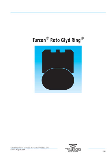
Turcon Roto Glyd Ring Latest information available at www.tss.trelleborg.comEdition August 2009241
Latest information available at www.tss.trelleborg.comEdition August 2009242
Turcon Roto Glyd Ring n TURCON ROTARY SEALS - ELASTOMER ENERGIZEDn Turcon Roto Glyd Ring Description The Turcon Roto Glyd Ring is used to seal rods, shafts,axles, bores, rotary transmission leadthroughs, journals,swivels etc. with rotary or oscillating movement.The seal is double-acting and can be exposed to pressurefrom one, or from both sides.A standard diameter range for each profile size is assignedto the series numbers in Table LXXVI and LXXVIII. Thisrecommendation applies to all new constructions.Different dimensions are available on request.Advantages- Available for internal and external sealing applications- Low frictionNotches- Stick-slip-free starting, no sticking- High abrasion resistance and dimensional stability- Simple groove design, small groove dimensions- Lubricant reservoirGrooves- Available in all sizes up to 2700 mm diameter(to 2600 mm for rod seals)Technical dataO-RingTurcon Roto Glyd Ring ppFigure 111Operatingpressure:Up to 30 MPaSpeed:Up to 2 m/sTemperature:- 45 C to 200 C *)(depending on O—Ring material)Media:Mineral oil-based hydraulic fluids,flame retardant hydraulic fluids,environmentally safe hydraulic fluids(bio-oils), water, air and others,depending on O—Ring material.Note:For continuous operation attemperatures over 60 C, pressureand speed must be limited.Turcon Roto Glyd Ring It consists of a seal ring of Turcon material and is activatedby an O—Ring as an elastic energizing element.The contact surface profile of the seal ring is speciallydesigned for use under high pressures and at low slidingspeeds.Depending on the profile cross-section of the seal, thecontact surface has one or two continuous machinedgrooves. These have the following functions:Important Note:The above data are maximum values and cannotbe used at the same time, e. g. the maximumoperating speed depends on material type,pressure and temperature.- Improved seal efficiency by increasing the specific surfaceload pressure against the sealed surface- Formation of lubricant reservoir and reduction in friction.In order to improve the pressure activation of the O—Ring,the Roto Glyd Ring has notched end faces as standard.*) Important Note:In the case of unpressurized applications intemperatures below 0 C please contact ourapplication engineers for assistance!The rear face which holds the O—Ring has a concave form.This increases the contact surface and shall prevent the sealfrom turning with the rotating surface.Latest information available at www.tss.trelleborg.comEdition August 2009243
Turcon Roto Glyd Ring Frictional powerApplication examplesGuide values for the frictional power can be determinedfrom the graph in Figure 112. They are shown as a functionof the sliding speed and operating pressure for a shaftdiameter of 50 mm with an oil temperature of 60 C. Athigher temperatures, these application limits must bereduced.The Turcon Roto Glyd Ring is the preferably used as adouble acting rotary seal for hydraulic and pneumaticequipment in sectors such as:Guide values for other shaft diameters can be calculatedusing the formula:- ManipulatorsThe maximum application data for temperature, pressureand speed given in this catalogue have a mutual effect onone another and can thus not be exploited simultaneously.1 m/sShaft dia. 50 mm300Frictional power P50- Pivoting motors in mobile hydraulic and machine toolsApplication limits400W- High pressure valve stems- Hydraulic motorsd) [W]50 mmP P50 x (- Rotary distributorsSeal performance is further influenced by such factors aslubrication capability of the sealed medium and heatdissipation in the hardware, it follows that testing shouldalways be made.0.5 m/s2000.25 m/s0.15 m/s100With good lubrication, the following pv value can beassumed as guide:0Turcon Roto Glyd Ring : up to pv 2.5 MPa · m/s01020MPa30The value must be reduced for diameters 50 mm.PressureLead-in chamfersFigure 112Frictional power forTurcon Roto Glyd Ring The guide values apply for constant operating conditions.Changes in operating conditions such as pressurefluctuations or alternating directions of shaft rotation canresult in considerably higher friction values.In order to avoid damage during installation, lead-inchamfers and rounded edges must be provided on thehousing and on the rod (Figures 124 and 125). If this is notpossible for design reasons, a separate installation tool isrecommended.The minimum length of the lead-in chamfer depends onthe profile size of the seal and can be seen from thefollowing tables. If concentricity between the parts is notensured during installation the lead-in chamfers must beincreased correspondingly.For the surface quality of the lead-in chamfer, the samerecommendations apply as given for the sealing surfaces inTable LXXV.Latest information available at www.tss.trelleborg.comEdition August 2009244
Turcon Roto Glyd Ring The material contact area Rmr should be approx. 50 to 70%,determined at a cut depth c 0.25 x Rz, relative to areference line of Cref. 5%.10 -20 blend radiuspolishedFor ceramic coated surfaces, like plasma sprayed,additional focus on surface texture is necessary. Peaksand sharp edges from pores have to be polished away (e.g.with diamond paste on soft “pad“) to avoid premature sealwear.Closed groovesTurcon Roto Glyd Ring for external and internal sealingcan be installed in closed grooves at diameters from Ø 15and Ø 12 respectively. Seal cross sections used outside oftheir recommended diameter range require split groovesaccording to table below.CFigure 113Lead-in chamfer on boreTable LXXIVblend radiuspolished10 -20 CFigure 114Lead-in chamfer on rodTable LXXIILead-in chamfers forTurcon Roto Glyd Ring Series No.BoreRodLead-in chamferslength C 44TG346.5TG45TG357.5Table LXXIIIGroove type - closed or splitSplit grooves requiredbelowSeriesSeriesBoreRodTurcite T40Turcite T10TG40-ø 15ø 25TG41-ø 25ø 38TG42-ø 32ø 50TG43-ø 50ø 75-TG30ø 20-TG31ø 30-TG32ø 40-TG33ø 60Surface roughnessSurface roughness μmMating surfaceParameterTurcon materialsGroovesurfaceRmax0.63 - 2.50 16.0Rz0.40 - 1.60 10.00.05 - 0.20 1.6RaDINLatest information available at www.tss.trelleborg.comEdition August 2009245
Turcon Roto Glyd Ring n Installation of Turcon Roto Glyd Ring Installation instructionsThe following points should be observed beforeinstallation of the seals:- Check whether housing or rod has a lead-in chamfer; ifnot, use an installation sleeve- Deburr and chamfer or round sharp edges, cover the tipsof any screw threads- Remove machining residues such as chips, dirt and otherforeign particles and carefully clean all partsInstallation of Turcon Roto Glyd Ring in closedgrooves“Internal sealing“The installation of our seal elements is unproblematic.- Place the O—Ring into the groove (avoid twisting thering!)- Compress the Turcon Roto Glyd Ring into a kidneyshape. The seal must have no sharp bends- The seals can be installed more easily if they are greasedor oiled. Attention must be paid to the compatibility ofthe seal materials with these lubricants. Use only greasewithout solid additives (e.g. molybdenum disulfide orzinc sulfide)- Do not use installation tools with sharp edgesInstallation of Turcon Roto Glyd Ring in splitgrooves“Internal and external sealing“Installation in split grooves is simple. During final assembly- insertion of the rod - the Turcon Roto Glyd Ring must besized. The rod itself can be used for this purpose, providedit has a long lead-in chamfer. Alternatively a correspondingmandrel can be used.Figure 116Kidney-shaped deformation of the seal ring- Place the seal ring in compressed form into the grooveand push against the O—Ring in the direction of the arrow.Figure 115Installation in a split grooveThe following installation sequence is recommended:Figure 117Inserting the seal ring into the closed groove- Pull the O—Ring onto the Roto Glyd Ring - Press the seal element into the groove. The O—Ring mustnot be allowed to twist- Finally size the seal ring using a mandrel which shouldhave a chamfer of 10 to 15 over a length of approx.30 mmLatest information available at www.tss.trelleborg.comEdition August 2009246
Turcon Roto Glyd Ring 30dN10 -15blend radius, polishedFigure 118Sizing of the installed sealThe rod itself can also be used for sizing, provided that ithas a sufficiently long lead-in chamfer as per ourrecommendations in Table LXXII.Sizing mandrels should be made from a polymer material(e.g. polyamide). In order to avoid damage to the seals, asmooth surface with rounded and polished lead-in chamferis necessary.Latest information available at www.tss.trelleborg.comEdition August 2009247
Turcon Roto Glyd Ring (3)(1)Figure 119(2)Expanding the Turcon Roto Glyd Ring over the installation sleeve using an expanding sleeveInstallation with installation tools(external sealing)Installation without installation tools(external sealing)Use of a three-piece installation tool is recommended forseries production installation of the Turcon Roto GlydRing .If installation has to be performed without installationtools, however, the following points should be observed:The tool consists of:- Installation sleeve (1)- Expanding sleeve (2)- Sizing sleeve (3).All parts should be made of a polymer material (e.g.polyamide) with a good surface finish to avoid damage tothe seals.The O—Ring should be pulled over the piston into thegroove (take care not to burst the O—Ring).- The Roto Glyd Ring can be installed more easily byheating in oil, water or using a hot air fan toapprox. 80 C to 100 C (expanding and then sizing)- Use no sharp edged tools to expand the seal rings- Installation should be performed as quickly as possible sothat an optimum snap-back of the seal element is assured- Sizing of the seal ring can be carried out in thecorresponding housing, provided that it has a longlead-in chamfer as per Table LXXII. Otherwise use asizing sleeve.The Roto Glyd Ring element should be expanded over theInstallation sleeve using the Expanding sleeve using a fastbut smooth movement.After installation the Roto Glyd Ring element should besized using the Sizing sleeve.In view of the large number of sizes and the applicationspecific installation conditions, this installation tool cannotbe supplied as standard by Trelleborg Sealing Solutions.Drawings for installation tools are available on request.Latest information available at www.tss.trelleborg.comEdition August 2009248
Turcon Roto Glyd Ring MaterialsStandard materials:Turcon seal ring:O—Ring:Turcon T10 and Turcon T40NBR, 70 Shore AFor specific applications, other material combinations aslisted in Table LXXV.Table LXXV Standard Turcon materials for Turcon Roto Glyd Ring Material,applications,properties Turcon T10Hydraulics and pneumatics for all lubricatingand non-lubricating fluids, high extrusionresistance, good chemical resistance, BAM.Carbon, graphite filledColor: Black Turcon T40For all lubricating and non-lubricatinghydraulic fluids, water hydraulics, soft matingsurfaces.Carbon fiber filledColor: g temp.* CMating surfacematerialSteelSteel, Chrome platedStainless steel30SteelSteel, Chrome platedCast ironStainless steel,AluminumBronzeAlloys20NBR - 70 Shore AN-30 to 100NBR - Low temp.70 Shore AT-45 to 80FKM - 70 Shore AV-10 to 200EPDM-70 Shore AE**-45 to 145NBR - 70 Shore AN-30 to 100NBR - Low temp.70 Shore AT-45 to 80FKM - 70 Shore AV-10 to 200EPDM-70 Shore AE**-45 to 145MPamax.* The O—Ring Operation Temperature is only valid in mineral hydraulic oil.** Material not suitable for mineral oils.BAM: Approved by “Bundes Anstalt Materialprüfung, Germany“.nHighlighted materials are standard.Latest information available at www.tss.trelleborg.comEdition August 2009249
Turcon Roto Glyd Ring Pressuren Installation recommendation - external sealingd2L1d1SSr 0.2Figure 120Installation drawingTable LXXVISeriesno.DNr1Installation dimensionsBore diameterGroovediameterGroovewidthRadial clearanceS max. *RadiusO—Ringcross sec.DN H9Numberofgroovesin thesealingsurfaceStandardrangeAvailableranged1 h9L1 0.210 MPa20 MPar1d2TG408 - 39.98 - 135.0DN- 4.92.200.150.100.401.780TG4140 - 79.914 - 250.0DN- 7.53.200.200.150.602.621TG4280 - 132.922 - 460.0DN- 11.04.200.250.201.003.531TG43133 - 329.940 - 675.0DN- 15.56.300.300.251.305.332TG44330 - 669.9133 - 690.0DN- 21.08.100.300.251.807.002TG45670 - 999.9670 - 999.9DN- 28.09.500.450.302.508.402Provide split housing grooves according to diameter, see Table LXXIV.At pressures 10 MPa it is recommended that for the cross section you choose the next larger profile according to the column “AvailableRange“ i.e. for bore Ø80 mm: TG 43 00 800-.* At pressures 30 MPa: Use diameter tolerance H8/f8 (bore / rod) in area of seal.Latest information available at www.tss.trelleborg.comEdition August 2009250
Turcon Roto Glyd Ring Ordering ExampleTurcon Roto Glyd Ring , complete with O—Ring, externalsealing, series TG42 (from Table LXXVI).Bore diameter:TSS Part No.:DN 80.0 mmTG4200800 (from Table LXXVII)TSS Article No.TG420 0800-T40 NTSS Series No.Type (Standard)Cylinder diameter x 10**Select the material from Table LXXV. The correspondingcode numbers are appended to the TSS Part No. (fromTable LXXVII). Together they form the TSS Article No.Quality Index (Standard)For all intermediate sizes not shown in Table LXXVIII, theOrder No. can be determined from the example opposite.Material code (O-Ring)Material code (Seal ring)** For diameters 1000.0 mm multiply only by factor 1.Example: TG45 for diameter 1200.0 mm.TSS Article No.: TG45X1200 - T40N.Table LXXVIIPreferred Dimension / TSS Part No.BorediameterGroovediameterGroovewidthTSS Part No.O—RingsizeDN H9d1 h9L1 0.28.03.12.2TG40000802.90 x 1.7810.
Turcon Roto Glyd Ring Series No. Lead-in chamfers Bore Rod length C min. TG40 TG30 2.0 TG41 TG31 2.5 TG42 TG32 3.5 TG43 TG33 5.0 TG44 TG34 6.5 TG45 TG35 7.5 Table LXXIII Surface roughness Surface roughness μm Parameter Mating surface Groove Turcon surface materials R max 0.63 - 2.50 16.0 R z DIN 0.40 - 1.60 10.0 R a 0.05 - 0.20 1.6 .
