Transcription
PRECASTCONCRETE BOXCULVERTS
OUTLINE IntroductionApplicationsManufacturing MethodsDesign Procedures &Joints Installation Quality Summary
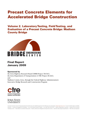
INTRODUCTIONFour-sided culvertsare typically referredto as box culverts.
INTRODUCTION Standard box sizes: 3’ x 2’ to 12’ x 12’in 1’ span and rise increments. Typically come in 6’ and 8’ lengths. Custom box sizes: Nonstandard sizingis permissible and must be designedper project design specification.
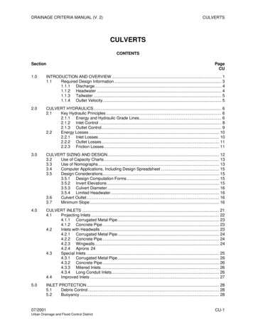
INTRODUCTION Three-sided structures are U-shapedstructures that may or may not have acrown in the center.
INTRODUCTION Standard three-sided structures rangefrom 8’ to 48’ span lengths. Custom sizes are available and mustbe designed per project designspecifications.
APPLICATIONSBox culverts Short-span bridges (over highways, waterways,railways, for golf courses, etc.) Conveyance of stormwater, sewage or industrialwastes (storm drains) Tunnels (to house conveyers, utilities, etc; to provideaccess, escape routes, etc.) DetentionThree-sided culverts Short-span bridges (flat and arched)
APPLICATIONSBenefits: Box culverts can be made in large sizes toaccommodate increased flow rates and capacities. Boxes can be set with 0 feet to 100 feet of cover.
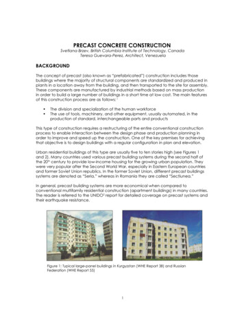
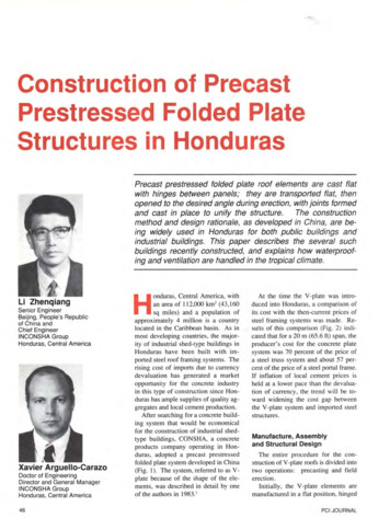
STORMWATER CONVEYANCETypical smallstream crossing.
TUNNELSFast andeconomicalmethod fortunnels underroadways, as inthis golf carttunnel.
TUNNEL & ESCAPE ROUTESProvide foremergencyegress, as withthis tunnelunderneath awarehouse anddistributioncenter.
STORMWATER DETENTIONMulticell boxculvertinstallation toeconomicallyprovidestorage ofstorm waterrunoff.
CUSTOM BOX SIZESCustomdesigned andmanufacturedbox culverts areavailable, aswith thismonolithic triplecell structure.
BENDS CAN BE DESIGNED
MITERS & SIDE OPENINGS
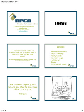
THREE-SIDED STRUCTURES Placed on stripfooting and used forshort span bridges. They allow fornatural stream bedsto remain intact andcan meet EPArequirements.
THREE-SIDED STRUCTURESLarge 3-sidedstructurew/precastheadwalls andwing walls.
SHORT-SPAN BRIDGESRoadway overroadwayapplications can beaccomplished withlong-span 3-sidedstructures.
MANUFACTURING METHODSWet-Cast Typically cast on end using an inner and outer form. Blockouts / hole formers can easily be incorporated. Cast with conventional concrete or self-consolidatingconcrete. Product cured in the form. Wet-cast is commonly used for sanitary applications.
MANUFACTURING METHODSDry-Cast (Machine Made) Product cast using mechanized equipment. Form vibrators consolidate zero-slump concrete betweencore and jacket. Hole formers may be incorporated, or coring is done asneeded. The product is immediately stripped and the form isreused. Products typically cured in a kiln, or a combination oftarps and moisture curing is used. Surface may appear textured due to manufacturingprocess.
DESIGN Designs are dependent on projectspecifications and applications. This includes hydraulic design for fluidconveyance structures.
DESIGNFluid Conveyance Hydraulic design and sizing are usually performedusing Manning's “n” for open channel flow(typical values for “n” are 0.012 for wet-cast and0.015 for dry-cast). This work is usually performed by the owner’sengineer, who then supplies the precaster with thesize requirements.
DESIGNStructural design is performed based onapplication After determining the size required, use applicablestandards for the box or three-sided structure design. This work is usually performed by the precaster or theprecaster’s engineer.
DESIGNList of common design standards: ASTM C 1433 – Box culverts, for conveyance ofstormwater, industrial wastes and sewage. ASTM C 1504 – Three-sided structures, forstormwater conveyance and culverts. AASHTO Standard Specification for Highway Bridgesfor short-span bridges.
DESIGNList of common design standards: ACI 318, for tunnels and special design. ACI 350R, for wastewater applications.
DESIGN – NOTES Box culverts are subject to: Lateral earth loads from soil and hydrostatic loadsfrom ground water. Vertical loads from the cover soil and live loadsabove. Surcharge loads from nearby impact loads. Seismic loads where applicable.
DESIGN – EXAMPLEBox culvert design for stormwaterconveyanceProject data:Flow rate, Q 1000 ft3/secLength, L 800 feetInitial slope, So 0.5%Allowable Head Water, HW 15 feetManning's, n 0.012
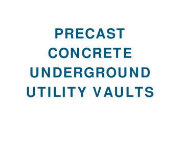
DESIGN – EXAMPLE After calculations, it was determinedthat a 9’ x 7’ box culvert will handle therequired flow. The box will supportHS20 loads: Use ASTM C 1433. Box to be set at 8’ depth, use table 1.
DESIGN – EXAMPLE9’ x 7’ x 9” CircumferentialReinforcement Areas, in2/ftDepth, ftAs1As2As3As4As5As6As7As8M0 20.250.580.290.220.220.220.220.222 250.510.880.900.2244
DESIGN – EXAMPLE
DESIGN – EXAMPLELess than 2’ Cover - 9’ x 7’ x 9”Circumferential Reinforcement Areas, in2/ftDepth, ftAs1As2As3As4As5As6As7As8M0 20.250.580.290.220.220.220.220.222 250.510.880.900.2244
DESIGN – EXAMPLE
JOINTS – EXTERNAL WRAP ASTM C 877
JOINTS – MASTIC/BUTYL ASTM C 990
JOINTS Closed cellular rubber (vinyl & nitrile elastomers). Physical properties of ASTM D1056 Type 2C-1 &chemical resistance requirements of AASHTOM198. Requires a joint gap. Soil tight only.
JOINTSFemale (groove) endMale (tongue) end
JOINTS
INSTALLATION Trench must remain dry during the installationprocess, dewater if necessary. Bedding must be compacted, set to grade andmeet specifications. Place groove end section first. Set subsequent boxes with the tongue end beingset into the groove to reduce bedding disruption.
INSTALLATION Backfill shall be placed uniformly on each side ofthe precast concrete box sections. The backfillmaterial to be placed, the percent of compaction,the depth of layers, etc., shall be as required bythe contract specifications.
QUALITY When purchasing andspecifying box or three-sidedprecast concrete structures,you should specify certifiedplants. NPCA Certification program.
HS20 loads: Use ASTM C 1433. . 25 0.51 0.88 0.90 0.22 44 20 0.42 0.72 0.74 0.22 44 15 0.34 0.56 0.59 0.22 44 10 0.25 0.41 0.43 0.22 49 3-5 0.22 0.28 0.30 0.22 54 2 3 0.25 0.46 0.32 0.22 59 0 2 0.25 0.58 0.29 0.22 0.22 0.22 0.22 0.22 Depth, ft As1 As2 As3 As4 As5 As6 As7 As8 M DESIGN – EXAMPLE Less than 2’ Cover - 9’ x 7’ x 9” Circumferential Reinforcement Areas, in2/ft. DESIGN .