Transcription
Modeling of Pressure Profiles in aHigh Pressure Chamber usingCOMSOL MultiphysicsPresented at COMSOL Conference 2012 BangaloreDr. P. Srinivasa Rao &Chamanooru Kartik ChandraIndian Institute of Technology Kharagpur
Points to be covered Introduction Significance of HPP system Design requirements for HPP system Design of cylindrical shell Modelling of cylindrical shell using COMSOL
Introduction Conventionalfoodsterilizationandpreservation methods often result in anumber of undesired changes in foods. HPP is a non-thermal food processing method It subjects liquid or solid foods, with orwithout packaging, to pressures between 50and 1000 MPa.
Introduction HP Processing has potential to replaceconventional heat induced sterilization andpasteurization processes. Need to develop and produce HPP equipmentfor Indian food processing sector
PROCESS DESCRIPTION In a HP process, the food product to be treated is placedin a pressure vessel capable of sustaining the requiredpressure (50-1000 MPa); the product is submerged in aliquid, which acts as the pressure-transmitting medium. Some pressure transmitting media used in a HP chamberinclude water, castor oil, silicone oil, sodium benzoate,ethanol and glycol. Industrial High Pressure systems are usually batchprocessing systems. The selection of equipment depends on the kind of foodproduct to be processed. Solid food products or foods with large solid particles canonly be treated in a batch mode.
PROCESS DESCRIPTION Liquids, slurries and other pumpable products have theadditional option of semi-continuous production If water is used as the pressurizing medium, itscompressibility must be accounted for; water iscompressed by up to15 per cent of volume at pressuresabove 600 MPa. Once the desired pressure is reached, the pump orpiston is stopped, the valves are closed and thepressure is maintained without further energy input. After the required hold time has elapsed, the system isdepressurized, the vessel opened and the productunloaded.
Significance Despite of many advantages, cost of highpressure processing is high, mainly due to costof HPP equipment. Import from overseas. This is an attempt to design an indigenoushigh pressure processing vessel which is heartof HPP equipment.
HPP equipment - components Pressure vessel Cylindrical shell Removable Head (cap) Nozzle Pressurization and decompression valvesVessel supportsHigh pressure pumpCooling / heating arrangementTemperature, pressure sensorsControl unit
ASME Codes The organization is known for setting codesand standards for mechanical devices Adopted worldwide for design and fabricationof pressure vessels For design and construction of boiler andpressure vessels - ASME section VIII, division 1and division 2
1. Maximum stress theory Both ASME Code Section VIII Division 1, andSection I use the maximum stress theory as abasis for design. The maximum principal stress is determinedapplying this theory
2. Maximum Shear Stress Theory Yielding will start at a point when themaximum shear stress at that point reachesone-half of the the uniaxial yield strength. Both ASME Code, Section VIII, Division 2 andASME Code, Section III, utilize the maximumshear stress criterion.
Lames equationCircumferential stress,Radial stress,Longitudinal stress,
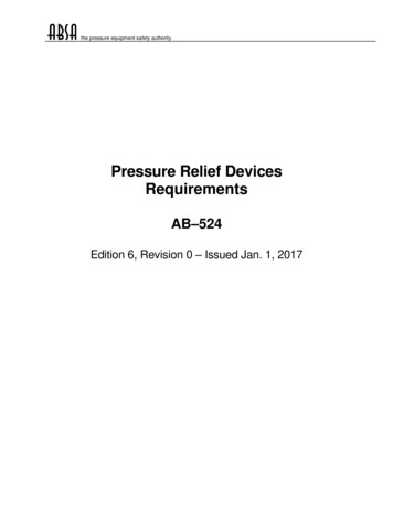
Fig. 1 Hoop and radialstresses in cylindrical shellFig. 2 Hoop and radialstress distribution incylindrical shell
Factor of safety Uncertainties in load, the dimensions, and thematerial properties. 62.5 percent of the yield strength at designtemperature European pressure vessel construction codestypically employ a factor of safety of 1.5 forthe yield strength for a simple environment .
Design requirements Operating pressure 500 MPaCapacity 0.5 litreTemperature range : 10 to 100 0CLoading – unloading : ManualIndirect compressionBatch type processFor 10 cm depth of the vessel, inside diameter of thevessel will be 8 cm.
Design of cylindrical shell Using ASME codes and Lames equation forcalculation of principle stresses.Sr. No.Thickness (m)σlong (MPa)σrad (MPa)σhoop (MPa)at riat ro10.04(ro 0.08)166.667500833.33333.3320.06( ro 0.1)95.2381500690.4762190.476230.08( ro 0.12)62.5500624.994124.99940.1( ro 0.14)44.444500588.88988.88950.11( ro 0.15)38.2775500576.5576.55
Dimensions of cylindrical shellInside diameter (Di)0.08 mThickness0.11 mOutside diameter (Do)0.3 mDepth of shell (l)0.1 mConsidering factor of safety of 1.5, required minimum yieldstrength of material to be selected should be 895 MPa
Slotted cylinder arrangement
COMSOL multiphysics Three dimensional finite-element analysissoftware which uses solid elements foranalysis. Import facilities for solid elements Different possible failures Accurate design assessment
METHODOLOGY An FEM analysis of a hollow cylinder, and the pressurevessel used for HPP was performed. Surface von Mises stresses were first modelled, after whichthermal stresses arising from the cylinder not being free toexpand and contrast to changes to temperature weremodelled together with the von Mises stress. Considering the compressive medium to be a fluid at 70 C,the changes in the temperature of the vessel with time wasmodelled. A general pressure vessel has an inlet at its bottom surfacefor the working fluid to enter the chamber. The top of the vessel has constrictions for the top cap toenter and lock into the constrictions. 5 constrictions havebeen placed on the vessel designed in this case.
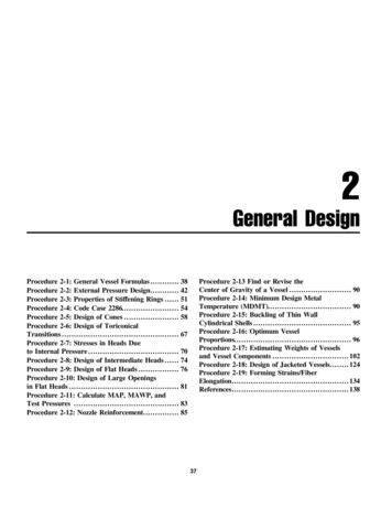
Stress distribution in cylindrical shell
Stress distribution in cylindrical shell
Stress in Screwed cylinder arrangement
Pressure Vessel (empty) – Geometry, Loading profile and fixed constraintsMesh and MeshStatistics
Stress Profile – EmptyPressure VesselStress Profile – EmptyPressure VesselInternalPressure(MPa)Maximumvon 400716.47450806.03500895.61
Empty Pressure Vessel – Pressure vs. Stress plot In the case of empty pressure vessel, the plot between the internallyapplied pressure and the maximum von Mises stress has been found to beessentially a linear plot. This is in accordance with the theoretical findingsof the plot in case of a cylinder under loading. The linear increase is attributed to the fact that the amount of expansiveforce on the surface has been increased leading to an increase in theprincipal stresses in the walls and consequently, in the magnitude of the vonMises stress. The linear increase results from the fact that within elastic range, therelation between pressure applied or stress applied results in a linearvariation of the strain produced in the vessel, in accordance to the Young’srelationship between stress and strain.
Pressure Vessel with polyethylene coreMesh generated
Pressure Vessel withpolyethylene core – LoadingProfile The loading surfaces in the pressure vessel are theinterior surfaces of the vessel and the outer surfaces ofthe polyethylene element. This is because according to Pascal’s Law, pressure istransmitted uniformly throughout the element whenplaced in a fluid medium. Hence, the pressure acts uniformly on the surface of thecylindrical element.
Stress Profiles – Surface von Mises and Thermal StressesThe thermal stresses are constant and do not change withtemperature because the temperature difference between theworking fluid and the surrounding temperature is the same underall the pressures taken in the above scenario.
Calculation of flux for Temperature – Time plots: Mass of water in the vessel 400 gSpecific Heat Capacity of water 4200 J/KgKHolding Time 120 sSurface Area of Polyethylene Core 2prL 2*p*0.02*0.085 0.010053096 m2 Flux (0.4L) x (1 kg/L) x (4200 J/kgK) x (5K)/[(120 s) x 0.010053096 m2] 6963.029101 W/m2
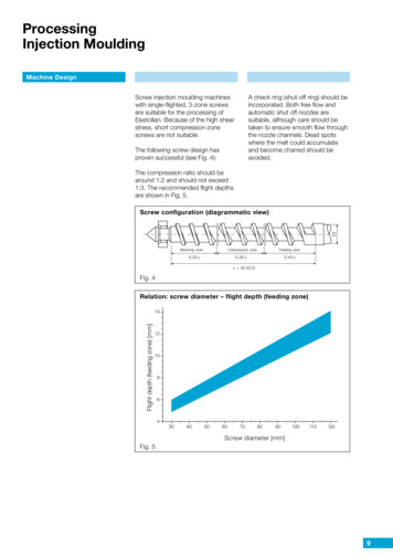
t 0t 30st 90st 60st 120s
From the temperature – time plots, it is clear that thetemperature of the vessel increases with time in the radialsense indicating the movement of a flux front with time,and also from bottom to up because the fluid entering ishotter than the surroundings and the inlet is closer to thebottom. Also, the maximum temperature of the vessel at the inletof the fluid increases with a falling rate as time passes bybecause the amount of heat absorbed by a hotter body islesser than when the same body were cooler. The system is assumed to be insulated from the outsidesufficiently to reduce the amount of heat dissipated. Thishelps in the temperature of the fluid falling back to itsoriginal inlet temperature after the processing of thematerial and the decompression of the system.
Conclusions If the system was perfectly insulated, the outlet andinlet temperatures of the working fluid would besimilar. However, such a system is purely theoretical,and insulation of such high standards is not practicallypossible. The variation of the temperature of the vessel with timehas been in accordance with its theoretical findings. Temperature of the vessel rose quickly at lowertemperatures and the rate of increase started to fall withtime. Also, temperature of the vessel increased radiallyoutward with a falling rate against time. COMSOL was found to be very useful tool for stressanalysis in such high cost equipment design.
References ASME Boiler and pressure vessel codes. 2007.Section VII- Div. 1: Rules for construction ofpressure vessel. ASME, New York Donatello A. 2007. Pressure vessel design, 1st Ed.Springer publishing, Italy. Chattopadhyay S. 2005. Pressure vessel: Designand practice. CRC Press, New Delhi. Khurmi R. S. and Gupta J. K. 2005. MachineDesign, Ch 7. Eurasia publishing house, NewDelhi. Moss D. 2004. Pressure Vessel Design Manual,Gulf professional publishing, USA.
Joe E. W. “Liquid pressure intensifier.” U.S. Patent1978/4097197. ASME. 2007. Rules for construction of pressurevessel. ASME code for pressure piping, B31,ASME B31.3-2002.
THANK YOU
Pressure Vessel Design Manual, Gulf professional publishing, USA. Joe E. W. "Liquid pressure intensifier." U.S. Patent 1978/4097197. ASME. 2007. Rules for construction of pressure vessel. ASME code for pressure piping, B31, ASME B31.3-2002. THANK YOU . Title: Design of high pressure processing vessel Author: H P .