Transcription
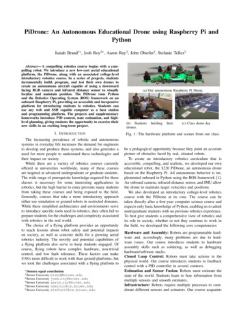
Published by :http://www.ijert.orgInternational Journal of Engineering Research & Technology (IJERT)ISSN: 2278-0181Vol. 10 Issue 09, September-2021PI Drone using PythonPrasant Chettri, Rajni Giri, Zerong Lepcha, Arvind LalDepartment of Computer Science and TechnologyCentre for Computer and Communication Technology (CCCT), Chisopani, Sikkim, IndiaAbstract - The drone is commonly known as Unmanned AerialVehicles (UAVs). In today’s world drone is extensively used inevery field, some of the common application of drone is nowbeing used for the Precision Agriculture, Search and Rescue,Wildlife Monitoring, Entertainment and others fields. As thewhole world was facing a fatal pandemic situation, dronesurveillance becomes an accommodating technology formankind. The drone brings a technology revolution to theglobal market. Drones are becoming profuse evolve technologyin today’s aeronautics, as like robotics. Every drone marketingcompany is focusing on AI (Artificial Intelligent) orautonomous flights system, but still, it requires humaninteractions. It was mainly controlled by remotes sensingtechnology, even with only hardware it is not possible to fly(UAVs) drones, we must necessitate its software andprogramming. The mathematical and physics law applicationmakes it possible for us to fly drones, but it is required muchaccuracy for stabilized hovering. Here we are using differentplatforms such as ROS, Linux, Gazebo (modelling orsimulating), Python, C , to develop obstacle avoidance andkeyboard control features in UAVs.Keywords- UAVs, Obstacle Avoidance, Lidar, SITL, EKF 2 ROS,GPS1. INTRODUCTIONUAVs is broadly appropriating in search and rescueoperations, military surveillance and civilian professionsbecause of their prominent advantages, such as flexibility,light mass, stable mobility, and good concealment.Nowadays, the growth and applications of UAVtechnologies only not change the evolving area of manyindustries but also brings market and economic benefits. Theautonomy level of UAVs varies according to the tasks athand or the degree to which the vehicle can make decisionswithout being explicitly guided by a remote operator.Usually, drones use various classification on-board sensorsthat can manage situational consciousness and autonomousdecision-making at run-time. Obstacle avoidance leads tothe approach of moulding the robot’s pathway to overcomeunforeseen obstacles. The resulting movement depends onthe drones’ existent position and the sensor interpretations.There is a level of algorithms for restriction avoidance frombasic re-planning to reactive rotation in the controllerstrategy. Advanced techniques vary on the execution ofsensor data and on the motion control approaches toovercome obstacles. The most generous difficulty ofautonomous drones is capable to react accurately and safelyto the circumstances during flight. Consequently, thesevehicles must be equipped with sensors proficient inrespondents very instantly and processing the systemintelligently interpreting all this data in real-time. This papercomprised III sections Hardware integration, Softwareintegration and Modelling & Avoidance Analyses. Thehardware platform used in this work is Raspberry pi &IJERTV10IS090105Navio2. In this, advanced environment ROS Gazebo is adynamic 3D simulated environment for autonomousvehicles that are especially suitable for examination (OA)systems. Gazebo used with Software in Loop(SIL) andHardware in Loop(HIL) design. These works are based onreal-time detection using an RP Lidar sensor and performingmodelled Lidar in a ROS gazebo simulation environment.Section C involves several embedded applications to processthe detection sensor to command the navigation, adorned inpragmatic conditions.A. System Hardware Architecture1) The Raspberry pi and Navio2 UAVs SystemAn autonomous drone requires at least two levels of controlto operate Inner Loop and Outer Loop. The Inner Loopstabilizes the vehicle at a desired angle or body motion. Aboard that controls the Inner Loop is a flight controllerNavio2 that allows pilots to communicate the requestedvehicle state, and output should stabilize commands to amotor to achieve that state. The Outer Loop generates anangle or rate of instruction to get the drone from point A toB. Raspberry Pi flight-controller is used to conducting allother outer loop control and request vehicle state to the flightcontroller. It is a decision making brain of a drone thatrequest, as performed by various on-board sensor data,combines and specific task it was carrying out. GPS datatells the flight computer where it is in space and about thewaypoint mission. The Navio2 eradicates several needs tobecome various controllers on board as everything iscompressed within one (including the Raspberry Pi),consequently enhancing the robustness of our project andexpediting the community. With the Navio2, we can controlour flying robots such as multirotor and planes. The Navio2is adorned with a High-resolution barometer double IMUand GNSS receiver with GPS, GLONASS, Beidou, Galileoand SBAS satellites for exact positioning and adjustment.The Navio2 is executing a data processing technique fornavigating to estimate the drone position and visualestimation. The method we are using for path planning andobstacle avoidance is SLAM (simultaneous localization andmapping) is a procedure used for an autonomous drone thatallows us to build a map and localize our drone to map in areal-time process. SLAM algorithm allowing the UAVs tomap out unrevealed environments. There exist differentSLAM methods but, we are working with the LiDAR SLAMsystem. Usually, LIDAR SLAM is used with a laser sensorto produce a 3D map of its environment. LiDAR (LightDetection and Ranging) estimates the range of an object bylocating the nearby object using an active laser 'pulse'. It isworking with a swift and accurate classification. So, it canwork in a comprehensive range of environments andconditions.www.ijert.org(This work is licensed under a Creative Commons Attribution 4.0 International License.)221
Published by :http://www.ijert.orgInternational Journal of Engineering Research & Technology (IJERT)ISSN: 2278-0181Vol. 10 Issue 09, September-2021to sensors and the relationship states to state timederivatives.X ki Fk (xki , uk ) eq(1)Yki Hk (xki , uk ) η eq(2)xki is a vector of a state that is estimated by the EKF, yk isa vector of the measurement and uk is the vector ofpredetermined inputs to EFK. η measurement noise vectorand ϵ state noise vector.The variance of error state using covariance matrix is followas Mk as shown in eq(3).TMk i [(xk xki )(xk xki ) ] eq(3)xk represent state vector which is the output of EKF. xki thisrepresents the expected relationship to the measurementprovided in equation (1) & equation (2), Mk is thecovariance matrix state in EKF method(d) Measurement UpdateFig 1. Hardware integration(a) Attitude and Heading Reference SystemAHRS works as a stabilization and motion control. Itcomputes a central processing unit (CPU) to the IMU, theAHRS features state algorithms for a wide range of dynamicmotions of UAVs. It comprises IMU 3-axis gyroscopes,accelerometers, and magnetometers that support wing,heading, pitch and roll data, also providing high-frequencyreal-time UAVs rotation data and open-ended gyroscopefixings. These sensors are attached to an external GNSSreceiver to enhance its execution. It implants the ExtendedKalman Filter that produces position and headinginformation.The process of updating the measurement vector yk is calledmeasurement update. This can be performed using theKalman gain matrix. Here, t is a current updateHkt Hk (xkt 1 , ukt )Gkt Mkt 1 HkTt (Hkt Mkt 1 HkTt Sk ) 1sk is the matrix of expected sensor noise of measurementand the Hk is the matrix that maps the states and input of anEKF to the measurement of the EKF methods, t-1 on tensorindicate using a value from previous (KF) update of thattensor. The KGM Gkt for this update is used to compute theupdate state estimate xkt and update Mkt as shown inequations (5)&(6).(b) Inertial Navigation System (INS)INS is a computer system that takes input from a globalnavigation satellite system such as GPS or InertialMeasurement Unit (IMU), which measures the PayloadStabilization & Orientation of the UAVs. The IMU outputsgyroscopes, accelerometers, and magnetometers raw data,and the Inertial Navigation System (INS) additionallyimplant a GNSS receiver for a clarified attitude in real-time.The inertial navigation system is a self-esteem processthrough which a system may track its attitude, orientationand velocity (once provided initial values for theseparameters) without the necessity of such outer implications.If the acceleration of an object is classified, it is probable touse numerical integration to estimate the velocity.(c) Extended Kalman Filter(EKF)EFK is the nonlinear version of the Kalman filter thatlinearizes the estimation of the current mean and covariance.This algorithm evaluates vehicle position, velocity andangular orientation based on rate accelerometer, gyroscope,GPS, airspeed and barometric pressure estimations. Thisnonlinear state-space model illustrates the relationship stateIJERTV10IS090105 eq(4)X kt X kt 1 Gkt [yk Mkt (I GkδHktδxktδHkδXkxkt 1 ] eq(5))Mkt )Mkt 1 eq(6)(e) Time UpdateThe state prediction update performed applying therelationship in equation (1) estimated for the time update.Equation (1) evaluating continuous, the time interval chosento balance the processor usage and estimator performance.In several statuses of discrete or continuous inputs, the timeupdate is executed many times between each measurementupdate. At each of those time updates, state estimation usesto predicted from the measurement relationship.xkt xkt 1 TsNFk (xt 1 , ut eq(7))The integration to estimate the state vector xkt appearmultiple times to reduce errors due to integration errors fromnonlinearities in the state propagation. The variable N inequation (7) is the total aggregate of redundancies Ts is thetime passed after the last measurement update. Essentially,www.ijert.org(This work is licensed under a Creative Commons Attribution 4.0 International License.)222
Published by :http://www.ijert.orgInternational Journal of Engineering Research & Technology (IJERT)ISSN: 2278-0181Vol. 10 Issue 09, September-2021there is position time between processor consumption andexecution of the time update.xkt Φkt,t 1 xkt 1Φk(t,t 1) eq(8)δFk (xkt ,ukt )where Φk(t 1,δxkt 1)Φk(t,t 1) I eq(9) eq(10)Φk state transition matrix in state vectorxk maps t 1 thevalue of one state to the next state t in the time update.Mkt Φk(t,t 1) Mkt 1 ΦkT(t,t 1) Q kQ k is the matrix that adjusts parameters that express thepredicted covariance of the state determined by equation (1)TδFk (xkt , uktTs δFk (xkt , ukt )([] Mkt 1 [] )Nδxkδxk eq(12) Mk(t 1) QkEquations (11) and (12) both are a form of updatingcovariance matrix. Updating the covariance matrix can beiterated to improve the estimation.The measurement to state relationship Hk2 in equation (2)is written here as equation (18).pnpevgHk2 (xk2 , uk2 ) eq(18)xva cos ψ wn vg cos x[ va sin ψ wn vg sin x ]0010 0000001 000δHk2 (xk2 , uk2 )0000 100 0010000δxk2 vvsinx00 cos x g10 a,LPF sin ψ vcosx[00 sin x g01 va,LPF cos ψ ] eq(19)a.The measurement of inertial velocities to ‘smooth’ the GPSmeasurements to resolve high-frequency estimates for thestates.Txk2 [pn pe vg x wn we ψ] eq(13)pn pe is the Inertial Earth position towards the North and Eastorigin at an initial position. vg The velocity of the airframe toground, x is zero wind sideslip if yaw angle is in same courseangle. wn ww is a component of wind velocity Vw in thedirection from the north and east. ψ is Yaw angle in degrees,First Euler angle.̂ k θ̂k pLPF qLPF rLPF vLPF ]T eq(14)uk2 [ϕEKF2 use only the GPS measurement, shown in equation(15).ypn,GPSype,GPSyv y g,GPS eq(15)Xgps0[ 0 ]Two Zero placed here corresponds to two 'pseudomeasurements' that this classification uses to represent themeasured wind in the north and east directions. The flightpath angle of the UAVs is zero that the wind has no verticalcomponent pseudo-measurements are associated parts of theEKF(k) states x and truth inputs u as shown.y5k2 0 Va cos ψ wn Vg cos x eq(16)IJERTV10IS090105flight path angle is zero in equation (20) & (21)ṗ n vg cos x eq(20)ṗ e vg cos x eq(21)(f) Second Order Extended Kalman Filter (EKF2)yk2 eq(17)Jacobin measurement update is in equation (19) eq(11)Mkty6k2 0 Va sin ψ we Vg sin xb.Relationship that wind and airspeed are constantequation (22) & (23)v̇ g(va cos ψ wn )( va ψ̇ sin ψ) va sin ψ we )(va ψ̇ cos ψ)vg eq(22) ψ qc.ẋ gvgsin ϕ̇cos θ rcos ϕcos θUAVs coordinated turnstan ϕ cos(x ψ) eq(23)Taking matrix to relationship with equation (1), generatedequation will be shown in equation (24)Fk2 (xk2 , uk2 )vg cos xvg sin x̂ a,LPF cos ψ wn )( v̂ a,LPF ψ sin ψ) (v̂a,LPF sin ψ we )(v̂a,LPF(vvgg tanϕcos (x ψ)vg00̂̂sin ϕcosϕq̂ r̂[cos θ̂cosθ̂ eq(24)Some of more equation that we use while using EKF2method.www.ijert.org(This work is licensed under a Creative Commons Attribution 4.0 International License.)223
Published by �δψ gvgInternational Journal of Engineering Research & Technology (IJERT)ISSN: 2278-0181Vol. 10 Issue 09, September-2021ψva,LPF (wn cos ψ we sin ψ)vggv2ggvg eq(25)̂ cos(x ψ) eq(26)tan ϕ̂ sin(x ψ) eq(27)tan ϕ̂ sin(x ψ) eq(28)tan ϕB. System Software Architecture1) Ardupilot & DroneKitArduPilot facilitates the production and adoption ofadvanced, autonomous UAVs in real-time for passiveadvantages communication between GCS, including GPSpositioning, battery status and other live erudition. Itprovides control algorithms for vehicles with robust sensorrecompense algorithms, filtering and tuning inclinations.Enabled command modes to implement in every standardvehicle: Guided, Stabilize, RTL, Land, Flip, Poshold etc.ArduPilot led to Advanced Configuration allows thecomposition of more high-level innovations of the firmwareand hardware peripherals. It implements a comprehensivesuite of tools suitable for almost every medium of vehicleand application. DroneKit-Python API enables us to buildcourseware that runs on an onboard companion computerand interface with the ArduPilot flight controller adopting alow-latency interconnection. The API interacts with vehiclesover MAVLink protocol, API primarily intended for use inonboard companion computers (to maintain high-levelperformance predicaments including computer vision, pathplanning, 3D modelling and more). It can similarly beadopted for the GCS, interacting with vehicles over atremendous latency RF-link.MAVLink to accommodate flexible connection betweencompanion computers with ROS and MAVLink enabledautopilots and GCS. The UDP broadcast used the processstage and switched to the GCS address. MAVROS supportsROS topics that can send commands, publishes telemetryandprovidesseveralservices.SET POSITION TARGET LOCAL NEDcommunication. Concedes frame target y,SET ATTITUDE TARGET communication. Concedesframe the target attitude /angular velocity and throttle level,SET POSITION TARGET GLOBAL INT.Concedesframe the target attitude in global coordinates (latitude,longitude, altitude) and flight speed.3) ROS (Robot Operating System) & GroundControl Station (GCS)Robot Operating System (ROS) is the framework thatproduces different packages, libraries and tools for us todevelop and reiterate code within robotics applications. Itprovides conventional OS assistance like hardwareabstraction, device operators, libraries, ingenuity, executionof commonly-used serviceability (communication withinprocesses), package management etc. It includes variouspackages for computing trajectory, conduct SLAMalgorithms or implements remote control. It can interactbetween Python and C nodes and build with a crosscollaboration concept. The project-based on ROS (1) LinuxNoetic Ninjemys framework with heterogeneity UbuntuFocal (OS) for UAVs multiple abstraction leveldevelopment. The GCS software implements anautonomous operation and high-level Flight DispositionCompiler that assists the operator to compose complicatedmissions in a simple strategy. It predominantly works on aground-based computer that is applied toward planning andoperating a mission. UAV ground control software willprovide a real-time image of the vehicle’s state andproviding the capability to improve our mission. The GCSmission planners are building around a 2D or 3D mapping,which in enrichment to altitude and topography may renderseparate erudition such as no-fly zones and temporaryrestraints. A telemetry player feature is possible that enablesadministrators to replay the mission for moreover insightsand interpretation.C. Integrated Software and Simulation1) SITL (Software in The Loop) & ROS-GazeboFig 2. Integrating heterogeneity platform with Ardupilot2) MAVLink & MavrosThe Micro Air Vehicles Link(MAVLink) is thecommunication protocol used to communicate between aGround Control Station (GCS) and an Autopilot. Thisprotocol mainly operates in ArduPilot Firmware andprovides robust innovations like controlling, monitoring,integrating within the Internet. It provides systems forrecognizing packet drops and allotting packetauthentication. The Mavros ROS package facilitatesIJERTV10IS090105SITL enables us to operate ArduPilot on our computersdirectly, externally any exceptional hardware. ArduPilotproceeding SITL gives us access to the extensive extent ofcommunity tools available for desktop C development,typically interactive debuggers, potential analyzers anddynamic analysis tools. Here we are operating with aheterogeneous interface of ArduPilot and Dronekit-Python.The simulator model we are using is Gazebo, a 3D dynamicsimulator that has the extended capability to precisely andefficiently simulate communities of robots in complexindoor and outdoor conditions. To obtain ROS integrationwww.ijert.org(This work is licensed under a Creative Commons Attribution 4.0 International License.)224
Published by :http://www.ijert.orgInternational Journal of Engineering Research & Technology (IJERT)ISSN: 2278-0181Vol. 10 Issue 09, September-2021among stand-alone Gazebo, an assortment of ROS packagesspecifiedgazebo ros pkgsimplementswrappersapproaching the stand-alone Gazebo. Gazebo pluginsprovide URDF models with more comprehensivefunctionality and join in ROS communications andassistance requests for sensor output and motor input.Building with Catkin workspace combines CMake macrosand Python scripts to implement some functionality on topof CMake's workflow, decreases code redundancy withGazebo. The demonstration of heterogeneity SITL,Simulator and GCS are shown in Figures (3) a & b.Fig 3. a) ROS-Gazebo Simulation with Mission PlannerUrepi (X) {11k2 obsti (dobsti (X, X0 )0,2if dobsti (X, X0 ) d0 ,1 ) , eq(30)if dobsti (X, X0 ) d0 ,d0Where dobsti (X, X0 ) is the insignificant distance from (X) toobstacle i, K obsti is the repulsive potential field constant. d0is the influence range of the repulsive potential field.3) LIDARObstacle avoidance obtains by appealing LIDAR data toimplement a two-dimensional Cartesian map. Theproposition uses to create the map of the conditionspreceding the pathway intended based on the map to enablethe drone or robot to navigate in the petitioned obstacle-freearea.b) ROS-Gazebo Simulation with QGroundControl2) The Obstacle Avoidance Repulsive Potential FieldMethodsThe repulsive potential sustains UAVs away from theobstacles, both those a priori apprehend or those recognizedby the UAV onboard sensors. The Repulsive Potential ishigher during the UAV is closer to interference and producesa decreasing magnetism when the UAV is far distant. TheLinear nature from the repulsive potential sustains UAVsaway from the intricacy, the repulsive potential proceedsfrom the sum of the Repulsive influence of all specificobstacles isUrep (X) Urepi (X) eq(29)iAn obstacle quite far from the UAV is not possible todeflect. Furthermore, the magnitude of repulsive potentialshould expand when the UAV approaches a nearer obstacle.To estimate for this consequence and to the spacesurrounded influence, a feasible repulsion potentialgenerated by an interference i isIJERTV10IS090105Fig 4: Scanning method of RPLIDAR Sensor2. CONCLUSIONThe Lidar adopted measures 360 distance points all of theraw laser points embodied in the polar coordinate system as{(𝑑𝑖 , 𝜃𝑖 ); 0 𝑖 359}, anywhere 𝑑𝑖 is the distancemeasured from the center of the observer UAV to the objectand 𝜃𝑖 the relative angle of the measurement. The acquiredLidar erudition gathered in vector (𝑑𝑖 , 𝜃𝑖 ), the storedinformation converting the infinity scan values that meansthat there is no obstacle corresponding the ray to themaximum extent power that could measure by the Lidar(𝑑𝑚𝑎𝑥 ). An object located (𝑑𝑚𝑎𝑥 ) the observer UAV will beignored. In real-time, Lidar insistence instantly transmits themax range value to object outside their operating range.Furthermore, it is also conceivable to utilize the standardsfiltering to eliminate noise from the Lidar data.www.ijert.org(This work is licensed under a Creative Commons Attribution 4.0 International License.)225
Published by :http://www.ijert.orgInternational Journal of Engineering Research & Technology (IJERT)ISSN: 2278-0181Vol. 10 Issue 09, September-2021Fig 5. Lidar obstacle avoidance view in ROS-Gazebo SimulatorThis paper presents a Platform including (Raspberry pi &Navio 2) procedure to experiment with the genuinesimulated conditions for UAVs autonomous navigation toestablish approaching data enactment and classification ofthe algorithm satisfied to hold the benefit of convenientreference. Therefore, the work is extended to improve theautopilot system using a distinct heterogeneity combinationof Software and Hardware. Simulation is implementingusing the ROS Noetic Gazebo (3D visualization and physicmodelling) plugins with various sensors combinations ofURDF files. Working with AHRS EKF 2 derivation,combine DroneKit-python and Ardupilot SITL for UAVattitude and orientation. The obstacle Avoidance or anAutonomous flight is obtain using LiDAR, where thealgorithm is build using the Repulsive Potential FieldMethod. Mission Planner & QGroundControl GCS has beenapplied here for achieving real-time navigation andtrajectory planning in this phase. We have additionallyimplemented python-TK for commanding UAVs usingkeyboard direction arrows.3.REFERENCES[1]Arning, Richard & Langmeier, Andreas & Stenzel, Erwin. (2007).UAV/UCAV NAVIGATION SYSTEMS - PRESENT ANDPOTENTIAL FUTURE.[2] Ribeiro, Maria Isabel. "Obstacle avoidance." Instituto de Sistemase Robótica, Instituto Superio Técnico (2005): 1.[3] García, Jesús, and Jose M. Molina. "Simulation in real conditionsof navigation and obstacle avoidance with PX4/Gazebo platform."Personal and Ubiquitous Computing (2020): 1-21.[4] Meyer, Johannes & Sendobry, Alexander & Kohlbrecher, Stefan &Klingauf, Uwe & Von Stryk, Oskar. (2012). ComprehensiveSimulation of Quadrotor UAVs Using ROS and Gazebo. 7628.400-411. 10.1007/978-3-642-34327-8 36.[5] Yang, Shishan & Baum, Marcus. (2016). Second-Order ExtendedKalman Filter for Extended Object and Group Tracking.[6] Kallapur, Abhijit & Salman, Shaaban & Anavatti, S.G. (2007).Application of Extended Kalman Filter Towards UAVIdentification. 10.1007/978-3-540-73424-6 23.[7] Valiev, Mukhammad, and Husan Kosimov. "International Journalof Recent Technology and Engineering (IJRTE) ISSN: 22773878." Locomotive Diesel Engine Excess Air Ratio Control Device8.[8] Ravankar, Ankit A., Abhijeet Ravankar, Yukinori Kobayashi, andTakanori Emaru. "Autonomous mapping and exploration withunmanned aerial vehicles using low cost sensors." InMultidisciplinary Digital Publishing Institute Proceedings, vol. 4,no. 1, p. 44. 2018.[9] Khan, Zubair Ahmed. "Obstacle Avoidance Methods in UAVs."PhD diss., 2019.[10] Chen, Shengyang, Han Chen, Weifeng Zhou, C-Y. Wen, andBoyang Li. "End-to-end UAV simulation for visual SLAM andnavigation." arXiv preprint arXiv:2012.00298 (2020).[11] Alborzi, Y., B. Safari Jalal, and E. Najafi. "ROS-based SLAM andNavigation for a Gazebo-Simulated Autonomous Quadrotor." In2020 21st International Conference on Research and Education inMechatronics (REM), pp. 1-5. IEEE, 2020.[12] Park, Jongho, and Namhoon Cho. "Collision avoidance ofhexacopter UAV based on LiDAR data in dynamic environment."Remote Sensing 12, no. 6 (2020): 975.IJERTV10IS090105www.ijert.org(This work is licensed under a Creative Commons Attribution 4.0 International License.)226
PI Drone using Python Prasant Chettri, Rajni Giri, Zerong Lepcha, Arvind Lal Department of Computer Science and Technology . B. Raspberry Pi flight-controller is used to conducting all other outer loop control and request vehicle state to the flight controller. It is a decision making brain of a drone that