Transcription
Preprints of the 21st IFAC World Congress (Virtual)Berlin, Germany, July 12-17, 2020LQG controller for the LEGOMINDSTORMS EV3 Gyroboy SegwayrobotTimothy H. Hughes Gareth H. Willetts Jakub A. Kryczka University of Exeter, Penryn Campus, Cornwall, U.K. (e-mail:T.H.Hughes@exeter.ac.uk). University of Exeter, Penryn Campus, Cornwall, U.K. (e-mail:ghw205@exeter.ac.uk) University of Exeter, Streatham Campus, Devon, U.K. (e-mail:jak222@exeter.ac.uk)Abstract: This paper details the development of a Segway robot demonstrator for undergraduate and Masters level systems and control courses based on the LEGO MINDSTORMS EV3robotics platform. The purpose of the demonstrator is to provide a physical and interactivedevice for explaining concepts that feature on many systems and control courses, notably:model-based control, linearisation, the Linear-Quadratic Regulator (LQR), pole placement, noiseamplification due to differentiation, reference following, Kalman filtering, and the principle ofseparation of estimation and control. The demonstrator is designed using a standard LEGOMINDSTORMS model from the Education EV3 core set—the Gyroboy. This is interfacedwith using the Simulink Support Package for LEGO MINDSTORMS EV3 Hardware. Referenceinputs can be provided from either a keyboard or an Xbox One gamepad. To the best ofour knowledge, this is the first example of the successful implementation of an observerbased reference-following feedback controller for a Segway robot built entirely using LEGOMINDSTORMS EV3 components, with previous designs being either not observer-based orbased on the now outdated LEGO MINDSTORMS NXT platform.Keywords: Linear-Quadratic-Gaussian control, Observer-based control, Control education,Model-based control, Linear-Quadratic Regulator, Pole placement, Kalman filter1. INTRODUCTIONone for each wheel, each of which contains an encoder thatmeasures the angle through which that motor has turned.The value of LEGO MINDSTORMS for the teachingof control and robotics has widespread recognition (see,e.g., Canale and Brunet, 2013; Basso et al., 2013; Villacrés et al., 2016; Kim, 2011; Cruz-Martı́n et al., 2012;Markovsky, 2012). To date, most of the educational applications of LEGO MINDSTORMS detailed in the literature have focussed on the second generation NXT kit,which was superceded in 2013 by the third generationEV3 model. The use of LEGO MINDSTORMS in highereducation is facilitated by the hardware interfacing capacities offered by the LEGO MINDSTORMS EV3 Supportfor Simulink package, which allows for controllers to bedesigned within MATLAB Simulink and then deployed directly to the LEGO MINDSTORMS EV3 intelligent brick.This also allows for data to be returned to the MATLABworkspace from LEGO MINDSTORMS sensors to informcontroller design and enhance the teaching experience.The developed demonstrator was integrated into a newthird-year course on the Mathematical Sciences degree atthe University of Exeter, UK, titled Dynamical Systemsand Control. The intention was to provide an interactivephysical demonstration of the key concepts introducedduring the course, to improve students’ engagement andtheir intuitive and conceptual understanding. The demonstrator also sought to develop students’ awareness of themethods’ limitations and the importance of consideringthe practical aspects of design alongside the theoretical.Moreover, the methods used to design the Gyroboy controller were mirrored in a simulation based courseworkexercise in MATLAB Simulink, whereby students’ understanding is reinforced through problem-based learning.This paper details the design of a reference-followingLinear-Quadratic-Gaussian (LQG) controller for the LEGOMINDSTORMS EV3 Gyroboy set. This is a two-wheeledSegway robot, comprised of the EV3 intelligent brick (themicroprocessor for the robot), a gyroscopic sensor for measuring the Gyroboy’s tilt velocity, and two electric motors,Copyright lies with the authorsSeveral authors have noted the positive impact of LEGOMINDSTORMS on student motivation and outcomes, (seee.g., Panadero et al., 2010; Cruz-Martı́n et al., 2012). Sincethe demonstrator described in this paper was developed fora new course, it is not possible here to assess the effectiveness of the demonstrator in improving outcomes, but wedo note that students assessed the module positively (witha mean score of 90% and a range of 77-100%).17523
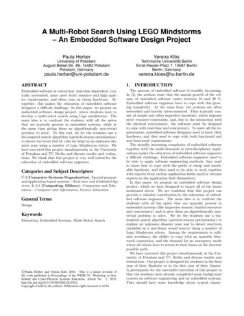
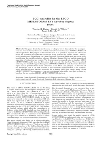
Preprints of the 21st IFAC World Congress (Virtual)Berlin, Germany, July 12-17, 2020In this paper, we describe the details of the demonstrator’sdesign, and its use in demonstrating model-based control, linearisation, the Linear-Quadratic regulator (LQR),pole placement, noise amplification due to differentiation,reference following, Kalman filtering, and the principleof separation of estimation and control. MATLAB andSimulink files, and videos of the design implemented onthe Gyroboy, have been made available by (Hughes et al.,n.d.). The merits of the demonstrator that make it standout relative to other teaching resources are its versatility(for demonstrating all of the aforementioned concepts),simplicity (the design only requires knowledge of controlconcepts that are commonly covered in undergraduateor Masters level courses, and the hardware interfacingcan all be carried out within MATLAB Simulink), andaffordability (the equipment cost is approximately 650).Applications of LQR, model predictive control, slidingmode control and fuzzy logic control to the stabilisationof LEGO Segway robots have previously appeared in theliterature (see Canale and Brunet, 2013; Villacrés et al.,2016; Yamamoto, n.d.; Akmal et al., 2017; Behera andMija, 2016). Our approach in this paper takes the LQRdesigns of Yamamoto (n.d.) and Roslovets (n.d.) as astarting point, and extends these designs in a number ofdirections. It is shown that the design of forward andturning motion controllers of the Segway robot can bedecoupled. Explicit expressions are provided for the controller gains as a function of the closed loop characteristicpolynomial, and pole placement is then used in order toimprove the forward motion by altering the fast dynamicsof the initial LQR design. Also, a Kalman filter basedobserver is implemented, based on an estimate of inputand output noise due to quantisation and other sensorerrors, and the resulting LQG controller demonstrates asubstantially smoother behaviour. Finally, the robot isdesigned to take reference inputs from either a keyboardor an Xbox One gamepad.2. OPEN LOOP DYNAMICSFollowing Yamamoto (n.d.), the open loop dynamics forthe Gyroboy can be described as a system with state vector dψdφ T,x θ ψ dθdt dt φ dtwhere ψ is the tilt angle (in radians); θ is the average ofthe two wheel angles (in radians), which depends on theangles θl and θr of the left and right motor through therelationship θ ψ 12 (θl θr ); and φ is the rotation angleabout the vertical (in radians), in accordance with Fig. 1.To obtain the moments of inertia Jφ and Jw , the depth ofthe Gyroboy robot is estimated as D 0.1m, and the massof the body and wheel is assumed to be evenly distributed,whereupon Jφ M (W 2 D2 )/12 and Jw (mR2 )/2.The motor calibration constants α and β correspond tocoefficients in a first order model of LEGO EV3 large servomotor’s dynamics. This motor takes integer inputs from-100 to 100, and α and β have units of kgm2 s 2 perinteger unit and kgm2 s 1 per integer unit, respectively.These parameters have been estimated by adding a thirdwheel to balance the Gyroboy, and then applying a stepinput to both motors of the Gyroboy. The dynamics of thissystem is then described by the differential equation d2 z2β dz2αuw(1)M 2m 2JR2dt2 R2 dt R .Here, u refers to the integer input to the motors, and zrefers to the horizontal distance of travel. The parametersα and β can then be estimated by applying a step inputof magnitude U 100 at time T0 1. By fitting astraight line to the steady-state behaviour of the cart, anddetermining the slope V of this line and the intercept T1with the time axis, then estimates for α and β that areconsistent with equation (1) are obtained as follows:β R2 (M 2m) 2Jw2(T1 T0 )and α 𝜃𝑙𝑀, 𝐽𝜓𝜙The estimation of these constants required only the LEGOMINDSTORMS EV3 sensors themselves, in addition to aruler and a pair of calipers (for measuring L, R and W ),and a set of gram-accurate weighing scales (for measuringm and M ). The remaining constants are then estimatedas follows. By measuring the time period of pendulumoscillations (T ) when the Gyroboy robot swings freelyabout the wheel axis, the moment of inertia Jψ can beestimated using the formula Jψ M L2 M gLT 2 /((2π)2 ).𝜙𝐽𝜙𝜃𝑙 , 𝜃𝑟𝑊𝜃𝑟𝑚, 𝐽𝑤Side viewβVRU .The correspondence between the experimental data andthe predictions of the fitted model are shown in Fig. 2.𝜓𝐿Estimates of the Gyroboy’s properties are as follows:m 0.031kg (wheel’s mass),M 0.641kg (body’s mass),g 9.81ms 2 (acceleration due to gravity),L 0.107m (distance from wheel axis to centre of mass)R 0.027m (wheel radius),Jw 1.13 10 5 kgm2 (wheel’s moment of inertia),Jψ 2.77 10 3 kgm2 (body’s pitch moment of inertia),W 0.105m (body’s width),Jφ 1.12 10 3 kgm2 (body’s yaw moment of inertia)α 0.505 10 3 (motor calibration constant),β 3.58 10 3 (motor calibration constant).Top viewFig. 1. LEGO MINDSTORMS EV3 Gyroboy schematic.Fig. 2. Motor calibration experiment.17524
Preprints of the 21st IFAC World Congress (Virtual)Berlin, Germany, July 12-17, 2020To model the Gyroboy’s dynamics, we letu1 12 (vl vr ), u2 12 (vr vl ), q1 u1 w1a and q2 u1 w2a .Here, vl and vr are the desired inputs to the left andright motors, respectively. Also, w1a and w2a correspondto quantisation and saturation errors, which arise as themotors only accept integer inputs between 100 and 100.Then, with the notationγ1 M gL, γ2 M LR, γ3 2Jw (2m M )R2 ,γ4 M L2 Jψ , and γ5 M L2 ,the dynamics of the Gyroboy robot satisfy the equationdxdt f (x, z1 , z2 ), where f (x, z1 , z2 ) takes the formT[f1 (x) f2 (x) f3 (x, z1 ) f4 (x, z1 ) f5 (x) f6 (x, z2 )] ,with f1 (x) dθdt ,dφf2 (x) dψdt , f5 (x) dt , 2 2γ2 sin(ψ) γ4f3 (x, z1 ) dψdt γ1 cos(ψ) γ5 cos2 (ψ)γ γ4 γ22 cos2 (ψ) 2 αz1 β 3dψ dθdt dt γ3 γ4 γ222 γ3 sin (ψ) γ1 γ5 dφdtf4 (x, z1 ) (γ4 γ2 cos(ψ)),cos2 (ψ) 2 cos (ψ) γ22 sin (ψ) cos (ψ)dψdtγ3 γ4 γ22 cos2 (ψ) f6 (x, z2 ) dφdt dψ dθ2 αz1 β dt dt γ3 γ4 γ22(γ3 γ2 cos(ψ))cos2 (ψ)3. CONTROLLER DESIGN, andW 2 dφW2 dψ dφR αz2 2R2 β dt 2M L dt dt sin (ψ) cos (ψ) .W2mW 2222 Jφ 2R2 Jw M L sin (ψ)The derivation of these equations follows Yamamoto(n.d.). The motor’s moment of inertia has been omitted asit is negligible in comparison with the body pitch and bodyyaw moments of inertia, so the error due to its omission isdeemed insignificant relative to other model errors.By partitioning the system’s states into the forward statesx1 and turning states x2 thus, T dψ Tx1 θ ψ dθand x2 φ dφ,(2)dt dtdtand by linearising this system about the equilibrium pointat the origin, we obtain an approximation for the dynamicsof the LEGO Gyroboy robot of the formdx1(3)dt A1 x1 B1 (u1 w1a ) anddx2dt A2 x2 B2 (u2 w2a ), where 0010 0001 A1 0 γ1 γ2 2 2β(γ2 γ24 ) 2β(γ2 γ24 )γ3 γ4 γγ3 γ4 γγ3 γ4 γ 222β(γ2 γ3 )γ3 γ4 γ2222 γ3 ) 2β(γγ3 γ4 γ22iT2α(γ2 γ3 )2α(γ2 γ4 ) ,22γ3 γ4 γ2γ3 γ4 γ2γ1 γ3γ3 γ4 γ22and (Basso et al., 2013, Sec. III)). Following some experimentation, the following procedure was found to effectivelycompensate for these effects. First, the offset is estimatedin an initial calibration phase, in which the Gyroboy issupported upright. This offset is subsequently subtractedfrom the gyroscopic sensor measurement. Moreover, tocorrect for calibration errors in this offset, the resultingsignal is passed through a (discrete-time) high-pass filterwith a time constant of 10 seconds. Finally, to compensatefor drift, the resulting signal is integrated and passedthrough a further (discrete-time) high-pass filter with thesame time constant, thereby providing an estimate forthe tilt angle (in radians). 1 We then take as forwardoutput y1 a vector whose first entry is the average wheelangle estimate (θl θr )/2 (in radians), and whose secondentry is the tilt angle estimate from the filtered gyroscopicsensor measurement. Also, as turning output y2 we takeRthe estimate for the turning angle W(θr θl ) (again inradians). These outputs then satisfy the relationshipsy1 C1 x1 w1b and y2 C2 x2 w2b(9)where w1b and w2b are disturbances due to sensor noise, 1 1 0 0, and C2 [1 0] .(10)C1 0 1 000hB1 0 0#"012, andA2 βW0 2Jφ R2 (mR2 J )W 2whiT2RαWB2 0 2Jφ R2 (mR.2 J )W 2w(4) , (5)(6)(7)(8)There are three sensors on the Gyroboy: the gyroscopicsensor measuring tilt angular velocity, and an encoder oneach of the two wheels measuring the two motor angles θland θr . The gyroscopic sensor exhibits a steady-state offsetand can drift (see e.g., (Canale and Brunet, 2013, Sec. IID)In this section, we present the stages in the design ofan observer-based reference-following feedback controllerin an incremental manner that can be followed in anundergraduate control systems course. We first present areference-following proportional controller for the turningmotion. Subsequently, we present the development of theforward motion controller, which illustrates the concepts ofLQR, pole placement, noise amplification due to differentiation, Kalman filtering, and the principle of separationof estimation and control. The final design comprises areference-following LQG controller that accepts referenceinputs from either a keyboard or an Xbox One gamepad.3.1 TURNING MOTION CONTROLLERThe turning motion of the Gyroboy is an example of a second order system that can be stabilised using proportionalfeedback. The error w2b in the estimate of the turn angley2 in equation (9) is dominated by quantisation errors inthe motor encoders, which measure motor angles to thenearest degree, and is sufficiently small to be neglected.Similarly, the motor quantisation error w2a in equation (4)will also be neglected. The open-loop turning dynamics arethen approximated in the vicinity of the upright equilib2rium point by the two-state system dxdt A2 x2 B2 u2 , dφ Twhere x2 φ dt , and A2 and B2 are as given inequations (7) and (8). It is easily verified that this model ofthe open loop turning dynamics is marginally stable due tothe presence of a simple eigenvalue of A2 at the origin. The1It should be noted that this filtering method is only effective in thisapplication as an adequate controller will maintain a small tilt angle.An alternative controller was also successfully implemented that usedthe calibrated but unfiltered gyroscopic sensor measurement. For thiscontroller, the angle estimate from the gyroscopic sensor drifted overtime, and feedback was required on the integral of the motor angleto prevent this from causing the Gyroboy’s location to drift.17525
Preprints of the 21st IFAC World Congress (Virtual)Berlin, Germany, July 12-17, 2020system can be stabilised using the proportional controlu k(φ φref ), leading to the closed loop dynamics: 01dx20 2RαW k βW 2 x2 2RαW k φref ,dt where 2Jφ R2 (mR2 Jw )W 2 .It can be verified that this model of the turning dynamicsis stabilised for any given k 0. The sum of the eigenvalues of the closed loop A matrix is given by its trace( βW 2 / ), and is independent of k, hence the fastestpossible response of the linearised closed loop system willoccur when the real part of these eigenvalues is equal to βW 2 /(2 ). The value of k for critical damping can thenbe obtained as k β 2 W 3 /(8Rα ).This is then implemented on the Gyroboy (together witha stabilising controller for the forward motion, as will beconsidered in Subsection 3.2). Fig. 3 shows the response ofthe Gyroboy when the reference signal φref is ramped upfor 5 seconds, held constant for 5 seconds, then rampedback down to zero. Note that the Gyroboy’s responseto the reference signal is slower than expected from themodel, owing in part to the coupling between the turningand forward dynamics in the real system.to be implemented on a sampled data system, and thestate and input penalties are specified as Q C1T C1 andR 0.01. Thus, this LQR controller penalises deviationsin the mean angle of the two motors, the Gyroboy’stilt angle, and the average input applied to the twomotors. Moreover, the penalty corresponding to a motorinput of ten LEGO units is equivalent to the penaltycorresponding to a deviation in mean motor angle, or intilt angle, of one radian. This results in the controller gainmatrix K [ 9.83 913 17.2 100], which providesthe forward motion control law u1 K(x1 xref ). Theexperimental results from implementing this controller onthe Gyroboy robot are shown in the top half of Fig. 4. Itcan be seen that the mean wheel angle successfully tracksthe reference. However, the tilt angle measurement andthe motor input u1 are very noisy, resulting in occasionalsaturation of the motor. Note that this LQR controllercan be improved through further fine tuning, to providestudents with an appreciation of heuristic methods forassigning the state and input penalty matrices Q and R.Pole placement The LQR controller has given a goodstarting point for the controller design, but as the systemhas only a single input it is possible to obtain an explicitexpression for the closed-loop characteristic equation toexamine the relationship between the controller gains andthe closed-loop pole locations as follows.The closed-loop poles for the linearised model of theGyroboy’s forward motion are the eigenvalues of A1 B1 KLetting K [k1 k2 k3 k4 ], then the following expressionfor the closed-loop characteristic polynomial is obtained:Fig. 3. Experimental and simulation data for the turningmotion of the Gyroboy.s4 2((γ2 γ4 )(αk3 β) (γ2 γ3 )(αk4 β)) 3sγ3 γ4 γ223 β)2 γ3 )αk2 γ1 γ3 21 k1s 2γγ13(αks γ2αγ 2(γ2 γ4 )αk1γ 2(γ22.γ4 γ 23 γ4 γ3 γ4 γ222By equating this to the general quartic function s4 a3 s3 a2 s2 a1 s a0 , we obtain four linear equations relatingk1 –k4 to a0 –a3 , which can be solved to give3.2 FORWARD MOTION CONTROLLERThe forward motion of the Gyroboy is modelled by thefour state system in equation (3), whose state vector isas in equation (2), and where A1 and B1 are as givenin equations (5) and (6). The measured forward outputsy1 then take the form of equation (9). To begin with,we neglect the noise terms w1a and w1b , whereuponθ [1 1] y1 and ψ [0 1] y1 . We subsequently usediscrete differentiation to estimate the remaining forwarddψstates dθdt and dt . A discrete low pass filter is applied tothe differentiated signals with a time constant of 8ms,which is sufficiently fast as to not interfere with therobot’s dynamics. Despite this filtering, this still resultsin particularly noisy state estimates (especially for dψdtand dθdt ), and noisy motor inputs, which are improvedsubsequently through the use of an observer.LQR As a starting point, an LQR controller is designed.Here, we let Q R4 4 denote the state penalty andR R denote the input penalty, so in the absence ofany referenceR signal the LQR controller will minimise the integral 0 (x1 (t)T Qx1 (t) u1 (t)T Ru1 (t))dt for thelinearised model of the Gyroboy forward motion (see,e.g., Åström and Murray, 2008, Sec. 6.3). The controlleris designed using the MATLAB lqrd command as it isk1 a0 (γ3 γ4 γ22 ),2αγ1k3 k2 a1 (γ3 γ4 γ22 ) β α2αγ1 ((γ3 γ4 γ22 )(γ1 a2 (γ2 γ4 )a0 ) γ12 γ3 ),2αγ1 (γ2 γ3 )2& k4 (γ3 γ4 γ2 )(γ1 a3 (γ2 γ4 )a1 )β.α 2αγ1 (γ2 γ3 )These relationships can be used for a detailed study ofthe sensitivity of the pole locations to variations in theparameters, and to compute theoretical limits on thecontroller gains for stability. In particular, one of the issueswith the LQR controller is the large amount of noiseamplification owing to the relatively high controller gains.One effective method that improves this is to slow downthe fastest pole of the LQR controller. Specifically, thelocations of the closed-loop poles of the LQR controllerare 54, 7.9, 5.5 and 1.4. By moving these to 30, 7.9, 5.5 and 1.4, it is found that the controller gainsreduce to K [ 3.65 591 12.7 58.0]. This resultsin a smoother behaviour. The experimental results fromimplementation on the Gyroboy are shown on the rightof Fig. 4. Relative to the LQR controller (on the leftof that figure), the motor input is less noisy and rarelysaturates. This is at the expense of slightly more overshootin response to a reference input in mean wheel angleθ, and larger amplitude oscillations in wheel angle whenthe robot self balances while stationary. Nevertheless, themotor input remains very noisy, due primarily to noise in17526
Preprints of the 21st IFAC World Congress (Virtual)Berlin, Germany, July 12-17, 2020dθψ and the estimates of dψdt and dt . We look to improve thisnext by implementing an observer.gyroscopic sensor output when the Gyroboy is stationary.The resulting signal does not closely resemble zero meanwhite noise and is dominated by low frequency noise (seethe left-hand side of Fig. 5). Such low frequency noiseis usual due to gyroscopic sensor offset and drift, anddoes not have significant adverse effects on the controller’sperformance. We therefore adjust the high-pass filters inthis experiment to have a time constant of 0.1s to reducethis low frequency noise, resulting in the signal on theright-hand side of Fig. 5. The power spectral density of thisfiltered signal is then computed, whereupon the followingpower spectral density estimate is obtained: 2 π 2 1024V .0 5 10 6180Fig. 4. Experimental results for the LQR controller (left)and pole placement controller (right).LQR with observer The previous controller iterations,which use discrete differentiation to estimate the systems’states, provide a clear illustration of the downsides ofnoise amplification due to differentiation. An order ofmagnitude estimate of the resulting noise can be obtainedby considering the errors due to quantisation, which arethen multiplied by the inverse of the sample time upondifferentiation, and subsequently by the controller gains,to show that this process causes jumps in the motorinput equal to a substantial proportion of the motorsaturation input. This is improved in this section throughthe implementation of a Kalman filter based observer.We recall that the forward motion of the Gyroboy ismodelled by the four state system in equation (3), wherethe measured forward outputs y1 are as in equation (9).Here, w1a represents errors in the motor input whichare predominantly due to quantisation and saturation;the first entry in w2a represents error in the estimate ofthe average wheel angle, which is predominantly due toquantisation; and the second entry in w2a represents errorin the estimate of the tilt angle, which is due to errorsin the filtered gyroscopic sensor measurement. A Kalmanfilter is then designed to estimate the forward state x1for this system. This assumes that the signals w1a andw2a correspond to zero mean white noise with associatedpower spectral densities W and V , respectively.We observe that the motors do not saturate, so the error inw1a is due to quantisation only, and W can be estimatedby calculating the variance of the quantisation error. Asthe desired forward motor input is the average of vl andvr , each of which is quantised to the nearest integer, thenwe obtain the power spectral density estimate W 1/24.Similarly, the first entry in w2a is predominantly dueto quantisation. This is the error in the average of thewheel angles, each of which is quantised to the nearestdegree, whereupon we estimate its power spectral densityas π 2 /(24 1802 ). The power spectral density for thesecond entry in w2a is estimated by measuring the filteredFig. 5. Noise on tilt angle measurement. The left-handfigure uses the regular high-pass filters with timeconstants of 10s (as implemented in the controllersthemselves). In the right-hand figure, the time constants have been adjusted to 0.1s.The Kalman filter provides an observer for the systemwhose state estimate x̃1 minimises the power spectraldensity of the state estimate error x1 x̃1 (see, e.g., Åströmand Murray, 2008, Sec. 7.4). For implementation on theLEGO MINDSTORMS intelligent brick, it is necessary toinstead use a discrete time analogue to the continuous timeKalman filter, which can be obtained using the MATLABcommand kalmd.The forward motion input is then specified as u K(x̃1 xref ), where K is the gain matrix corresponding tothe LQR controller obtained in subsection 3.2.1, to obtaina reference following LQG controller due to the principleof separation of estimation and control (see, e.g., Åströmand Murray, 2008, Sec. 7.3). The experimental results areshown in Fig. 6. The resulting behaviour of the Gyroboyis considerably smoother. However, there is notably morevariation in the error of the mean motor angle (θ) particularly when the Gyroboy is rotating (at around 50s),owing to the coupling between the nonlinear forward andturning dynamics. Note that the state estimates follow theactual measurements very closely for both the mean wheelangle θ and tilt angle ψ. Also, the noise on the motorinput is substantially reduced relative to the LQR and poleplacement controllers in Fig. 4, owing to the estimates fordψthe states dθdt and dt being considerably smoother.3.3 REFERENCE INPUTA reference input is provided to the Gyroboy observer T for the foras a state reference xref θref 0 dθdtref 02The estimation of the bottom right entry in V is somewhatheuristic since the corresponding signal is poorly approximated aswhite noise. However, a good performance was observed for a rangeof values.17527
Preprints of the 21st IFAC World Congress (Virtual)Berlin, Germany, July 12-17, 2020Fig. 6. Experimental results for the LQG controller.ward motion and a turning angle reference φref for theturning motion. The reference inputs used in the experiments presented in this paper were pre-programmed,but user control has also been implemented using a keyboard and an Xbox One gamepad. In each case, theresulting signal is sent to the Gyroboy using UDP sendand UDP receive blocks. A MATLAB function blockthen contains the logic to convert these into velocityreferences from which the state references are subsequently computed. In the case of keyboard control, thekeyboard presses are logged in Simulink using the Sfunction sfun keyboard input v1 01 of Compere (n.d.).For Xbox One control, the gamepad interfaces withSimulink through a Gamepad Simulator block from theSimulink Coder Support Package for ARM Cortex-basedVEX Microcontroller, and is compatible with a standardWindows PC using either a USB or Bluetooth connection.4. CONCLUSIONS AND EXTENSIONSWe presented an LQG controller for a Segway robot basedon the standard LEGO MINDSTORMS EV3 Gyroboymodel. This provides physical and interactive demonstrations of concepts typically taught on undergraduate andMasters level systems and control courses: model-basedcontrol, linearisation, LQR, pole placement, noise amplification due to differentiation, reference following, Kalmanfiltering, and the principle of separation of estimationand control. Hardware interfacing is carried out throughMATLAB Simulink, and the Gyroboy model also providesa platform for exploring further control and robotics applications in research or teaching projects. For example,collision avoidance can be implemented using the LEGOMINDSTORMS ultrasonic sensors, or the Gyroboy can beused as a testbed for novel control algorithms.Basso, M., Innocenti, G., and Rosa, A. (2013). Simulinkmeets LEGO: Rapid controller prototyping of a stabilized bicycle model. in 52nd IEEE Conference onDecision and Control, Florence, Italy, 330–335.Behera, P.T. and Mija, S. (2016). Balancing of two wheeledinverted pendulum using SOSMC and validation onLEGO EV3. in First IEEE International Conferenceon Power Electronics, Intelligent Control and EnergySystems (ICPEICES-2016).Canale, M. and Brunet, S. (2013). A LEGO MINDSTORMS NXT experiment for model predictive control education. In 2013 European Control Conference(ECC), Zürich, Switzerland, 2549–2554.Compere, M. (n.d.).Simulink keyboard 3630simulink-keyboard-input. Accessed: 25/10/2019.Cruz-Martı́n, A., Fernández-Madriga, J., Galindo, C.,González-Jiménez, J., Stockmans-Daou, C., and BlancoClaraco, J. (2012). A LEGO MINDSTORMS NXTapproach for teaching at Data Acquisition, Control Systems Engineering and Real-Time Systems undergraduate courses. Computers & Education, ).Lego Mindstorms EV3 e/71872lego-mindstorms-ev3-gyroboy. Accessed: 25/10/2019.Kim, Y. (2011). Control systems lab using a LEGO MINDSTORMS NXT motor system. IEEE Transactions onEducation, 452–461.Markovsky, I. (2012). Dynamical systems and controlmindstorms. In Proceedings of the 2012 20th Mediterranean Conference on Control & Automation (MED),54–59.Panadero, C.F., Román, J.V., and Kloos, C.D. (2010). Impact of learning experiences using LEGO Mindstorms Rin engineering courses. In Proceedings of the IEEEEDUCON Education Engineering 2010 – The Future ofGlobal Learning Engineering Education, 503–512.Roslovets, P. (n.d.).Gyroboy - self-balancingtwo-wheel robot (segway) based on Lego asedon-lego-ev3. Accessed: 25/10/2019.Åström, K. and Murray, R. (2008). Feedback Systems: AnIntroduction for Scientists and Engineers. Princeton.Villacrés, J., Viscaino, M., Herrera, M., and Camacho,O. (2016). Controllers comparison to stabilize a Twowheeled Inverted Pendulum: PID, LQR and Sl
based reference-following feedback controller for a Segway robot built entirely using LEGO MINDSTORMS EV3 components, with previous designs being either not observer-based or based on the now outdated LEGO MINDSTORMS NXT platform. Keywords: Linear-Quadratic-Gaussian control, Observer-based control, Control education,