Transcription
Cleaning System ManualOWNER’S MANUALFor PCC2000, PV3, Cyclean, Pool Valet,New Pool Valet, Vantage, Vanquish,StepClean, SwingSweep and EcoPool004-027-8742-00REV052313US and Foreign patents and patents pending –www.paramountpools.com/patents/295 East Corporate Place Suite 100 Chandler, AZ 85225Toll Free: 1.800.621.5886 Phone: 480.893.7607 Fax: 480.753.3397Paramount@1Paramount.com www.1Paramount.com1
TABLE OF CONTENTSCongratulations!. 3What You Need to Know. 3What is a Water Valve?. 4-5Unique Water Valve Features. 6Water Valve Parts Breakdown. 7Water Valve Instructions. 8-15How to Open the Water Valve. 8Module Installation (6-port). 9-10Module Installation (2-port, 3-port, 4-port). 11-12Alignment Guide . 13How to Close the Water Valve. 14Run/Pause Switch. 15Nozzles (Cleaning Heads). 16Nozzle Removal/Installation. 17-20Optional Paramount Debris Canister . 21Relationship with Pool Equipment. 22-25Cleaning Systems Powered by the Filter Pump. 22Cleaning Systems Powered by a Booster Pump. 23Filters. 23-24Valves for a single Pump System. 24Chlorinators, Tablet or Salt Systems, Ozone, Solar. 24-25Operating Instructions. 26Troubleshooting Guide for Paramount In-Floor Systems. 27-29Warranty Certificate. 30Copyright 2013 Paramount Pool & Spa Systems. All Rights Reserved.Contact Paramount Pool & Spa Systems at 1.800.621.58862
CONGRATULATIONSCongratulations on your new pool and thank you for choosing one ofParamount’s cleaning or circulation systems. This manual will addressall of Paramount’s systems, the PCC2000, PV3, Cyclean, Pool Valet,New Pool Valet, Vantage, Vanquish, Step Clean, Swing Sweep, and EcoPool. Your system may also include a Paramount debris canister andone or more of Paramount’s Drains (MDX-R3, MDX2, MDX, BuzztopChannel Drain and/or SDX).WHAT YOU NEED TO KNOWYour system’s performance will be maximized by adhering to the following operating instructions, and can be affected by seasonal weatherconditions that may require extended periods of operation. The cleaning performance directly relates to the type and design of your specificParamount system.It is recommended you call your pool builder or a professional servicecompany if your pool requires attention.3
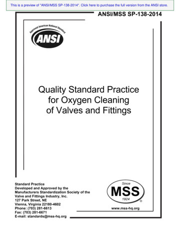
WHAT IS A WATER VALVE?The Paramount water valve is fullyautomatic and operates whenever thepump it’s connected to is running.Your Paramount Water Valve may beconnected to your filter pump or astand-alone “booster” pump.The water valve automatically distributes water to different areas of yourpool, which can include the floor, steps, benches, spa andwater features. It cycles much like an automatic sprinkler system in your yard switching from one circuit to another (Figure1 shows the combination of water valves). Every water valvehas a center port. This is where the water enters the valve.You will have a 2-port, 3-port, 6-port, 9-port or 12-port systemdepending on the design of your pool. The port count of thewater valve indicates the number of circuits that send waterback to your pool or to another water valve. Cleaning nozzlesor returns are placed at the end of the circuits.4
WHAT IS A WATER VALVE?(CONT.)Figure 12 PORT VALVEFROMPUMP3 PORT VALVEFROMPUMP6 PORT VALVEFROMPUMP9 PORT VALVE12 PORT VALVE12 PORT VALVE - 2 PORTSPECIAL VALVE PORTEDINTERNALLY TO FEED 3CIRCUTS THROUGH 1 PORT9 PORT VALVE - 4 PORTSPECIAL VALVE PORTEDINTERNALLY TO FEED 3CIRCUTS THROUGH 1 PORTFROMPUMPFROMPUMPCombination Water Valves (9-Port and 12-Port)A 9-port system consists of 2 water valves, a 6-port and a 4-port. The4-port valve has 3 circuits to the pool and 1 circuit that powers the6 port valve for a total of 9 circuits going to the pool. On this typeof system the 3 circuits on the 4-port valve fire twice as often as theother 6 circuits on the six port valve. Your system is designed specifically to take advantage of this firing sequence.A 12-port system consists of 3 water valves, two 6-ports and one2-port, 5 gear valve. The 2-port alternately powers each 6-port valve.Your system is designed specifically to take advantage of this firingsequence.5
UNIQUE WATER VALVE FEATURESThe run/pause switch on the top of the valve allows you to pause thesystem to isolate a circuit in an out of the way area of the pool.The one-piece replacement module design allows for easy installation.The gauge on your water valve is important and tells you how thesystem is operating. Gauges should be replaced when they becomeunreadable or inaccurate. Never use Teflon tape on a replacementgauge, use a thread sealant that is approved for plastic such asTeflon paste. Hand tighten gauge as over tightening can crack thewater valve lid.6
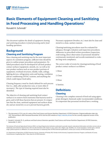
WATER VALVE BREAKDOWNFigure 2Top Dome CompleteIncludes Top, Gauge & Pause 4408-0022346Port 4 GearPort 5 GearPortPortPortBand Clamp CompleteIncludes Knob & Nut:005-302-3570-00Base O-Ring:005-302-0100-00Valve Base se1”1/21”1/21”1/21”1/2Valve Base se2”2”2”2”BlackBlackBlackBlackValve Base kBlackBlack*US 2” is equivelant to Australian 50 mm.Pressure Gauge:005-302-3590-00Band Clamp Nut:005-302-0640-00Pause Assembly (IncludesScrew Knob, O-Ring & Pawl)005-302-3502-00Band Clamp Knob:005-302-3600-00NOTE: Winterizing plug is for 2 inch and63 mm only.Winterizing Plug:004-302-1670-00 (Single)004-302-1672-00 (6 Pieces)For 1 ½ inch valve base use a standard #8winterizing plug.7
WATER VALVE INSTRUCTIONSHow to open the water valve1. TURN OFF ALL EQUIPMENT INCLUDING PUMPS.WARNING! FAILURE TO DO SO CAN RESULT IN INJURY ORDEATH.2. Remove the band clamp by turning the clamp knob or 7/16 inchnut counter-clockwise until it comes off the bolt. Then carefullypull the clamp away from the valve.3. Lift the top off the base being careful to not lose or stretch theo-ring.4. Remove the module by lifting up and out of the base.Note: the module is designed to seal inside the base so it mayrequire a side to side or rocking motion while lifting out. An easysolution is to turn the pump on and off quickly. CAUTION! DONOT APPROACH THE WATER VALVE WHILE THE THE LID ISREMOVED AND THE PUMP IS ON. FAILURE TO DO SO CANRESULT IN INJURY OR DEATH.5. Do not pull the module by the gear mechanism. This can result indamage to the module.8
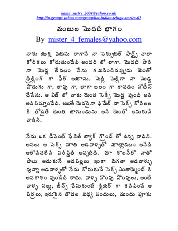
WATER VALVE INSTRUCTIONS(CONT.)Module Installation (6-port)1. Check the o-ring and groove for debris, and clean if necessary(this is a quad ring and is almost square, the height is slightly bigger than the width).2. Replace the o-ring (Part # 005-302-0100-00) if it is stretched ordamaged. The o-ring does not require any lubrication. Lubricatingo-ring can attract dirt and debris that could prevent it from sealing. Never use petroleum jelly on plastic or rubber parts, as thiswill damage them.3. Set the module in the base and turn until the alignment pins onthe bottom of the module drop into the alignment holes in thebase (Figure 3).4. The module should fit in the base without forcing it. If it does notseat easily then check the following. (Figure 3) shows the piston portion of the current moduledesign (released 06-2011). These pistons are set at thefactory. Do not touch, pull or turn these pistons. Any handlingwill negatively affect the performance and fit of this product. If the flow optimizer (Figure 4) prevents the module fromseating properly in the base you may have to remove it. Toremove optimizer press in on the 3 clips and pull to seperate.9
WATER VALVE INSTRUCTIONSFigure 3MODULE(BOTTOM VIEW)ALIGNMENT PINSSIDE VIEWPISTONSBASE(TOP VIEW)ALIGNMENT HOLESFigure 4(RELEASED 06-2011)10(CONT.)
WATER VALVE INSTRUCTIONS(CONT.)Module Installation & Alignment Guide (2-port,3-port, 4-port)1. Check the o-ring and groove for debris and clean if necessary(this is a quad ring and is almost square, the height is slightlybigger than the width).2. Replace the o-ring (Part # 005-302-0100-00) if it is stretched ordamaged. The o-ring does not require any lubrication. Lubricatingo-ring can attract dirt and debris that could prevent it from sealing.Never use petroleum jelly on plastic or rubber parts, as this willdamage them.3. The module should fit in the base without forcing it. If it doesn’tseat easily then check the following. 2-port module alignment – on the 2-port module the portson top of the module that are attached together by tubesmust be centered over the open ports in the valve base(Figure 5). 3-port module alignment – on the 3-port module the portson top of the module that are attached together by tubesmust be aligned over an open port and a closed port section (Figure 5). 4-port module alignment – on the 4-port module the portson top of the module that are attached together by a tube11
WATER VALVE INSTRUCTIONS(CONT.)must be aligned over the half of the base that has only oneport (Figure 5).4. Set the module in the base and rotate slightly back and forth untilthe alignment pins on the bottom of the module drop into thealignment holes in the base (Figure 3).5. The module should fit in the base without forcing it. If it does notseat easily then check the following. (Figure 3) shows the piston portion of the current moduledesign (released 06-2011). These pistons are set at thefactory. Do not touch, pull or turn these pistons. Any handling will negatively affect the performance and fit of thisproduct. If the flow optimizer (Figure 4) prevents the module fromseating properly in the base you may have to remove it.To remove optimizer press in on the 3 clips and pull toseperate.12
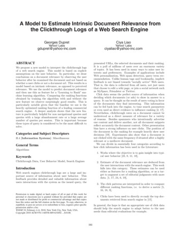
WATER VALVE INSTRUCTIONS(CONT.)Alignment GuideFigure 52 PORT / 4 GEAR // MODULE, BASE3 PORTUsed for basin & spa applications, Eco Systems & Swing SweepUsed for Eco Systems & Swing SweepModule Part# 004-302-4400-00Base Part# 005-302-4002-03 (2”)005-302-4006-03 (63mm)// MODULE, BASEModule Part# 004-302-4404-00Base Part# 005-302-4012-03 (2”)005-302-4009-03 (63mm)2 PORT / 5 GEAR // MODULE, BASE4 PORT // MODULE, BASEUsed on 12 port systems to feed the two 6 port valvesFound on 9 port systems - feeds 6 port valveModule Part# 004-302-4402-00Base Part# 005-302-4002-03 (2”)005-302-4006-03 (63mm)Module Part# 004-302-4406-00Base Part# 005-302-4018-03 (2”)005-302-4020-03 (63mm)6 PORT // MODULE, BASEModule Part# 004-302-4408-00Base Part# 005-302-4032-03 (2")005-302-4030-03 (1½")005-302-4038-03 (63mm)*US notation of 2” is equivalent to Australian 50 mm.13
WATER VALVE INSTRUCTIONS(CONT.)How to close the water valve1. Check the o-ring and groove for debris, and clean if necessary(this is a quad ring and is almost square, the height is slightly bigger than the width)2. Replace the o-ring if it is stretched or damaged. The o-ring doesnot require any lubrication. Lubricating The o-ring can attract dirtand debris that could prevent it from sealing. Never use petroleum3.4.5.6.7.jelly on plastic or rubber parts, as this will damage them.Place the run/pause switch in the run position then install thevalve top onto the base. The lid may be rotated in any directionfor easy viewing of pressure gauge.Place the band clamp around the valve shells and put the clampknob or 7/16 nut on the threaded bolt.Tighten the knob/nut securely. Note: Gently tap the band clampstarting opposite the knob/nut going around both sides. Whileperiodically tightening the knob/nut. Be careful not to over tightenthe knob/nut.Turn on the pump and inspect the water valve for leaks.CAUTION! NEVER stand over any pool equipment when startingthe pump after working on it.If you find leaks, turn off the pump and tighten the band clampmore. If it continues to leak, repeat the above steps. If this doesn’twork, replace the o-ring.14
WATER VALVE INSTRUCTIONS(CONT.)The Run/Pause control switchThe run/pause control switchis used to stop the cleaningsystem circuits from cycling.When switched to the pauseposition, it will stop on thecircuit that is up at that time.The run/pause control switchshould only be used when youdesire the nozzles not in theup position to remain down orwhile servicing the system.Figure 6Note: The run/pause control switch can be used without turningoff the pump, but can cause damage to the water valve or modulediaphragms if overused. If you frequently use the run/pause controlswitch you should turn off the pump first. Always turn the run/pausecontrol switch to the run position when removing and replacing thewater valve lid.15
NOZZLES (CLEANING HEADS)All Paramount nozzles are sized and placed specifically for yourpool by Paramount. These nozzles have different sized openings and if removed, should be returned to the same location.NOTE: Switching nozzle(s) location will result in poor cleaningand could severely damage your pool equipment.All of your system nozzles must extend and retract completely witheach cycle of the water valve. Depending on the cleaning system, itwill take 12 to 18 cycles for a nozzle to rotate 360 degrees. Thereare two exceptions to this.1. The PCC2000 and Vantage systems can have one to threenozzles (called Fixed Nozzles) that do not rotate and remain activewhile pool filter pump is on. These nozzles are located near themain drain and need to be aimed at the main drain.2. The optional Swing Jet nozzles are placed on the sidewall ofa pool, and rotate back and forth between three positions in a90-degree arc. They must retract and extend fully to move to thenext position.16
NOZZLE REMOVAL /INSTALLATIONNozzles may need to be removed from time to time for purposes ofwinterizing or to flush debris from the lines and/or nozzles. There are3 methods of removing the 8 different types of nozzles.Method 1:For Vanquish, Vantage and PCC2000 floor nozzles see Figure 7.Using the removal tool common to these nozzles, attach the tool tothe end of your pool pole placing it over the nozzle and making surethe tool tabs insert into the nozzle slots. Turn the tool clockwise a ¼turn to unlock the nozzle and then lift it from the body in the floor ofthe pool. When replacing the nozzle, be sure the body is free fromall debris or the nozzle will not lock in place. Make sure the o-ring onthe bottom of the nozzle is in place. Lock the nozzle into the tool onthe end of your pool pole and replace the nozzle in the body and turncounter clockwise to lock into the body.NOTE: Sand and pebbles can get between the body and the nozzleand make it very difficult to remove a nozzle. To make the nozzle removal easier, use a pressure nozzle on a garden hose (like you use toclean the side walk) and blow the debris out between the nozzle andbody before using the tool toFigure 7remove the nozzle.NOTE: The nozzle is specificto the body it came out of.Always put the nozzle back inthe same body it came out of.Part Number: 004-552-5440-00Part Number: Vantage 004-602-5440-00, Vanquish 004-577-5440-00, PCC004-552-5440-0017
NOZZLE REMOVAL /INSTALLATION (CONT.)Method 2:Some PCC2000 systems used the large floor nozzle in the steps.See Method 1 for removal and installations instructions.PV3, Cyclen and PCC2000 step nozzles see Figure 8. Using theremoval tool common to these nozzles, attach the tool to the end ofyour pool pole placing it over the nozzle and making sure the tooltabs insert into the nozzle slots. Turn the tool counter-clockwise a ¼turn to unlock the nozzle and then lift it from the body in the floor ofthe pool. Make sure the o-ring on the bottom of the nozzle is in place.When replacing the nozzle, lock the nozzle into the tool on the end ofyour pool pole and replace the nozzle in the body and turn clockwiseto lock into the body.NOTE: Sand and pebbles can get between the body and the nozzleand make it very difficult to remove a nozzle. To make the nozzle removal easier, use a pressure nozzle on a garden hose (like you use toclean the side walk) and blow the debris out between the nozzle andbody before using the tool to remove the nozzle.NOTE: The nozzle is specific to the body it came out of. Always putthe nozzle back in the same body it came out of.Figure 8Part Number: 004-627-5452-00Part Number: Cyclean 004-652-5452-00, PCC 004-552-5452-00, PV3 004-627-5452-0018
NOZZLE REMOVAL /INSTALLATION (CONT.)Method 3:Pool Valet (released in 1980) and Step Clean see Figure 9. Usingthe removal tool common to these nozzles, place the ends of theU-shaped tool in 2 of the slots and turn counter-clockwise. This is athreaded retainer ring that will require 3 full turns to remove. If you experience difficulty unthreading the retainer ring tap on it gently. Thisis best accomplished by tapping on the top of the tool. The amountof force necessary can vary depending on how long the nozzle hasbeen installed. When replacing the threaded ring of the nozzle wrap ittwice with Teflon tape. This will make for easy removal in the future.Turn it clockwise approximately 3 turns until it is snug in the body.NOTE: Sand and pebbles can get between the body and the nozzleand make it very difficult to remove a nozzle. To make the nozzle removal easier, use a pressure nozzle on a garden hose (like you use toclean the side walk) and blow the debris out between the nozzle andbody before using the tool to remove the nozzle.NOTE: The nozzle is specific to the body it came out of. Always putthe nozzle back in the same body it came out of.Figure 9Part Number: 004-502-5420-0019
NOZZLE REMOVAL /INSTALLATION (CONT.)Method 4:New Pool Valet (October 2012) Using the removal tool common tothese nozzles, place the tool in the 4 slots and turn counter-clockwise.This is a threaded retainer ring that will require 1 full turn to remove. Ifyou experience difficulty unthreading the retainer ring tap on it gently.When replacing the nozzle, snap the center of the nozzle into the toolon the end of your pool pole and replace the nozzle in the body, turning clockwise 1 full turn to lock into the body.NOTE: Sand and pebbles can get between the body and the nozzleand make it very difficult to remove a nozzle. To make the nozzleremoval easier, use a pressure nozzle on a garden hose (like you useto clean the side walk) and blow the debris out between the nozzleand body before using the tool to remove the nozzle.NOTE: The nozzle is specific to the body it came out of. Always putthe nozzle back in the same body it came out of.Figure 10Part Number: 004-502-5410-0020
OPTIONAL PARAMOUNT DEBRIS CANISTERYour pool may be equipped with the Paramount optional debriscanister, which would be located in the deck next to your pool. Thedebris canister is where the debris from your pool is gathered after itpasses through the drain. This debris needs to be emptied from thedebris canister’s catch basket/bag regularly. It is important to emptythe basket in the debris canister on a regular basis, just like yourskimmer and pump baskets, so your pool equipment will continue tooperate efficiently. This debris canister has a patented water sealedeasy to remove twist lock lid that needs no o-ring. The Paramountdebris canister’s water sealed lid has an equalizer running from thedebris canister to the pool to keep water on top of the lid. The equalizer line must be kept clear from obstructions.Paramount offers a high capacity stainless steel replacement basketfor your debris canister (Part # 005-152-8031-00).21
RELATIONSHIP WITH POOL EQUIPMENTCleaning Systems Powered by the Filter Pump1. Pumps must be capable of maintaining 20 psi (138 kPa) on thewater valve(s) pressure gauge.2. Your pump must be capable of maintaining 20 psi (138 kPa) atthe water valve regardless of the additional features on your poolsuch as spas, solar heating systems, heat pumps, water features,chlorinators, or any other device that is powered by your pump.3. Adding items to your filter system after construction (solar, heatpumps, water features, chlorinators, and any thing that takespressure away from the nozzles) will have a negative effect onthe cleaning system. Please contact your builder or Paramountbefore adding these items.4. Keeping filter clean is required to maintain the 20 psi (138 kPa) atthe water valve. A dirty filter will prevent your system from cleaningthe pool.5. The in-floor system comes with a pressure gauge on the watervalve and although the system may operate at lower psi, the bestcleaning results require 20 to 24 psi (138-165 kPa) at the watervalve pressure gauge. You will see reduced performance if thesystem is operated at less than ideal pressure.6. The systems cleaning cycle is determined by many factors (landscape, temperature, weather and condition of pool equipment).To determine your cleaning cycle, run the pool until it is clean. Inextreme conditions an extended cycle will be necessary.7. It is important to keep the skimmer and pump basket(s) empty, so22
RELATIONSHIP WITH POOL EQUIPMENT(CONT.)your pool equipment will power your in-floor system. Failure to doso will negatively affect the performance of your system.8. When cleaning your cartridge or D.E. Filter care must be takenbefore removing the filter elements that the filter tank be drainedand rinsed out. This is required to prevent dirt and debris fromentering the return line and getting into your in-floor system or anyother down-line components.Cleaning Systems Powered by a Booster Pump1. Because booster pump systems are designed to pull from theskimmer(s) and not use a filter, they are not affected by the typical reductions in performance that affect filter pump systems.Booster pumps need to produce a minimum of 65 gpm (246 lpm)at 60 ft. (179kpa of head).2. It is important to keep the skimmer and pump basket(s) empty, soyour pool equipment will power your in-floor system. Failure to doso will negatively affect the performance of your system.Filters1. A clean pool filter is necessary for optimum system performance.Your pool filter needs cleaning when filters pressure increases5 psi (34 kPa) above the pressure showing when your filter isclean.2. If the need arises to replace your filter and/or its backwash valveit is important that they are properly sized.23
RELATIONSHIP WITH POOL EQUIPMENT(CONT.) Sand Filter minimum size 4.9 square feet/.46 square meters D.E. Filter minimum size 48 square feet/4.5 square meters Cartridge Filter minimum size 200 square feet/19 squaremeters Backwash Valve minimum size 2 inch or 63 mm Europe Backwash Valve minimum size 2 inch or 50 mm AustraliaNOTE: Larger filter sizes will reduce the amount of cleaning needed.NOTE: Be sure your replacement filter is adequately sized for yourexisting pump.Valves for a Single Pump System1. The skimmer suction should be restricted to make the main drainpull more, because water takes the path of least resistance, andin-floor systems do most of their cleaning from the main drain2. Returns, spa over flows, and water features must be turned off orrestricted on single pump system so that the in-floor system willhave proper pressure. Minimum 20 psi (138 kPa) is needed torun the system.Chlorinators, Tablet or salt systems, Ozone unitsand Solar Systems1. Cells on salt chlorinators must be kept clean. Failure to do so willreduce the performance of your in-floor cleaning system.2. If you add a salt chlorinator after your pools construction it is24
RELATIONSHIP WITH POOL EQUIPMENT(CONT.)recommended to put cells on a bypass loop.3. Any device that uses a venturi injection system on the return sideof the filter is not recommended on single pump in-floor system.4. Solar systems on a single pump require a specific plumbingmethod, which includes a small booster pump for the solarsystem (Figure 11).Figure 11VACUUM SOLAR SENSORRETURNSFILTERPOOL PUMPPOOL SYSTEM25CLEANINGSYSTEM
OPERATING INSTRUCTIONS1. On all Paramount in-floor cleaning and circulation systems it isimportant to keep the skimmer, the pump and the debris canisterbaskets clean. It is also important to clean your filter when thepressure rises 5 psi (34 kPa) over the clean starting pressure.2. The gauge on your water valve is important and tells you howthe system is operating. Gauges can deteriorate over time andshould be replaced when they become unreadable or inaccurate.Never use Teflon tape on a replacement gauge, use a threadsealant that is approved for plastic such as Teflon paste. Handtighten gauges as over tightening can crack the water valve lid.3. If a nozzle is stuck open or up when the pump shuts off you mayclear it by pushing down on it a few times while pump is on toclear the obstruction.4. No cleaning system is 100%. Paramount’s in-floor guaranteeis the strongest in the industry but some attention to the pool isrequired to keep your backyard oasis beautiful. You must keepyour chemicals at proper levels, and brush any small areas thatmay have a build up of heavy sand or debris. Keep in mind thatwhen excessive debris gets into a pool, such as large amounts ofleaves in the fall or dirt during a dust storm, no cleaning systemcan do the job without some help, so be sure your equipment ismaintained.5. On PCC and Vantage systems that may have fixed nozzles theymay need to be adjusted to keep their flow of water aimed inthe direction of the debris drain. These nozzles can be turnedclockwise when in the up position by pushing down slightly androtating them towards the main drain.For further instructions see troubleshooting guide (pg 27-29).26
Troubleshooting Guide forParamount In-Floor SystemsProblemDiagnosisSolutionCleaningnozzles(s) arestaying up whenthe pump is offCleaning nozzles could bejammed with sand or debriswhich could result from impropercleaning of your pool filter. Seesection Paramount’s systemsrelationship to your pool’sequipment.Isolate the circuit of the jammedor stuck cleaning nozzles usingthe pause switch on your watervalve. With the system pumprunning push the cleaningnozzles down repeatedly withyour foot or pool pole.Cleaning nozzleson a circuit stayup once thewater valve hasswitched to thenext circuit butretract when thesystem is off.A circuit in the water valve isstaying open due to a jammedpiston in the module. Thiscould be caused by debrisentering the water valve.Remove the module from thewater valve (see module removalprocedure) clean it by holding itin the pool sideways and moveit back and forth quickly until itis clean. If there are any pistonsin the open position, push themshut being sure not to rotatethem. Place the module backin the water valve (see moduleinstallation procedure) and turnthe system pump on to determineif the cleaning nozzles are nowfunctioning properly. Dependingon the age of the module, if thisdoes not solve the problem itmay be time to purchase a newmodule.NOTE: PCC AND VANTAGEBOOSTER PUMP SYSTEMSMAY HAVE FIXED NOZZLESON THE FILTER PUMPWHICH STAY UP WHILE THEFILTER PUMP IS ON.It is always best to call a trained professional to service your poolFurther information on your cleaning system can be found at: www.1paramount.com27
Troubleshooting Guide forParamount In-Floor SystemsProblemDiagnosisSolutionSystem is notcleaning as itused to.Check for minimum operatingpressure of 20 psi (138 kPa) onthe water valve.Check the run time of your infloor system. It may need to beextended. Especially during increased demand due to weatherconditions or bather load. Referto the section titled Paramount’ssystems “relationship to yourpool’s equipment”. If after following these steps and the problemstill exists call a trained professional to service your pool.System is notcleaning as itused to.Pool drain is plugged.With the filter pump and boosterpump (if applicable) both runningadjust your valves on the filterpump to draw 100% from thepool drain. If your filter pump becomes noisy (cavitates) your pooldrain may be obstructed. At thispoint call a trained professionalto service your pool.An area aroundone nozzle thatis going up anddown is not beingcleaned.Cleaning nozzle is partially orcompletely blocked.Refer to the Nozzle/Installationand Removal section. Removethe nozzle. With the nozzle removed turn on the system pumpto blow out the circuit. Checkthe nozzle for debris stuck inside.Replace the nozzle.It is always best to call a trained professional to service your poolFurther information on your cleaning system can be found at: www.1paramount.com28
Troubleshooting Guide forParamount In-Floor SystemsProblemThe water valve stays on onecircuit. One circuit of nozzlesrunning constantly and not switching. DiagnosisSolutionRun/Pause switch is in the pause position.The module gear me
Paramount's cleaning or circulation systems. This manual will address all of Paramount's systems, the PCC2000, PV3, Cyclean, Pool Valet, New Pool Valet, Vantage, Vanquish, Step Clean, Swing Sweep, and Eco Pool. Your system may also include a Paramount debris canister and one or more of Paramount's Drains (MDX-R3, MDX2, MDX, Buzztop