Transcription
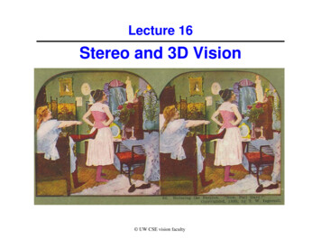
Lecture 16Stereo and 3D Vision UW CSE vision faculty
Stereoscopes: A 19th Century Pastime
Public Library, Stereoscopic Looking Room, Chicago, by Phillips, 1923
Teesta suspension bridge-Darjeeling, India
Woman getting eye exam during immigration procedure at EllisIsland, c. 1905 - 1920 , UCR Museum of Phography
Mark Twain at Pool Table", no date, UCR Museum of Photography
AnaglyphsAnaglyphs provide a stereoscopic 3D effect whenviewed with 2-color glasses (each lens achromatically opposite color, usually red and cyan).http://en.wikipedia.org/wiki/Anaglyph imageA free pair of red-blue stereo glasses can be ordered from Rainbow Symphony Inc http://www.rainbowsymphony.com/freestuff.html
3D Movies
How do we get 3D from Stereo Images?Perception of depth arises from “disparity” of a given 3D point inyour right and left retinal images3D pointleft imageright imagedisparity: the difference in image location of the same 3Dpoint when projected under perspective to two different camerasd xleft - xright
Recall (from Lecture 5): Perspective Projectionreal imagepoint EThis is the axis of thereal image plane.camera lensOfimage of pointB in front imageDxizxB3D objectpointO is the center of projection.This is the axis of the frontimage plane, which we use.xi xfz(from similar triangles)Z(Note: For convenience, we orient Z axis as above and use f instead of –f as in lecture 5)
Projection for Stereo ImagesSimple Model: Optic axes of 2 cameras are parallelimage planeszfcamera LZxlbbaselinecamera Rfxrx-bXzf xxlzfP (x,z)x-b xrzf(from similar triangles) y ylyyrY-axis isperpendicularto the page.
3D from Stereo Images: TriangulationFor stereo cameras with parallel optical axes, focal length f,baseline b, corresponding image points (xl,yl) and (xr,yr), thelocation of the 3D point can be derived from previous slide’sequations:Depth z f*b / (xl - xr) f*b/dx xl*z/f or b xr*z/fy yl*z/f or yr*z/fThis method ofdetermining depthfrom disparity d iscalled triangulation.Note that depth is inversely proportional to disparity
Depth z f*b / (xl - xr) f*b/dx xl*z/f or b xr*z/fy yl*z/f or yr*z/fTwo main problems:1. Need to know focal length f, baseline b- use prior knowledge or camera calibration2. Need to find corresponding point (xr,yr) foreach (xl,yl) Correspondence problem
Solving the stereo correspondence problem1. Cross correlation or SSD using small windows.dense2. Symbolic feature matching, usually using segments/corners.sparse3. Use the newer interest operators, e.g., SIFT.sparse
Given a point in the left image, do you needto search the entire right image for thecorresponding point?
Epipolar Constraint for CorrespondenceEpipolar plane plane connecting C1, C2, and point P Pz1y1z2y2P1C1bP2epipolarplanexC2.Epipolar plane cuts through image planes forming an epipolarline in each planeMatch for P1 (or P2) in the other image must lie on epipolar line
Epipolar Constraint for CorrespondenceMatch for P1 in the other image must lie on epipolar lineSo need search only along this linePP1C1bC2Epipolar line
What if the optical axes of the 2cameras are not parallel to each other?
Epipolar constraint still holds Pe1 and e2 are the epipolarlines for point Py1y2P1e2e1P2x2x1C1C2But the epipolar lines may no longer be horizontalJava demo: http://www.ai.sri.com/ luong/research/Meta3DViewer/EpipolarGeo.html
ExampleYellow epipolarlines for the threepoints shown onthe left image(from a slide by Pascal Fua)Given a point P1 in left image on epipolar line e1, can findepipolar line e2 provided we know relative orientations ofcameras Requires camera calibration (see lecture 5)
Alternate approach: Stereo image rectification ¾Reproject image planes onto a commonplane parallel to the line between optical centersEpipolar line is horizontal after this transformationTwo homographies (3x3 transforms), one for eachinput image reprojection, is computed. See:C. Loop and Z. Zhang. Computing Rectifying Homographies forStereo Vision. IEEE Conf. Computer Vision and Pattern Recognition,1999.
ExampleAfter rectification, need only search for matches alonghorizontal scan line(adapted from slide by Pascal Fua)
Your basic stereo algorithmFor each epipolar lineFor each pixel in the left image compare with every pixel on same epipolar line in right image pick pixel with minimum match costImprovement: match windowsA good survey and evaluation: http://vision.middlebury.edu/stereo/
Matching using Sum of Squared Differences (SSD)
Stereo matching based on SSDSSDdminBest matching disparityd
Problems with window sizeInput stereo pairW 3Effect of window size W Smaller window Good precision, more detail– Sensitive to noise Larger window Robust to noise– Reduced precision, less detailW 20
Example depth from stereo results Data from University of TsukubaSceneGround truth
Results with window-based stereo matchingWindow-based matching(best window size)Ground truth
Better methods exist.State of the art method:Ground truthBoykov et al., Fast Approximate Energy Minimization via Graph Cuts,International Conference on Computer Vision, 1999For the latest and greatest: http://www.middlebury.edu/stereo/
State of the art: Stereo as energy minimizationWhat defines a good stereo correspondence?1. Match quality–Want each pixel to find a good match in the other image2. Smoothness–If two pixels are adjacent, they should (usually) be displacedabout the same amount i.e., have similar disparities
Stereo as energy minimizationExpressing this mathematically1. Match quality–Want each pixel to find a good match in the other image2. Smoothness–If two pixels are adjacent, they should has similar disparitiesWe want to minimize
Stereo as energy minimizationWe want to minimize: Image as a graph withdisparity labelsThis is a special type of energyfunction known as an MRF(Markov Random Field)–Effective and fast algorithmshave been recently developed:» Graph cuts, beliefpropagation .» for more details (and code):http://vision.middlebury.edu/MRF/Min-cost graph cutyields a labeling ofeach pixel with bestdisparity
Stereo reconstruction pipelineSteps Calibrate camerasRectify imagesCompute disparityEstimate depthWhat will cause errors? Camera calibration errorsPoor image resolutionOcclusionsViolations of brightness constancy (specular reflections)Large motionsLow-contrast image regions
Example Application: Robot NavigationNomad robot searches for meteorites in obot/index.htmlStereo also used in Mars Rover (Clark Olson’s guest lecture)
Anaglyph from Mars Rover
What if 3D object has little or no texture?Matching points might be difficult or impossibleCan we still recover depth information?
Idea: Use structured light!Disparity between laser points on the same scanline in the imagesdetermines the 3-D coordinates of the laser point on objecthttp://www.cs.wright.edu/ agoshtas/stereorange.html
Recovered 3D Modelhttp://www.cs.wright.edu/ agoshtas/stereorange.html
Actually, we can make do with just 1 cameraVirtual “image” planeintersecting laser beam atsame distance as camera’simage placeAngle θbFrom calibration of both camera and light projector, we cancompute 3D coordinates laser points on the surface
The Digital Michelangelo ProjectObjectDirection of travelLaser sheetCCD image planeCylindrical mich/Optical triangulation Project a single stripe of laser light Scan it across the surface of the object
Laser scanned modelsThe Digital Michelangelo Project, Levoy et al.
Laser scanned modelsThe Digital Michelangelo Project, Levoy et al.
Laser scanned modelsThe Digital Michelangelo Project, Levoy et al.
Laser scanned modelsThe Digital Michelangelo Project, Levoy et al.
Laser scanned modelsThe Digital Michelangelo Project, Levoy et al.
A cool stereo application: Video View arryz/videoviewinterpolation.htm
Now, for Project 2 voting results
3rd Place Winners (3-way tie)Alex Eckerman and Mike Chung (52 votes)John Lyon and James George (52 votes)Aron Ritchie and Andrew Reusch (52 votes)
2nd Place WinnerParamjit Singh Sandhu and Zhen Wang (63 votes)
Drumroll please
1st Place WinnerBrice Johnson and Will Johnson (68 votes)
Next Time: Guest lecture by Richard LadnerThings to do: Work on Project 4
left image right image 3D point disparity: . Match for P1 in the other image must lie on epipolar line . Two homographies (3x3 transforms), one for each input image reprojection, is computed. See: ¾C. Loop and Z. Zhang. Computing Rectifying Homographies for Stereo Vision. IEEE Conf. Computer Vision and Pattern Recognition,