Transcription
Cortex -M4 Devices Generic User GuideCopyright 2010 ARM. All rights reserved.ARM DUI 0553A (ID121610)
Cortex-M4 DevicesGeneric User GuideCopyright 2010 ARM. All rights reserved.Release InformationThe following changes have been made to this book.Change historyDateIssueConfidentialityChange16 December 2010ANon-ConfidentialFirst releaseProprietary NoticeWords and logos marked with or are registered trademarks or trademarks of ARM in the EU and other countries,except as otherwise stated below in this proprietary notice. Other brands and names mentioned herein may be thetrademarks of their respective owners.Neither the whole nor any part of the information contained in, or the product described in, this document may beadapted or reproduced in any material form except with the prior written permission of the copyright holder.The product described in this document is subject to continuous developments and improvements. All particulars of theproduct and its use contained in this document are given by ARM in good faith. However, all warranties implied orexpressed, including but not limited to implied warranties of merchantability, or fitness for purpose, are excluded.This document is intended only to assist the reader in the use of the product. ARM shall not be liable for any loss ordamage arising from the use of any information in this document, or any error or omission in such information, or anyincorrect use of the product.Where the term ARM is used it means “ARM or any of its subsidiaries as appropriate”.Confidentiality StatusThis document is Non-Confidential. The right to use, copy and disclose this document may be subject to licenserestrictions in accordance with the terms of the agreement entered into by ARM and the party that ARM delivered thisdocument to.Product StatusThe information in this document is final, that is for a developed product.Web Addresshttp://www.arm.comARM DUI 0553AID121610Copyright 2010 ARM. All rights reserved.Non-Confidentialii
ContentsCortex-M4 Devices Generic User GuidePrefaceAbout this book . viFeedback . ixChapter 1Introduction1.1Chapter 2About the Cortex-M4 processor and core peripherals . 1-2The Cortex-M4 Processor2.12.22.32.42.5Chapter 3Programmers model . 2-2Memory model . 2-12Exception model . 2-21Fault handling . 2-29Power management . 2-32The Cortex-M4 Instruction Set3.13.23.33.43.53.63.73.83.93.103.113.12ARM DUI 0553AID121610Instruction set summary . 3-2CMSIS functions . 3-9About the instruction descriptions . 3-11Memory access instructions . 3-22General data processing instructions . 3-39Multiply and divide instructions . 3-74Saturating instructions . 3-95Packing and unpacking instructions . 3-107Bitfield instructions . 3-114Branch and control instructions . 3-118Floating-point instructions . 3-126Miscellaneous instructions . 3-157Copyright 2010 ARM. All rights reserved.Non-Confidentialiii
Chapter 4Cortex-M4 Peripherals4.14.24.34.44.54.6Appendix AAbout the Cortex-M4 peripherals . 4-2Nested Vectored Interrupt Controller . 4-3System control block . 4-11System timer, SysTick . 4-33Optional Memory Protection Unit . 4-37Floating Point Unit (FPU) . 4-48Cortex-M4 OptionsA.1Cortex-M4 implementation options . A-2GlossaryARM DUI 0553AID121610Copyright 2010 ARM. All rights reserved.Non-Confidentialiv
PrefaceThis preface introduces the Cortex-M4 Devices Generic User Guide. It contains the followingsections: About this book on page vi Feedback on page ix.ARM DUI 0553AID121610Copyright 2010 ARM. All rights reserved.Non-Confidentialv
PrefaceAbout this bookThis book is a generic user guide for devices that implement the ARM Cortex-M4 processor.Implementers of Cortex-M4 designs make a number of implementation choices, that can affectthe functionality of the device. This means that, in this book: some information is described as implementation-defined some features are described as optional.In this book, unless the context indicates otherwise:ProcessorRefers to the Cortex-M4 processor, as supplied by ARM.DeviceRefers to an implemented device, supplied by an ARM partner, that incorporatesa Cortex-M4 processor. In particular, your device refers to the particularimplementation of the Cortex-M4 that you are using. Some features of yourdevice depend on the implementation choices made by the ARM partner thatmade the device.Product revision statusThe rnpn identifier indicates the revision status of the product described in this book, where:rnIdentifies the major revision of the product.pnIdentifies the minor revision or modification status of the product.Intended audienceThis book is written for application and system-level software developers, familiar withprogramming, who want to program a device that includes the Cortex-M4 processor.Using this bookThis book is organized into the following chapters:Chapter 1 IntroductionRead this for an introduction to the Cortex-M4 processor and its features.Chapter 2 The Cortex-M4 ProcessorRead this for information about how to program the processor, the processormemory model, exception and fault handling, and power management.Chapter 3 The Cortex-M4 Instruction SetRead this for information about the processor instruction set.Chapter 4 Cortex-M4 PeripheralsRead this for information about Cortex-M4 peripherals.Appendix A Cortex-M4 OptionsRead this for information about the processor implementation and configurationoptions.GlossaryARM DUI 0553AID121610Read this for definitions of terms used in this book.Copyright 2010 ARM. All rights reserved.Non-Confidentialvi
PrefaceTypographical conventionsThe typographical conventions used in this document are:italicHighlights important notes, introduces special terminology, denotesinternal cross-references, and citations.boldUsed for terms in descriptive lists, where appropriate.monospaceDenotes text that you can enter at the keyboard, such as commands, fileand program names, and source code.monospace italicDenotes arguments to monospace text where the argument is to bereplaced by a specific value. and Enclose replaceable terms for assembler syntax where they appear in codeor code fragments. For example:CMP Rn, Rm #imm ARM DUI 0553AID121610Copyright 2010 ARM. All rights reserved.Non-Confidentialvii
PrefaceAdditional readingThis section lists publications by ARM and by third parties.See Infocenter, http://infocenter.arm.com, for access to ARM documentation.See onARM, http://onarm.com, for embedded software development resources including theCortex Microcontroller Software Interface Standard (CMSIS).ARM publicationsThis book contains information that is specific to this product. See the following documents forother relevant information: Cortex-M4 Technical Reference Manual (ARM DDI 0439) ARMv7-M Architecture Reference Manual (ARM DDI 0403).Other publicationsThis guide only provides generic information for devices that implement the ARM Cortex-M4processor. For information about your device see the documentation published by the devicemanufacturer.ARM DUI 0553AID121610Copyright 2010 ARM. All rights reserved.Non-Confidentialviii
PrefaceFeedbackARM welcomes feedback on this product and its documentation.Feedback on contentIf you have comments on content then send an e-mail to errata@arm.com. Give: the title the number, ARM DUI 0553A the page numbers to which your comments apply a concise explanation of your comments.ARM also welcomes general suggestions for additions and improvements.ARM DUI 0553AID121610Copyright 2010 ARM. All rights reserved.Non-Confidentialix
Chapter 1IntroductionThis chapter introduces the Cortex-M4 processor and its features. It contains the following section: ARM DUI 0553AID121610About the Cortex-M4 processor and core peripherals on page 1-2.Copyright 2010 ARM. All rights reserved.Non-Confidential1-1
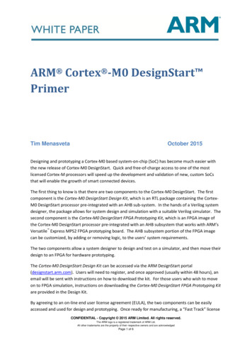
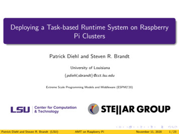
Introduction1.1About the Cortex-M4 processor and core peripheralsThe Cortex-M4 processor is a high performance 32-bit processor designed for themicrocontroller market. It offers significant benefits to developers, including: outstanding processing performance combined with fast interrupt handling enhanced system debug with extensive breakpoint and trace capabilities efficient processor core, system and memories ultra-low power consumption with integrated sleep mode and an optional deep sleepmode platform security robustness, with optional integrated Memory Protection Unit (MPU).Cortex-M4processorOptionalWICOptional FPUNVICOptionalDebugAccess PortOptionalEmbeddedTrace MacrocellProcessorcoreOptionalSerial WireviewerOptional Memoryprotection unitOptionalFlashpatchOptionalDatawatchpointsBus matrixCodeinterfaceSRAM andperipheral interfaceFigure 1-1 Cortex-M4 implementationThe Cortex-M4 processor is built on a high-performance processor core, with a 3-stage pipelineHarvard architecture, making it ideal for demanding embedded applications. The processordelivers exceptional power efficiency through an efficient instruction set and extensivelyoptimized design, providing high-end processing hardware including optionalIEEE754-compliant single-precision floating-point computation, a range of single-cycle andSIMD multiplication and multiply-with-accumulate capabilities, saturating arithmetic anddedicated hardware division.To facilitate the design of cost-sensitive devices, the Cortex-M4 processor implementstightly-coupled system components that reduce processor area while significantly improvinginterrupt handling and system debug capabilities. The Cortex-M4 processor implements aversion of the Thumb instruction set based on Thumb-2 technology, ensuring high code densityand reduced program memory requirements. The Cortex-M4 instruction set provides theexceptional performance expected of a modern 32-bit architecture, with the high code densityof 8-bit and 16-bit microcontrollers.The Cortex-M4 processor closely integrates a configurable Nested Vectored InterruptController (NVIC), to deliver industry-leading interrupt performance. The NVIC includes aNon Maskable Interrupt (NMI) that can provide up to 256 interrupt priority levels. The tightintegration of the processor core and NVIC provides fast execution of Interrupt ServiceARM DUI 0553AID121610Copyright 2010 ARM. All rights reserved.Non-Confidential1-2
IntroductionRoutines (ISRs), dramatically reducing the interrupt latency. This is achieved through thehardware stacking of registers, and the ability to suspend load-multiple and store-multipleoperations. Interrupt handlers do not require wrapping in assembler code, removing any codeoverhead from the ISRs. A tail-chain optimization also significantly reduces the overhead whenswitching from one ISR to another.To optimize low-power designs, the NVIC integrates with the sleep modes, that includes anoptional deep sleep function. This enables the entire device to be rapidly powered down whilestill retaining program state.1.1.1System-level interfaceThe Cortex-M4 processor provides multiple interfaces using AMBA technology to providehigh speed, low latency memory accesses. It supports unaligned data accesses and implementsatomic bit manipulation that enables faster peripheral controls, system spinlocks and thread-safeBoolean data handling.The Cortex-M4 processor has an optional Memory Protection Unit (MPU) that permits controlof individual regions in memory, enabling applications to utilize multiple privilege levels,separating and protecting code, data and stack on a task-by-task basis. Such requirements arebecoming critical in many embedded applications such as automotive.1.1.2Optional integrated configurable debugThe Cortex-M4 processor can implement a complete hardware debug solution. This provideshigh system visibility of the processor and memory through either a traditional JTAG port or a2-pin Serial Wire Debug (SWD) port that is ideal for microcontrollers and other small packagedevices.For system trace the processor integrates an Instrumentation Trace Macrocell (ITM) alongsidedata watchpoints and a profiling unit. To enable simple and cost-effective profiling of the systemevents these generate, a Serial Wire Viewer (SWV) can export a stream of software-generatedmessages, data trace, and profiling information through a single pin.The optional Embedded Trace Macrocell (ETM) delivers unrivalled instruction trace capturein an area far smaller than traditional trace units, enabling many low cost MCUs to implementfull instruction trace for the first time.The optional Flash Patch and Breakpoint Unit (FPB) provides up to eight hardware breakpointcomparators that debuggers can use. The comparators in the FPB also provide remap functionsof up to eight words in the program code in the CODE memory region. This enables applicationsstored on a non-erasable, ROM-based microcontroller to be patched if a small programmablememory, for example flash, is available in the device. During initialization, the application inROM detects, from the programmable memory, whether a patch is required. If a patch isrequired, the application programs the FPB to remap a number of addresses. When thoseaddresses are accessed, the accesses are redirected to a remap table specified in the FPBconfiguration, which means the program in the non-modifiable ROM can be patched.1.1.3Cortex-M4 processor features and benefits summary tight integration of system peripherals reduces area and development costs Thumb instruction set combines high code density with 32-bit performance optional IEEE754-compliant single-precision FPU code-patch ability for ROM system updates power control optimization of system components integrated sleep modes for low power consumptionARM DUI 0553AID121610Copyright 2010 ARM. All rights reserved.Non-Confidential1-3
Introduction 1.1.4fast code execution permits slower processor clock or increases sleep mode timehardware division and fast digital-signal-processing orientated multiply accumulatesaturating arithmetic for signal processingdeterministic, high-performance interrupt handling for time-critical applicationsoptional Memory Protection Unit (MPU) for safety-critical applicationsextensive implementation-defined debug and trace capabilities:— Serial Wire Debug and Serial Wire Trace reduce the number of pins required fordebugging, tracing, and code profiling.Cortex-M4 core peripheralsThese are:Nested Vectored Interrupt ControllerThe NVIC is an embedded interrupt controller that supports low latency interruptprocessing.System Control BlockThe System Control Block (SCB) is the programmers model interface to theprocessor. It provides system implementation information and system control,including configuration, control, and reporting of system exceptions.System timerThe system timer, SysTick, is a 24-bit count-down timer. Use this as a Real TimeOperating System (RTOS) tick timer or as a simple counter.Memory Protection UnitThe Memory Protection Unit (MPU) improves system reliability by defining thememory attributes for different memory regions. It provides up to eight differentregions, and an optional predefined background region.Floating-point UnitThe Floating-Point Unit (FPU) provides IEEE754-compliant operations onsingle-precision, 32-bit, floating-point values.ARM DUI 0553AID121610Copyright 2010 ARM. All rights reserved.Non-Confidential1-4
Chapter 2The Cortex-M4 ProcessorThis chapter describes the Cortex-M4 processor. It contains the following sections: Programmers model on page 2-2 Memory model on page 2-12 Exception model on page 2-21 Fault handling on page 2-29 Power management on page 2-32.ARM DUI 0553AID121610Copyright 2010 ARM. All rights reserved.Non-Confidential2-1
The Cortex-M4 Processor2.1Programmers modelThis section describes the Cortex-M4 programmers model. In addition to the individual coreregister descriptions, it contains information about the processor modes and privilege levels forsoftware execution and stacks.2.1.1Processor mode and privilege levels for software executionThe processor modes are:Thread modeUsed to execute application software. The processor enters Thread modewhen it comes out of reset.Handler modeUsed to handle exceptions. The processor returns to Thread mode when ithas finished all exception processing.The privilege levels for software execution are:UnprivilegedThe software: has limited access to the MSR and MRS instructions, and cannot use theCPS instruction cannot access the system timer, NVIC, or system control block might have restricted access to memory or peripherals.Unprivileged software executes at the unprivileged level.PrivilegedThe software can use all the instructions and has access to all resources.Privileged software executes at the privileged level.In Thread mode, the CONTROL register controls whether software execution is privileged orunprivileged, see CONTROL register on page 2-9. In Handler mode, software execution isalways privileged.Only privileged software can write to the CONTROL register to change the privilege level forsoftware execution in Thread mode. Unprivileged software can use the SVC instruction to makea supervisor call to transfer control to privileged software.2.1.2StacksThe processor uses a full descending stack. This means the stack pointer holds the address ofthe last stacked item in memory. When the processor pushes a new item onto the stack, itdecrements the stack pointer and then writes the item to the new memory location. Theprocessor implements two stacks, the main stack and the process stack, with a pointer for eachheld in independent registers, see Stack Pointer on page 2-4.In Thread mode, the CONTROL register controls whether the processor uses the main stack orthe process stack, see CONTROL register on page 2-9. In Handler mode, the processor alwaysuses the main stack. The options for processor operations are:Table 2-1 Summary of processor mode, execution privilege level, and stack use optionsProcessormodeUsed to executePrivilege level forsoftware executionStack usedThreadApplicationsPrivileged or unprivileged aMain stack or process stack aHandlerException handlersAlways privilegedMain stacka. See CONTROL register on page 2-9.ARM DUI 0553AID121610Copyright 2010 ARM. All rights reserved.Non-Confidential2-2
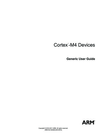
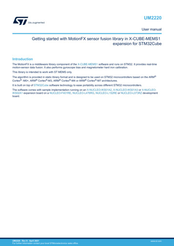
The Cortex-M4 Processor2.1.3Core registersThe processor core registers are:R0R1R2Low registersR3R4R5General-purpose registersR6R7R8R9High registersR10R11R12Stack PointerSP (R13)Link RegisterLR (R14)Program CounterPC (R15)PSRPSP‡MSP‡‡Banked version of SPProgram status registerPRIMASKFAULTMASKException mask registersSpecial registersBASEPRICONTROLCONTROL registerTable 2-2 Core register set summaryNameType aRequired privilege bReset se registers on page 2-4MSPRWPrivilegedSee descriptionStack Pointer on page 2-4PSPRWEitherUnknownStack Pointer on page 2-4LRRWEither0xFFFFFFFFLink Register on page 2-4PCRWEitherSee descriptionProgram Counter on page 2-4PSRRWPrivileged0x01000000Program Status Register on page 2-4ASPRRWEitherUnknownApplication Program Status Register on page 2-5IPSRROPrivileged0x00000000Interrupt Program Status Register on page 2-6EPSRROPrivileged0x01000000Execution Program Status Register on page 2-6PRIMASKRWPrivileged0x00000000Priority Mask Register on page 2-8FAULTMASKRWPrivileged0x00000000Fault Mask Register on page 2-8BASEPRIRWPrivileged0x00000000Base Priority Mask Register on page 2-9CONTROLRWPrivileged0x00000000CONTROL register on page 2-9a. Describes access type during program execution in thread mode and Handler mode. Debug access can differ.b. An entry of Either means privileged and unprivileged software can access the register.ARM DUI 0553AID121610Copyright 2010 ARM. All rights reserved.Non-Confidential2-3
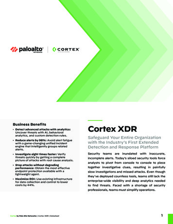
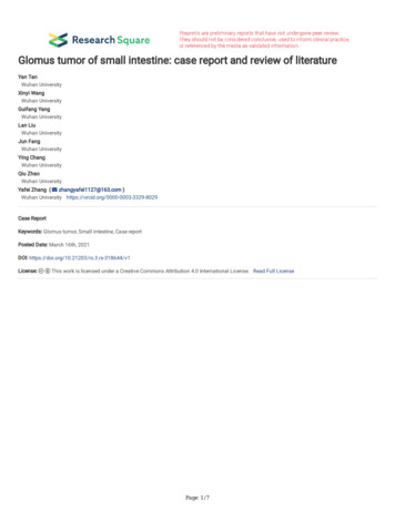
The Cortex-M4 ProcessorGeneral-purpose registersR0-R12 are 32-bit general-purpose registers for data operations.Stack PointerThe Stack Pointer (SP) is register R13. In Thread mode, bit[1] of the CONTROL registerindicates the stack pointer to use: 0 Main Stack Pointer (MSP). This is the reset value. 1 Process Stack Pointer (PSP).On reset, the processor loads the MSP with the value from address 0x00000000.Link RegisterThe Link Register (LR) is register R14. It stores the return information for subroutines, functioncalls, and exceptions. On reset, the processor sets the LR value to 0xFFFFFFFF.Program CounterThe Program Counter (PC) is register R15. It contains the current program address. On reset,the processor loads the PC with the value of the reset vector, which is at address 0x00000004.Bit[0] of the value is loaded into the EPSR T-bit at reset and must be 1.Program Status RegisterThe Program Status Register (PSR) combines: Application Program Status Register (APSR) Interrupt Program Status Register (IPSR) Execution Program Status Register (EPSR).These registers are mutually exclusive bitfields in the 32-bit PSR. The bit assignments are:31 30 29 28 27 26 25 24 2316 15APSR N Z C V QReservedReserved0ReservedIPSREPSR10 9 8ICI/IT TReservedISR NUMBERICI/ITReservedAccess these registers individually or as a combination of any two or all three registers, usingthe register name as an argument to the MSR or MRS instructions. For example: read all of the registers using PSR with the MRS instruction write to the APSR N, Z, C, V, and Q bits using APSR nzcvq with the MSR instruction.ARM DUI 0553AID121610Copyright 2010 ARM. All rights reserved.Non-Confidential2-4
The Cortex-M4 ProcessorThe PSR combinations and attributes are:Table 2-3 PSR register combinationsRegisterTypeCombinationPSRRWa, bAPSR, EPSR, and IPSRIEPSRROEPSR and IPSRIAPSRRWaAPSR and IPSREAPSRRWbAPSR and EPSRa. The processor ignores writes to the IPSRbits.b. Reads of the EPSR bits return zero, and theprocessor ignores writes to the these bitsSee the instruction descriptions MRS on page 3-163 and MSR on page 3-164 for moreinformation about how to access the program status registers.Application Program Status RegisterThe APSR contains the current state of the condition flags from previous instruction executions.See the register summary in Table 2-2 on page 2-3 for its attributes. The bit assignments are:Table 2-4 APSR bit assignmentsARM DUI 0553AID121610BitsNameFunction[31]NNegative flag[30]ZZero flag[29]CCarry or borrow flag[28]VOverflow flag[27]QDSP overflow and saturation flag[26:20]-Reserved[19:16]GE[3:0]Greater than or Equal flags. See SEL onpage 3-70 for more information.[15:0]-ReservedCopyright 2010 ARM. All rights reserved.Non-Confidential2-5
The Cortex-M4 ProcessorInterrupt Program Status RegisterThe IPSR contains the exception type number of the current Interrupt Service Routine (ISR).See the register summary in Table 2-2 on page 2-3 for its attributes. The bit assignments are:Table 2-5 IPSR bit assignmentsBitsNameFunction[31:9]-Reserved[8:0]ISR NUMBERThis is the number of the current exception:0 Thread mode1 Reserved2 NMI3 HardFault4 MemManage5 BusFault6 UsageFault7-10 Reserved11 SVCall12 Reserved for Debug13 Reserved14 PendSV15 SysTick16 IRQ0.n 15 IRQ(n-1)asee Exception types on page 2-21 for more information.a. The number of interrupts, n, is implementation-defined, in the range 1-240.Execution Program Status RegisterThe EPSR contains the Thumb state bit, and the execution state bits for either the: If-Then (IT) instruction Interruptible-Continuable Instruction (ICI) field for an interrupted load multiple or storemultiple instruction.See the register summary in Table 2-2 on page 2-3 for the EPSR attributes. The bit assignmentsare:Table 2-6 EPSR bit assignmentsARM DUI 25], [15:10]ICIInterruptible-continuable instruction bits, see Interruptible-continuable instructionson page 2-7.[26:25], [15:10]ITIndicates the execution state bits of the IT instruction, see IT on page 3-122.Copyright 2010 ARM. All rights reserved.Non-Confidential2-6
The Cortex-M4 ProcessorTable 2-6 EPSR bit assignments (continued)BitsNameFunction[24]TThumb state bit, see Thumb state.[23:16]-Reserved.[9:0]-Reserved.Attempts to read the EPSR directly through application software using the MSR instructionalways return zero. Attempts to write the EPSR using the MSR instruction in application softwareare ignored.Interruptible-continuable instructionsWhen an interrupt occurs during the execution of an LDM, STM, PUSH, or POP instruction, and whenan FPU is implemented an VLDM, VSTM, VPUSH, or VPOP instruction, the processor: stops the load multiple or store multiple instruction operation temporarily stores the next register operand in the multiple operation to EPSR bits[15:12].After servicing the interrupt, the processor: returns to the register pointed to by bits[15:12] resumes execution of the multiple load or store instruction.When the EPSR holds ICI execution state, bits[26:25,11:10] are zero.If-Then blockThe If-Then block contains up to four instructions following an IT instruction. Each instructionin the block is conditional. The conditions for the instructions are either all the same, or somecan be the inverse of others. See IT on page 3-122 for more information.Thumb stateThe Cortex-M4 processor only supports execution of instructions in Thumb state. The followingcan clear the T bit to 0: instructions BLX, BX and POP{PC} restoration from the stacked xPSR value on an exception return bit[0] of the vector value on an exception entry or reset.Attempting to execute instructions when the T bit is 0 results in a fault or lockup. See Lockupon page 2-31 for more information.Exception mask registersThe exception mask registers disable the handling of exceptions by the processor. Disableexceptions where they might impact on timing critical tasks.To access the exception mask registers use the MSR and MRS instructions, or the CPS instruction tochange the value of PRIMASK or FAULTMASK. See MRS on page 3-163, MSR on page 3-164,and CPS on page 3-159 for more information.ARM DUI 0553AID121610Copyright 2010 ARM. All rights reserved.Non-Confidential2-7
The Cortex-M4 ProcessorPriority Mask RegisterThe PRIMASK register prevents activation of all exceptions with configurable priority. See theregister summary in Table 2-2 on page 2-3 for its attributes. The bit assignments are:1 031ReservedPRIMASKTable 2-7 PRIMASK register bit SK0 no effect1 prevents the activation of all exceptions with configurable priority.Fault Mask RegisterThe FAULTMASK register prevents activation of all exceptions except for Non-MaskableInterrupt (NMI). See the register summary in Table 2-2 on page 2-3 for its attributes. The bitassignments are:311 0ReservedFAULTMASKTable 2-8 FAULTMASK register bit MASK0 no effect1 prevents the activation of all exceptions except for NMI.The processor clears the FAULTMASK bit to 0 on exit from any exception handler except theNMI handler.ARM DUI 0553AID121610Copyright 2010 ARM. All rights reserved.Non-Confidential2-8
The Cortex-M4 ProcessorBase Priority Mask RegisterThe BASEPRI register defines the minimum priority for exception processing. When BASEPRIis set to a nonzero value, it prevents the activation of all exceptions with the same or lowerpriority level as the BASEPRI value. See the register summary in Table 2-2 on page 2-3 for itsattributes. The bit assignments are:318 7Reserved0BASEPRITable 2-9 BASEPRI register bit EPRI aPriority mask bits:0x00 no effectNonzero defines the base priority for exception processing.The processor does not process any exception with a priority value greater than or equal to BASEPRI.a. This field is similar
Cortex-M4 Technical Reference Manual . The Cortex-M4 processor has an optional Memory Protection Unit (MPU) that permits control of individual regions in memory, enabling applications to utilize multiple privilege levels, separating and protecting code, data and stack on a task-by-task basis. Such requirements are