Transcription
CHANGES IN SEISMIC DESIGN CRITERIA AND DESIGN GROUND MOTIONS IN IBC 2018 AND ASCE 7-16,AND RECOMMENDATIONS FOR SEISMIC DESIGN PRACTICE IN UTAHPrepared by: Travis Gerber, PhD, PE; Jerod Johnson, PhD, SE;Brent Maxfield, SE; Kevin Franke, PhD, PE; and Ryan Maw, PEEndorsed by: Utah Geo-Institute Chapter of the American Society of Civil Engineers (ASCE),Utah Section of ASCE, Structural Engineers Association of Utah (SEAU),Utah Chapter of the Earthquake Engineering Research Institute (EERI), andUtah Chapter of the Structural Engineering Institute (SEI).January 31, 2020ABSTRACTThe 2018 International Building Code (IBC 2018), and by extension referenced provisions of ASCE 7-16,was adopted July 2019 by the State of Utah. ASCE 7-16 introduces significant changes to prescribedseismic forces for the design of structures when compared to IBC 2015 and ASCE 7-10. These changesinclude updated mapped B/C boundary seismic values Ss and S1 as well as revised site coefficients (withthe coefficients typically being larger). Most notable are new requirements to perform site-specificground motion hazard analyses (GMHA, which is comprised of both deterministic seismic hazardanalysis [DSHA] and probabilistic seismic hazard analysis [PSHA]) for areas of moderate to highseismicity and softer soil sites (Site Classes D and E). This site-specific study requirement is the result ofdeficiencies which are now more widely recognized in the shape and magnitude of the code-based(“standard”) design response spectrum. In some cases, exceptions exist where an otherwise requiredGMHA may be omitted; however, these exceptions together with the other changes in ASCE 7-16 canincrease design base shears by as much as 70%. In early 2019, a group of individuals from severalprofessional societies formed an ad-hoc committee to develop a workshop whose purpose was to helpinform fellow engineering and geological professionals in Utah about these changes. In preparing forthe workshop, various design practice issues not explicitly addressed in IBC 2018 or ASCE 7-16 werediscussed. The outcome of these discussions were consensus recommendations which are believed bycommittee members to represent good seismic design practices. This document presents several ofthose recommendations, including minimum qualifications for those performing site-specific seismicstudies as well as the typical content of such reports.INTRODUCTION AND BACKGROUNDWith the recent adoption of IBC 2018 (and by extension the seismic design standards of ASCE 7-16) bythe State of Utah, individuals experienced in seismic design procedures came together in an effort tohelp inform fellow engineering and geological professionals regarding changes in practice that thisadoption entails. These individuals reached out to professional organizations and other pertinentparties to form an ad-hoc committee representing a wide spectrum of earthquake engineering designpractitioners and affiliated parties to put on a workshop about the updated seismic ground motionprovisions of these two code documents as well as to help create this follow-on document.Page 1 of 18
The workshop was held on June 10, 2019, in Sandy, Utah and consisted of three presentations and apanel-led discussion. The workshop was attended by over 150 individuals and received support fromthe following organizations: Utah Geo-Institute Chapter of the American Society of Civil Engineers(ASCE), Structural Engineers Association of Utah (SEAU), Utah Section of ASCE, Utah Chapter of theEarthquake Engineering Research Institute (EERI), Utah Chapter of the Structural Engineering Institute(SEI), Utah Geological Survey (UGS), and Utah Division of Facilities Construction Management (DFCM).The intent of this document is to highlight changes in seismic design practices (relative to previous codedocuments IBC 2015 and ASCE 7-10) through items such as revised site coefficients and requirementsfor site-specific seismic studies. This document also presents the consensus thoughts of the ad-hoccommittee and workshop panel members regarding certain issues not explicitly addressed by the codedocuments and, in the opinion of the group, represent good practices. These recommendations arepresented in the second half of this document.CODE CHANGESEngineers regularly using the ASCE 7 standard have come to understand that changes in prescribedearthquake forces are to be expected within each cycle of this standard. Most common are subtledifferences that do not result in significant changes to prescribed lateral forces or procedures used forthe design of buildings and other structures. The 2016 Edition of the ASCE 7 standard is clearly anexception to this.Changes in Mapped Spectral Acceleration Values in UtahIn the western US, provisions of ASCE 7-10 utilized spectral acceleration values developed from the NextGeneration Attenuation (NGA) West effort. This multidisciplinary research program was coordinated bythe Lifelines Program of the Pacific Earthquake Engineering Research Center and was concluded in 2008,culminating in the development of the 2008 United States Geological Survey (USGS) Seismic HazardMaps. It was based upon sets of ground-motion attenuation models developed by independent, butinteracting, teams. The NGA West 2 effort initiated in 2008 was a follow-up program to the original NGAWest effort. The effort focused on developing a ground motion database that considers significantlymore earthquakes, verification of the original NGA West models for recent events, scaling of groundmotions via ground motion prediction equations (GMPEs) for different levels of damping, verticaleffects, soil non-linearity/amplification and uncertainty. The new seismic parameters prescribed byASCE 7-16 are the result of the NGA West 2 effort (which are included in the 2014 USGS Seismic HazardMaps). Future code iterations will undoubtedly adopt even more of the findings of NGA West 2 as wellas other future seismic research efforts.While some provisions for prescribed earthquake forces changed significantly, mapped spectralacceleration values in Utah show changes for the ASCE 7-16 not unlike those witnessed for the lastseveral code cycles. Tables 1 and 2 illustrate the differences in mapped spectral acceleration values forseveral Utah locations.Page 2 of 18
Table 1 – Generalized Short Period (Ss) Spectral Acceleration Values for Utah SitesSiteMurrayLoganBrigham CityOgdenProvoMantiCedar CitySt. GeorgeVernalMonticelloASCE .156ASCE ble 2 – Generalized Long Period (S1) Spectral Acceleration Values for Utah SitesSiteMurrayLoganBrigham CityOgdenProvoMantiCedar CitySt. GeorgeVernalMonticelloASCE .054ASCE Changes in mapped spectral acceleration values for both long and short periods (Ss, S1) are generallyminor with noteworthy increases for short period and long period accelerations in the Provo andSouthern Utah Areas. These accelerations are derived from the 2014 USGS National Seismic HazardMaps, where preceding codes referenced the maps from 2008.Changes in Site Coefficients and Quantification of Site Soil EffectsWhile design professionals should develop a general awareness of the changes in mapped spectralacceleration values, an understanding of the revised spectral response acceleration parameters (sitecoefficients) is essential. Prescriptive site coefficients (Fa and Fv) are intended to modify mappedspectral acceleration values for local site conditions and non-linear behavior. These values are based onsoil site class and, because soil behaves non-linearly, mapped acceleration levels.In common practice, seismic design forces are estimated using code-based seismic design parametersand/or the design response spectrum which are dependent on site coefficient values. In addition to thisapproach, there are two site-specific procedures that can more accurately determine spectral responsePage 3 of 18
than the response spectrum developed using site coefficients Fa and Fv and ASCE 7-16 Figure 11.4-1.Both of these procedures are described in ASCE 7-16 Chapter 21. The first procedure is a site responseanalysis (SRA; see Section 21.1). This analysis has been generally required for Site Class F soils forseveral ASCE 7 code cycles. This procedure uses a detailed soil model developed from site-specific data.Ground motions are transformed from a base layer (usually bedrock) through the soil profile to provideestimates of ground motions (and corresponding response spectrum) at the ground surface. A onedimensional SRA with vertically propagating shear waves is sometimes colloquially referred to as a“SHAKE” analysis, stemming from the name of the predominant computer code originally used toconduct such analyses. However, SHAKE is an equivalent linear analysis, and many times (particularlyfor liquefiable soils), a nonlinear analysis is needed. If performed correctly, an SRA is generallyconsidered a more accurate quantification of local site effects than reliance on simplified, code-basedsite coefficients. The base-rock response spectrum needed as input may be developed from ASCE 7’sprescriptive / code-based method or from a site-specific ground motion hazard analysis. It should benoted that actual site response during an earthquake is a three-dimensional problem which wecommonly try to quantify using one-dimensional site response tools. In many cases, one-dimensionalsite response analyses do not fully capture the true response, especially for structural periods largerthan the site period.The second procedure is a site-specific ground motion hazard analysis (GMHA; see Section 21.2). Thisprocedure is typically comprised of 1) a deterministic seismic hazard analysis [DSHA] and 2) probabilisticseismic hazard analysis [PSHA]. In the DSHA, the ground shaking hazard is assessed by identifyingspecific earthquake seismic events (“event scenarios”) – ones for which the combination of magnitudeand distance (together with other pertinent source and site parameters) provide relatively large levels ofground shaking. This process typically consists of checking multiple, active faults at an 84th percentile ofpotential values (hence reflecting the uncertainty in acceleration given any particular, fixed set of inputparameters) and using the peak acceleration response for each period to define the deterministicspectrum. In the PSHA, the ground shaking hazard is assessed in terms of statistical likelihood andreflects the combined effects of multiple potential seismic sources, including a background or griddedevent, each with its own recurrence relationship. The PSHA also accounts for uncertainties in the size(magnitude), location (distance), and rate of occurrence of each seismic source in the area of influence,as well as the variation of the ground motions themselves given a specific earthquake magnitude andlocation. For structural design, the probabilistic spectrum is assessed such that the ground motionsreflect the direction of maximum response as well as a level of shaking which would nominally result aone percent probability of structural collapse in 50 years. Both PSHA and DSHA consider such things asthe regional tectonic setting, geology, and historical seismicity; the characteristics of ground motionattenuation; near source effects; and the effects of subsurface site conditions. In ASCE 7-16, the lowerof the PSHA- and DSHA-based spectra is scaled to a design level and compared to certain specifiedminimums to obtain the site-specific design spectrum.The GMHA procedure can provide ground motion estimates at the surface in lieu of using standardizedsite coefficients. This procedure can also provide a target for spectral matching of ground motion inputswhich are transformed (deconvolved) to base rock as used in an SRA. A site-specific GMHA has beenPage 4 of 18
allowed in previous editions of ASCE 7, but in ASCE 7-16, it is now required, unless exceptions perSection 11.4.8 are taken, for the following:1. Seismically isolated structures and structures with damping systems on sites with S1 greaterthan or equal to 0.6.2. Structures on Site Class E sites with Ss greater than or equal to 1.0, and3. Structures on Site Class D and E sites with S1 greater than or equal to 0.2.There are three exceptions listed in Section 11.4.8 which can be invoked to avoid a GMHA, which will bedescribed later. It should be noted that ASCE 7-16 allows site-specific SRA or GMHA to be used for anystructure, but is now requiring GMHA for the three specific instances listed above. As discussed later,these instances typically represent situations where the otherwise-used, code-based design responsespectrum with its standardized shape may not adequately estimate expected spectral accelerations for aparticular site.In addition to the GMHA requirements, changes to the prescribed values for Fa are noteworthy withincreases of up to 20% for Site Classes C and D. The Fv coefficient for Site Class E can be as high as 4.2when developing a response spectrum in accordance with Chapter 11, which is again appreciably higherthan values in previous ASCE 7 code iterations. If the exceptions in Section 11.4.8 are taken, theincreases in design ground motions can be more than 50% from previous code iterations.ASCE 7-16 recognizes that robust site-specific analyses are not practical for a great many sites andprojects, which is why exceptions are provided that seek to alleviate the requirements of GMHA forsmaller projects where long period accelerations are not likely applicable. Designers may opt to use theexceptions for Site Classes D and E, but with increases in prescribed design forces for longer periods ashigh as 50%. Note that the exception is not allowed for Site Class E soils when the building period, T, isgreater than the value of Ts (which is equal to SD1/SDS: Use ASCE 7-16 Supplement 1 to get the value of Fvused to calculate the value of Ts).One of the most important parameters used to characterize local dynamic soil effects is the average soilshear wave velocity in the upper 30 meters (or 100 feet) of the soil profile (Vs30). Vs30 is commonly usedto assign seismic site class, which is in turn used to assign site coefficients. It may be noted that inprevious versions of ASCE 7, the reference site condition where site coefficients were 1.0 was SiteClass B. In ASCE 7-16, this reference condition is now identified as the boundary between classes B andC, consistent with the site class “B/C” boundary conditions reflected in USGS’ national seismic hazardmapping. Hence, site coefficients Fa and Fv are now less than 1.0 for Site Class B when shear wavevelocity is measured. However, absent such measurements, Site Class B coefficients are to be taken as1.0, in this case to compensate for the uncertainty of not having measured the shear wave velocity.ASCE 7-16 now also makes a distinction for Site Class D based on whether the site class is based on anengineering assessment (presumably using geotechnical data) or the site class is assigned by exercisingthe “default” classification allowed in the code (see ASCE 7-16 Section 11.4.3). In situations withoutdata to base a site classification upon (default site class), the code has now increased the minimumvalue of Fa from 1.0 to 1.2 (an increase of 20%).Page 5 of 18
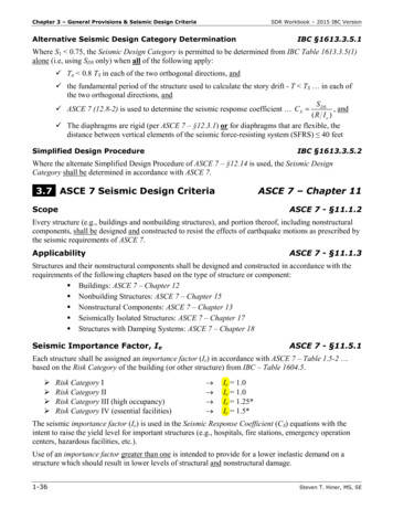
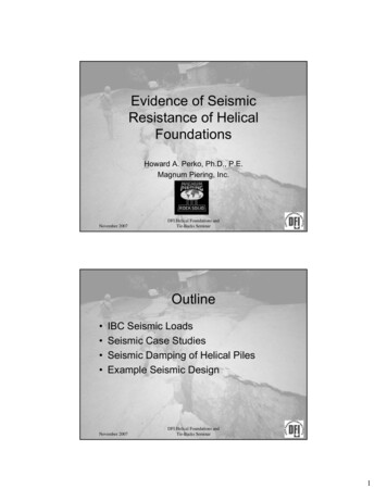
Changes in Design Response SpectraChapter 11 of ASCE 7-16 defines a design spectrum using only two points (anchor or control points), SDSand SD1, which are derived using Fa and Fv site coefficients. This “standardized” shape has acharacteristic flat top at shorter periods and decreasing spectral accelerations at longer periods wherethe corresponding velocity spectrum is relatively constant. Technically, there is a third control pointabove which the shape of the spectrum is displacement-based when plotted on a tripartite plot. Basedon maps provided in the code, this point, TL, is commonly 6 to 8 seconds for most of Utah.GMPEs used in GMHAs create smoothed, multi-period spectra. Studies have shown that multi-periodspectra developed using GMHA per Section 21.2 of ASCE 7-16 for Site Classes A, B, and C are generallyconsistent with the code-based design spectra developed following the procedures of Chapter 11 ofASCE 7. However, comparisons with multi-period GMHA spectra for Site Classes D and E (i.e., less stiffsite conditions) show code-based spectra developed using Chapter 11 of ASCE 7-16 to beunconservative, especially at mid to long periods. These concepts are illustrated in Figures 1 through 3,derived from spectra shown on the FEMA P-1050-1/2015 Edition document, NEHRP RecommendedSeismic Provisions for New Buildings and Other Structures (BSSC, 2015). For the purposes of theimmediate discussion, the MCER spectra shown in the figures may be ignored, and focus placed on thedesign spectra. It can be seen that disparities exist between the black-colored “ELF design spectrum”(which is in essence the current ASCE 7 standardized shape design spectrum without the initial risinglimb) and the cyan-colored “design multi-period response spectrum” which is based on a set of GMPEsapplied to a wide range of periods. In the three figures, it can be seen that the current design spectrumis increasingly unconservative with the cyan curve plotting above the black curve as the sites becomeless stiff (i.e., site class change from C to E).Page 6 of 18
Figure 1 – Comparison of ELF and Multi-Period Spectra, Site Class C (from FEMA P-1050-1; BSSC, 2015)Figure 2 – Comparison of ELF Multi-Period Spectra, Site Class D (from FEMA P-1050-1; BSSC, 2015)Page 7 of 18
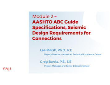
Figure 3 – Comparison of ELF Multi-Period Spectra, Site Class E (from FEMA P-1050-1; BSSC, 2015)The updated provisions of ASCE 7-16 prescribe Fa and Fv values targeted toward overcoming theunconservative spectra. This is accomplished in two ways. First is to require GMHA for all sitesdesignated as Site Class D or E with S1 greater than or equal to 0.2 and/or for Site Class E sites with Ssgreater than or equal to 1.0. The GMHA-based approach calculates design spectra based on a sitespecific Vs30 and other characteristics of the site, not on the code provided values of Fa and Fv. Using aGMHA provides spectral acceleration values (but not site coefficients) for each period at whichcalculations are performed (which is typically about 22 periods distributed logarithmically over a rangeof 0 to 10 seconds for most GMPEs). Not only does a GMHA provide a more refined and realisticspectral shape, it is believed that in many cases, the design spectrum will be less than the exceptionsallowed by ASCE 7-16 (as described next and Topic #3 later on in this document).The second way of overcoming deficiencies of the simplified design response spectrum from previouseditions of ASCE 7 for Site Class D and E sites with high acceleration levels is to use the exceptionsprovided in ASCE 7-16 which allow designers to use the published values for Fa and Fv with adjustmentsthat increase spectral acceleration values for both short and long periods. The result is thataccelerations for short period buildings may increase by as much as 20 percent (using Fa taken as equalto that of Site Class C) and accelerations for longer period buildings may increase by as much as 50percent (increasing Cs by 1.5 on Site Class D sites when building period is greater than 1.5xTs). Theseincreases are meant to account for site response that is not captured unless a GMHA is performed.Hence, project stakeholders have the option of foregoing the GMHA, but the prescribed design forcesfor Site Classes D and E may be higher. Whether this option is prudent is a decision that must be madePage 8 of 18
on a case-by-case basis in as the majority of structures where the exception would be applied aretypically shorter-period buildings that are not likely to be affected by the potential 50% increase for SiteClass E or an extended flat-top region for Site Class D.Site Class F sites (which include sites having liquefiable soils; highly organic soils; very high plasticityclays; or very thick, soft to medium stiff clays [see ASCE 7-16, Section 20.3.1 for more defining details])must have a site response analysis (SRA) performed. The base rock input ground motion for the analysismay be matched to spectra from Chapter 11 of ASCE 7-16 or from a GMHA. An SRA is also allowed to beused to define ground motions for any site class. One important exception to needing to perform anSRA for a liquefiable Site Class F site is in the case of structures having a fundamental period of0.5 seconds or less (see ASCE 7-16, Section 20.3.1). Other exceptions exist for the non-liquefiable sitetype categories within Site Class F.RECOMMENDATIONS FOR UTAH SEISMIC DESIGN PRACTICEIn developing the workshop, committee members discussed a range of issues (some new and some notso new) associated with the updated design provisions of IBC 2018 and ASCE 7-16 related to seismicground motions. These issues were framed into questions which would serve as discussion points forthe workshop panel session. Since the time of the workshop, other potential points of discussion haveemerged as local engineering professionals have attempted to embrace the new seismic designrequirements. The original questions formulated by the committee have been restructured herein as“Topics” to facilitate a written format and accommodate subsequently added thoughts. One particulartopic (Topic #5) addresses the qualifications of those performing GMHAs and SRAs. Another topic (Topic#6) addresses what a report presenting the results of a GMHA or SRA should contain. It is the opinion ofthe authors and committee members that this document reflects generally sound seismic designpractices, which when followed will help achieve sound seismic designs and provide the public withmeaningful measures of seismic risk mitigation. It is hoped that this document will also impress uponreaders and practitioners the committee’s view that performing a GMHA and SRA is not a trivial matter.Topic #1: When Should a Site-Specific Seismic Study Be Performed? In short, a site-specific seismicstudy (GMHA and/or SRA) can be performed for any site. Excluding certain types of structures, as statedpreviously, a GMHA is required in the case of a site classified as D or E with a mapped S1 parametergreater than or equal to 0.2 s, or in the case of a site classified as E with a mapped Ss parameter greaterthan or equal to 1.0 s. An SRA must be performed in the case of a liquefiable, Site Class F, site. An SRAis also required for the other subsurface conditions constituting Site Class F, these being highly organicsoils; very high plasticity clays; or very thick, soft to medium stiff clays. However, the code documentsallow exceptions to these GMHA and SRA requirements in certain instances (see ASCE 7-16, Section11.4.8 and 20.3.1). Besides the explicit requirements of the code, it is strongly recommended that aGMHA or SRA be performed anytime when the structure represents a critical lifeline component. Whilenot required by code, it is strongly recommended that a GMHA or SRA (with the former sometimesbeing preferred, all other things being equal, due to the latter’s greater complexity and potential forerrant results) be performed for all Risk Category III and IV structures. This reflects a philosophy thatsituations presenting greater risks merit more robust methods of analysis (or at least greater certainty inthe representativeness of design parameters). In any event, the geotechnical and structural engineersPage 9 of 18
of-record should engage early in the design process by having a discussion regarding the seismic designof the structure to identify and develop a seismic design strategy for the structure.Topic #2: Geotechnical Site Data Needed for a GMHA or SRA. As a general introductory statement, itshould be recognized that additional field and laboratory data are usually required to complete an SRAas compared to a GMHA, and both types of analyses require information which has not beenconsistently collected in past geotechnical engineering practice that may have been strictly focused ondeveloping foundation and earthwork recommendations. Owners and Clients need to be prepared for agreater commitment of resources when a GMHA or SRA is required instead of the standard seismicdesign spectrum. Shallow geotechnical data alone are insufficient to classify a site with respect to itsanticipated seismic response or correctly perform a GMHA or SRA.The standardized code-based spectrum is based on a seismic site class which is associated with aparticular range of Vs30 values (or alternately [and less preferably] SPT blowcounts (N-values) orundrained shear strengths). Vs30 is the weighted, harmonic mean (not the arithmetic average) of shearwave velocity of the top 30 meters (or alternately the top 100 feet) of the subsurface profile. It isimportant to recognize that criteria in addition to shear wave velocity (or SPT blowcounts or undrainedshear strength, by proxy) exist for evaluating potential site classes of E and F (see ASCE 7-16 Section 20.3and Table 20.3-1). In particular, a site classification of E exists with any profile having more than 10 feetof soil with a plasticity index (PI) of more than 20, a moisture content of 40% or more, and an undrainedshear strength of less than 500 psf within the upper 100 feet of the site). Locally, certain deep-lakedeposits of Lake Bonneville will sometimes present a site classification of E, even when the Vs30 valuesexceeds the threshold of 600 ft/sec for the class. Relative to this topic, it should also be noted thatwhile SPT blowcounts or undrained shear strength may currently be used to evaluate site class, itappears likely that such options will be disallowed in future versions of seismic code documents.For a GMHA, specificity greater than that provided by one of six site classes (A through F) is needed todescribe the site response, and a Vs30 value (rather than a site class) is used directly in calculations. In anSRA, even more detailed characterization of subsurface conditions is required, with a shear wavevelocity (or alternatively a low-strain shear modulus) being assigned to each individual subsurfacestratum (soil layer). Hence, one can see that there is a progression in the specificity and rigor with whichsubsurface data are collected and conditions are characterized as the methods of analysis become morecomplex.As indicated above, as a minimum, a measured Vs30 value is recommended for a site-specific analysis.Given that some geotechnical site investigations focus on shallow foundations and the method of fieldexploration may only consist of test pits, the question naturally arises as to how to assess deeper stratain order to obtain Vs30. This issue existed to some degree before adoption of the new codes. In the past,some engineers relied upon deeper data from adjacent sites while others considered the geologicsetting and/or maps of geology-based site response units such as that of McDonald and Ashland (2008).In some measure, this may be acceptable in the case of non-site-specific based design response spectrain the code because a site class need only represent a range of potential values. However, for sitespecific studies, the Vs30 value is a discrete number or perhaps even a range of measured values.Regardless of whether a site class or Vs30 value is used to assess seismic effects, individuals who quantifyPage 10 of 18
and present ground motions for design should clearly indicate the basis for the values used in theiranalyses.There are several options available for measuring shear wave velocities as needed to perform groundmotion studies. More obvious means are test holes or cone penetrometer test (CPT) soundings whichextend to a depth of 100 feet, coupled with downhole (or in the case of test holes, even cross-hole)shear wave velocity measurement. One relative advantage of the CPT method is not only can shearwave velocity measurements be made at the same time, undrained shear strengths which maydifferentiate Site Class E from D are readily obtained by fairly reliable published correlations.Geophysical means such as spectral analysis of surface waves (SASW), multichannel analysis of surfacewaves (MASW), or microtremor array measurement (MAM, also popularly referred to as refractionmicrotremor or ReMi) can also be effective means of measuring shear wave velocities. It isrecommended, however, that geophysical surveys only be performed by knowledgeable andexperienced individuals. MASW and MAM methods have certain depth and resolution limits which, insome instances, make them inadequate for purposes of site-specific seismic studies, particularly SRAs.One might note that there can be a range of measured values using different methods for the same site.However, committee members believe that the effect of those differences will be much less than othervariabilities, including the variances between individual GMPEs.Shear wave velocities should be measured over multiple depth increments in order to assess potentialimpedance contrasts present in the subsurface profile. (This means that a single shear wavemeasurement at the bottom of a deep CPT sounding is an inadequate means of site characterization). Ifa site presents a large, near-surface impedance contrast (such as loose/soft soil over sound bedrock),conventional use of Vs30 values to obtain site coefficients based on site class or ground motionprediction equations (GMPEs) as implemented in a GMHA may not be valid. Also, except perhaps atshallow rock sites, test pits alone, because of their limite
The 2018 International Building Code (IBC 2018), and by extension referenced provisions of ASCE 7-16, was adopted July 2019 by the State of Utah. ASCE 7-16 introduces significant changes to prescribed seismic forces for the design of structures when compared to IBC 2015 and ASCE 7-10. These changes include updated mapped B/C boundary seismic .