Transcription
Sonic Farm Pro Audio,Vancouver, BC, CanadaTel 310-402-2390, 778-863-1613www.sonicfarm.comfor email, please use contact box on our websiteSonic Farm TantraBass PreamplifierUSER MANUAL
Dear Audio Professional,Thank you for purchasing the Tantra. We hope it will deliver exceptional performance for many years into the future.Please take the time to read this manual. It describes Tantra’s design philosophy as well as its most important functions.DESIGN PHILOSOPHYAt the heels of the success of our 2DI4 Pentode direct box, a conversation arose to build a full-blown bass preamp with extensive functionsand an optional high power module capable of fulfilling the needs of today’s professional bass player community.The idea came from a fellow pro-audio designer and a lifelong pro bass player Michael Arnopol. He thought that the 2DI4, as good as itsounded, needed to be taken to the next level. After some initial resistance and a lot of brainstorming between Boris, Michael and me, wewarmed up to the idea, and over the course of almost a year, came up with the design you are now seeing in front of you, the Tantra.Apart from the unchanged pentode input section borrowed from the 2DI4, the preamp has an overdrive section, centered around anotherpentode, followed by several solid-state powered sections: a high-pass filter, a 5-band EQ, a compressor and a 2-part harmonic generator.There are effects loop points (send and return, balanced or unbalanced) that facilitate adding external effect units to the signal chain.Both the DI and line outputs are still there, just like with the 2DI4, with some important functions added.There is a place to house and connect an optional ICE1000ASP class D power module as well. This module was suggested to us by the basscommunity as the one with the best sound, power, impact and clarity amongst all of the available ones today.All of the sections were optimized for use with a bass instrument, although the unit can be successfully used with other types of signals aswell.The idea was to essentially have a 2DI4 along with all these other sound processors that would have “no sound of its own” and thus not takeaway from the definition and richness that the 2DI4 is known for. We hope we have fully succeeded in accomplishing that. In addition, allsections can be bypassed, and when they are, one essentially gets the barebone 2DI4 sound.We hope you will put this preamp through it’s paces both in your studio and at your live gigs and that it will give you many years of fulfillingperformance!
SOME REMINDERS REGARDING TUBESTubes work with very high supply voltages. There are points inside Tantra that measure in excess of 350V DC. If touched, those voltagescould be lethal!Make sure that no pointed objects (especially metal) or liquids penetrate the inside of the unit through its cooling grilles or otherwise. If thataccidentally occurs, immediately pull the plug out of the power socket and wait for the unit to discharge. Tantra must not be operated ifmoisture penetrates inside.Before opening the unit one must disconnect the mains cord and then wait several minutes for the internal capacitors to discharge.When mounting in a rack enclosure, always leave an empty space above the unit to ensure proper cooling.Please do not replace the mains fuse with one of a higher value: use only slow-blow types rated 630mA@110-120V or 300-350mA@220240V.Legal Disclaimer: Neither Sonic Farm nor anybody associated with it can take any liability for damage to persons or property caused byeither use, modification or servicing this unit.HOW TO CHANGE TUBESThis only applies to a functional unit. Please entrust any repairs to qualified service personnel.Only an EF-86 or EF-806/EF-806S (or equivalent, like 6267, 6CF8 or Russian 6J32P) pentode can be used.Pull out the power cord. Wait for at least 10 minutes for all the capacitors to discharge.The left tube will influence the tone more than the other one, which will only affect the overdriven signal, when blended in. Both tubes are ofthe same type and can be replaced when worn out or if a slightly different tonal texture is desired.Remove Tantra’s cover by removing all of the screws on the cover.Pull out the tube while adding a subtle but fast left-right motion to loosen the tube from a tight socket. Do not bend the tube much out of theaxis because you can break the pins or cause air to enter the tube and destroy it. Paying attention to the pin alignment, push the replacementtube into the socket using same motions but in the opposite direction. Make sure it goes in all the way.Due to electric shock danger, testing the preamp with the lid removed is not recommended. Screw the cover back in place and you’re done.
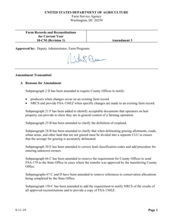
TANTRA’S FRONT PANEL CONTROLS:1Instrument ¼” input. Plug your bass (or guitar, keyboard instrument) here. The input impedance is 2.2MΩ.2Trim controls determining the level of Lo and Hi boost. Up to 9dB in pentode and 5dB in triode tube mode. This boost happens on thefirst, clean tube stage, and will affect everything else down the chain. Use a mini slot (.098”/2.5mm Ø, .031”/0.8mm wide) or hexscrewdriver (.104”/2.64mm hex x .055”/1.4mm deep) to adjust pots.3The first group of mini toggle switches starts with the DI feed switch. It determines what goes to the DI output (which, of course ismic level). Left: DI is fed from the point after the tubes, and will be affected by the tube mode (pentode/triode, switch 6), Lo and Hiboosts (5 and 7), the attenuation/mute switch (4), clean gain (8), overdrive gain (17) and overdrive blend (10). Right: DI is fed fromthe output of the preamp and is affected by all processing, including the master level pot.43-position attenuation/mute switch, works at the point after the tubes and before the effects loop. Left: mute. Must use beforechanging tube modes to avoid a loud click caused by re-biasing of the input tube. Most speakers are sensitive to such clicks as well.Middle: no attenuation. Right: 6dB attenuation of the signal; use with stomp boxes in the FX loop to avoid overloading them.
563-position Lo boost switch. Left: Bass boosted (shelving type) at first tube. Max 9dB (pentode) and 4dB (triode), depending on theleft trim pot setting. Middle: no boost. Right: overall gain boosted, use with very quiet basses or to get more overdrive at the 2nd tube.Tube mode switch. Left: pentode. More gain and subtle saturation. Right: Triode. Less gain and cleaner, more polite sound.73-position Hi boost switch. Left: Treble boosted (shelving type, starting at about 2kHz) at first tube. Max 9dB (pentode) and 4dB(triode), depending on the trim pot setting. Middle: no boost. Right: Treble boosted (shelving type, starting at about 4kHz).8Clean gain mix control. This is post the first tube and will affect everything down the chain (not including the OD tube). It is desirableto have this control as high up as possible without clipping the subsequent stages. You will be watching the bi-color overdrive indicatorLED (9) with the switch (14) in the right position. You don’t want this LED to turn red even at the loudest notes played. Please notethat whereas the tube front end breaks up very musically when overdriven, this not the case with the solid state processors followingthe FX loop return. They clip in a very unpleasant and jarring way. (See explanation under 14 to make this even more clear) Also seecompressor explanation.9Bi-color overdrive indicator LED (9). Green for signal presence, turns red to show clipping distortion. It can show a clipping on the firsttube or elsewhere in the chain, depending on the OL feed switch (14), please see explanation.10 Overdrive blend pot: mixes the overdriven signal coming out of the 2nd tube with the clean one from the 1st. This OD blend can bemuted using a foot switch, see rear panel guide. The small orange LED (11) comes on when foot switch muting is active.11 OD mute switch indicator (orange LED). Above it is a blue LED that just indicates that the preamp is ON.12 OD switch activates the 2nd overdrive stage (uses FET’s). Left: 2nd OD stage active through a high-pass filter. Middle: 2nd OD stage notactive. Right: 2nd OD stage full on.13 Effects loop activation switch: Left: FX out. Right: FX in. Make sure this one is pushed to the left with no FX connected, otherwise therewill be no sound.14 Overload indicator feed switch. Left: Indicates a possible clipping distortion on the first tube. Gain pot (8) will not affect this. Good toknow if you are clipping the first tube with a very loud (high signal output) bass. Switch to Triode to avoid it. Deactivate any boost (5and 7). This should accommodate even the loudest existing basses. If your signal (maybe a keyboard) still clips the input tube, reducethe output level on the instrument itself. Right (and this is where the switch should normally be): OL indicator monitors the signal justprior to the master level control. Bypassed sections affect neither the sound nor this indication. Clipping at those solid state stagessounds nasty and should be avoided. Use the clean and OD mix controls to adjust.15 Pre OD high-pass filter switch. It will affect the overdriven tone. Left: some bass filtered out to avoid mud. Middle: only mids and treblefrequencies pass into the OD tube (use for rock and roll crunch sound or to get more bite out of your bass). Right: full on (think LarryGraham, “Dance to the Music”)
16 Compressor switch. Left: out. Right: in.17 Overdrive gain control, determines how hard you drive the 2nd tube. Good to keep this at minimum if you are not using overdrive.18 High-pass filter switch. Left: out. Right: in. This is the first processor after the FX loop.19 EQ switch (separate from the HP). Left: out. Right: in. EQ is the second processor, following the HP.20 HP filter frequency: Left: 28Hz. Middle: 60Hz. Right: 40Hz.21 Bass shelving gain (boost or cut, detents in the middle for flat), part of the EQ section.22 Center frequency of the first parametric band filter, 34 to 300Hz. Note that controls affecting the same parametric band filter sectionare connected by red lines for easy action)23 Center frequency of the 2nd parametric band filter, 150 to 1300Hz.24 2nd parametric band gain (Boost or cut, flat in the middle). Max boost or cut will interact with the Q2 control (the width of the curve or,to be more precise, the resonance peak or dip intensity). This applies to all 3 parametric bands.25 Center frequency of the 3rd parametric band filter, 690 to 6000Hz.26 3rd parametric band gain (Boost or cut, flat in the middle).27 3rd parametric filter band’s Q control (resonance or width). The filter will have a narrower and more intense peak or dip, depending onthe G3 setting.28 2nd parametric filter band’s Q control (resonance or width).29 1st parametric band gain (Boost or cut, flat in the middle).30 1st parametric filter band’s Q control (resonance or width).31High frequency shelving control, boost or cut, flat in the middle)
32 Compressor drive control. For the main signal chain, with no harmonics blended in (see 34 or 35), the compressor switch (16) needs tobe flipped right for this compression drive control to be active. You are hitting a fixed compression threshold (the level wherecompression kicks in) with more or less signal, which affects the overall loudness as well as the point in time (from plucking a string allthe way to decay) where loudness starts to be “shaven off”. For studio heads, the compression ratio is fixed to around 3.5 to 4, and therelease time is optimized for bass instruments. This compressor also features a special, dual time constant, feedback circuit. In plainwords, it won’t pump or breathe or squash your attack even at higher settings. Even slapping will yield clean, distortion-free, naturalattack. It rivals best studio compressors, and then some. It is important to point out that the signal should be nice and strong (usecontrols 8 and 10) to get the most out of the compressor. Just make sure you don’t get red clipping with OL fd (14) switch in the rightposition. The dB markings around the dial indicate maximum gain reduction possible in that setting.33 Master level control. Affects line output, as well as the power amp, if built in.34 2nd harmonic blend. This section allows giving your bass a bit more “growl”. The effect is limited to low and low-mid frequencies only.The nature of this circuit makes it emphasize louder notes. That’s why we left the compressor permanently engaged with these 2harmonic generators, so that you can regulate not only the blend, but also the intensity of harmonic generation (even with thecompressor switch flipped to the left). With compressor drive at minimum, the effect will be subtler, and you will need to blend in a bitmore. As you turn up the compressor drive, the effect will start to be more intense, so adjust to taste. This blend control mixes theharmonic generator output with the main signal.35 4th harmonic blend. The same as above applies here. The only difference is the sound of the 4th harmonic.
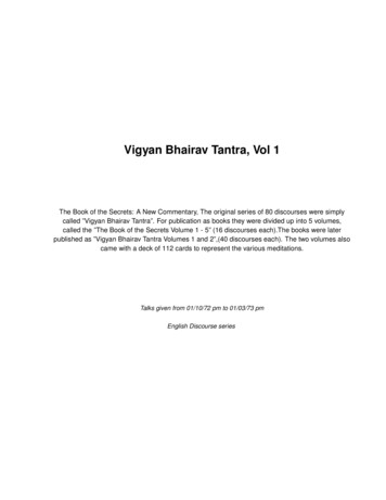
TANTRA’S REAR PANEL CONTROLS:36 Standard IEC-type power receptacle. Just make sure that the fuse ratings correspond to the mains voltage you are using.37 and 38: Voltage selectors for power amp and preamp separately. These are 2 different circuits; make sure both are set to the correctmains voltage.38 See above.39 and 50: Speaker “Speakon” connectors. Active only when the power module is built in. Use only the proper Speakon cables. Totalminimum speaker impedance not to go under 4Ω (Ohms). This is the same as 2 x 8Ω. Of course, you can use a single 8Ω or a 4Ω speakercabinet. The maximum output power will be 1000W into 4Ω or 500W into 8Ω.40 External power amp input. Active when the pushbutton switch (41) is depressed.41 Press to activate the external power amp input and separate the preamp from the power amp. The line preamp output will still beactive. You can even insert an external (balanced, studio grade) processor in between the preamp line output (42) and the power ampexternal input (40). For normal amp operation, this switch should be out (not depressed).
42 Line level balanced output (electronically balanced). (XLR pin connection: 1 GND, 2 HOT, 3 COLD). Useful for recording or driving anexternal power amp. IMPORTANT: If you want to drive an unbalanced input, you need to make a special XLR to ¼” cable: ConnectXLR’s pin 1 to ¼” plug ground (sleeve) and connect XLR’s pin 2 to ¼” plug tip. Leave XLR pin 3 disconnected (floating). You cannot usethis cable on the DI output, only on line out.43 Ground lift switch. Press to prevent hum caused by ground loops (only when the line output is connected to another unit and you get ahum as a result). This function cannot remove hum already present in the instrument signal (for example your bass pickups picking uphum). Under normal operation, this switch should be out.44 DI (or microphone level) output (Transformer balanced). Balanced connection only! (XLR pin connection: 1 GND, 2 HOT, 3 COLD).45 Overdrive blend disable footswitch. Use a standard latching ¼” foot switch that connects tip and sleeve when engaged.46 Effects send jack, tip-ring-sleeve. Can be used for unbalanced effects (only when switch 47 is out), or balanced (switch 47 pressed). Youmust reduce the signal level when you use unbalanced stomp boxes not to overdrive them. Flip the attenuator switch left, or, if that isnot enough, reduce the (8) and (10) controls.47 This switch chooses between unbalanced effects connection, like stomp boxes, or balanced (studio units with XLR connectors). Out forunbalanced, in for balanced. When in balanced mode, jacks (46) and (48) are in TRS mode: Tip: Hot, connect to XLR pin 2; Ring: Cold,connect to XLR pin 3, and Sleeve: Ground, connect to XLR pin 1.48 Effect return, balanced or unbalanced, depending on the switch (47) setting. Remember that the FX loop is activated from the frontpanel, switch (13).49 Tuner output, mono ¼” jack.50 See 39.51 Preamp fuse, 630mA@115VAC or 300-350ma@220-240VAC. Replace only with a slow blow fuse of the same rating for the appropriatemains voltage.52 Ditto, power amp fuse. 10A@115VAC, 6.3A@220-240VAC. Do not exceed these ratings.53 Preamp power switch. You can use the preamp separately from the power amp (when built in). With the integrated version, alwaysturn the preamp first (before the power amp), and turn it off last (after the power amp).54 Power amp power switch. On the front panel, to the right and above the F3 control (25), there is a small red LED. This is the power ampclipping indicator. If this LED occasionally lights up, it means you are driving the power amp too hard. Reduce the master level.
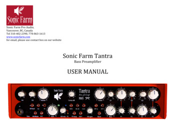
Tantra’s Functional Block Diagram:
TECHNICAL SPECIFICATIONS:1 channelFrequency response: 10Hz-50kHz /- 3dBMaximum gain: 54dB at the line output, 32dB at the DI (mic level) outputHarmonic distortion: 2% before clipping level, quickly decreases if driven less.Maximum output level: 30dBuMinimum output load: 600ΩConnectors: XLR DI and line output, balanced onlyInstrument input: 1/4” unbalanced, monoPower consumption: 30W preamp, max 1100W power amp.WARRANTY INFORMATIONSonic Farm gives a one-year warranty on parts and labor from the date of purchase.Should you need to send in your unit for warranty-covered service, please contact us for an RMA number first.We will also tell you where to send the unit.Any Modification of the unit voids the warranty.CONTACT INFORMATION:Sonic Farm Pro Audio,Vancouver, BC, CanadaTel 310-402-2390, 778-863-1613www.sonicfarm.comFor email, please use contact box on our website
Sonic Farm Pro Audio, Vancouver, BC, Canada Tel 310-402-2390, 778-863-1613 www.sonicfarm.com for email, please use contact box on our website Sonic Farm Tantra