Transcription
SPE Distinguished Lecturer ProgramThe SPE Distinguished Lecturer Program is funded principallythrough a grant from the SPE Foundation.The society gratefully acknowledges the companies that supportthis program by allowing their professionals to participate aslecturers.Special thanks to the American Institute ofMining, Metallurgical, and PetroleumEngineers (AIME) for its contribution tothe program.Society of Petroleum EngineersDistinguished Lecturer Programwww.spe.org/dl1
Why Coiled Tubing Fails and How toAvoid Failure on Your Job. in Your WellorWhy Coiled Tubing Works and How toMake Sure it Works on Your Job. in Your WellSteven M. TiptonThe University of TulsaSociety of Petroleum EngineersDistinguished Lecturer Programwww.spe.org/dl2
The Oilfield is a Rough Place3
Outline Introduction / Mechanics Primer CT Fatigue Research– TU Coiled Tubing MechanicsResearch Consortium Surface Defects Analytical Modeling– FlexorTU5 Inspection– 3D laser imaging4
Background 1989 - developed CoilLIFE – Schlumberger 1994 - JIP to revise CoilLIFE and developCT test machine 1995 - developed coiled tubing fatigue module forNOV-CTES (Achilles) 1996 - 2000 University of Tulsa JIP’s to studyCT mechanical and fatigue behavior 2000 – present: University of Tulsa Coiled TubingMechanics Research Consortium5
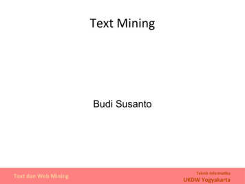
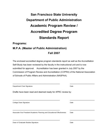
What is “Coiled Tubing” Exactly what it sounds like Continuously Milled Tubing Rolled from Flat Strip– Resistance Welded Seam– HSLA (High Strength Low Alloy) 55-120 KSI– CRA Chrome Alloys, Titanium Diameters: 0.75” – 4.5” Thicknesses: up to 0.25” Lengths 30k ftCourtesy Quality Tubing– 10K – 20k ft most common6
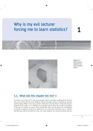
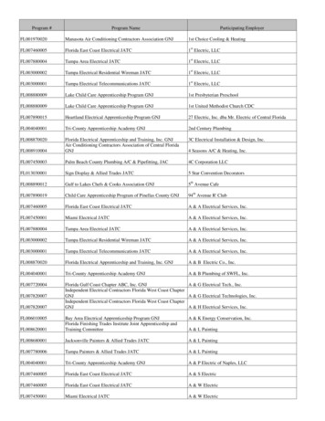
Typical CT RigupWhat is it used for? Anything “jointedtubulars” are used for! Drilling“Gooseneck”Coil TubingGuide ArchInjector Completion ServicingReel 10-20K ftCourtesy ICoTA7
Coiled Tubing Units8
Coiled Tubing2009 SAE Baja Vehicle9
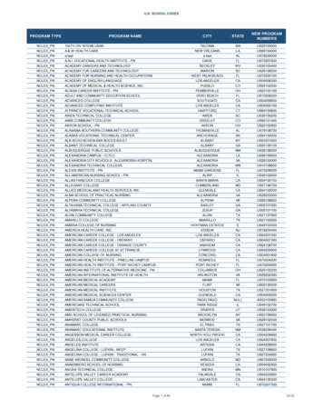
Bending StrainsTop material inTENSIONBottom material inCOMPRESSION“Strain” defined as % material stretchesin Tension or shortens in Compression10
Bending Cyclesspool repeats each tripstrainspoolarch archstraight hole straighttime11
Bending Strains Lead to ULTRA-Low Cycle Fatigue– e.g., lives 10 – 100 cycles to failure Normal Low Cycle 103 Cycles to Fatigue Engine Parts 106 Cycles to Fatigue Ballooning– 30% even when pressure is 50% yield Permanent Elongation– 6-10 ft per 10,000 ft trip, even for axialloading well below yield12
Bending StrainsHuge Cyclic Plastic Strains ( 2%!)Even withpressure below50% of yieldbending axis“Ratcheting”Incrementaldiametergrowth 30%Lives 10 cycles!Wall Thinning13
Permanent Elongation14
Bending Strain DistributionStrain15
Bending Strain Distributionεx,m r/RrStrainR16
Bending Stress Distribution-SySyStress17
Bending Stress DistributionSy-SyStress18
Causes Permanent ElongationFStress19
CT FatigueResearchCoilLIFEFatigueTestMachine20
CT FatigueResearchCoilLIFEFatigueTestMachine21
CT FatigueResearchCoilLIFEFatigueTestMachine22
TU CT Fatigue Test Facility23
Accelerated CT Fatigue Test Machine24
Fatigue Crack Development5 4 3 2 1NUMBER OFFAILURES1 2 3 4 5 6 7 8NUMBER OFFAILURES25
Fatigue Crack DevelopmentMOST fatiguecracks initiateat the inner surfacecross sectionthrough tubing wallFatigue behavior of CTdefies engineering logic!Appears asa “pinhole”failure26
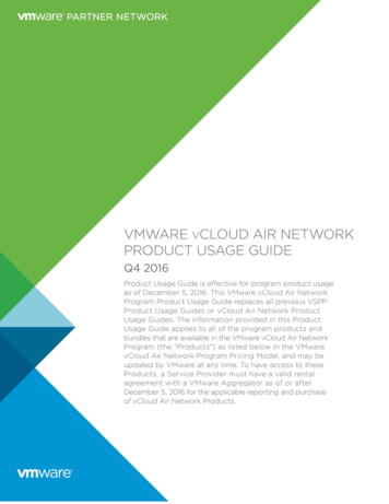
120 ksi, 1.5" x 0.134" x 48"R500CT Life Prediction Routine450Cycles to Failure40035030025050% (mean) prediction20015010095% confidence Pressure (psi)27
CT Life Prediction Factors that influence life:– Diameter Larger diameter – larger bending strains– Pressure Higher pressure – higher tangential stresses– Wall Thickness Thinner walls – higher tangential stresses– Bending Radius Spool GooseneckSmaller radius – larger bending strains– Material Grade70 – 120 ksi28
Effect of Tubing Diameter29
Gooseneck Radius of Curvature30
Material Selection31
Fatigue Life EstimationLCFTestingConstant PressureFixtureTestingComplexField LoadingεxεxtimePFittingRoutinePlasticity / FittingRoutinetimeinputinputMATERIAL DATA SETLCF Dataσf’, b , εf’,E’, K’, n’outputCoil Tubing ParameterS f(σh, Sy’, Δεx)CT Fatigue ModelDtime32
CT Life Prediction Implemented with String Management Software:100Fatigue Life Profile% Life Expendedwarning level0Distance along String Fatigue eliminated as a primary failure mode!33
What About Defects?34
Means of Imposition Milling (cut into surface) Impressing Corrosion Pits (chemical milling) EDM – Different shapes possibleadxbcdefghiw35
Means of ImpositionMilled BallImpressed Ball36
Influence of Surface DefectsLow Pressure Impressed vs Milled 1/8" Balls2.375” 80 ksi tubing, tested on 72” radius fixture%DefectBaselineLifeRatio .4Impressed (t 0.156)Milled (t 0.156)0.2Impressed (t 0.204)Milled (t 0.204)000.050.10.150.20.250.3d/tDepth / Wall ThicknessRatio0.350.40.4537
Repairing Defects What happens after adefect is discovered?– Scrap / Replace string(expensive)– Cut and splice (welding –expensive)– Grind repair38
Repairing DefectsOne Option: Butt WeldingUnfinished inside of the buttweld constitutes a severestructural discontinuity!39
Butt Welding Fatigue Data% of Unwelded Sample Life908070Manual Welds:average 38%std. dev 18%Orbital Welds:average 41%std. dev 11%605040Manual AverageOrbital Average302010040
Grind Repairingreplaced withAbrupt, localized discontinuitysmooth, gradual thickness changeTechnique is important and grind repairguidelines have been developed41
Fatigue Life Predictive ModelNo defect:229Cut defect:76Repaired:129Impressed:21442
Defects Must be FOUND Visual Inspection Magnetic Flux Leakage– Most popular approach for CT inspection– MFL can only DETECT defects– Can’t provide any information about defectsize or severity 3D Laser Imaging for NDE– Complete geometry of defect is captureddigitally43
3D Laser Imaging System(Low-Cost)Longitudinal Milled Defect44
Commercial Laser SystemSawcutMilled ballImpressedballMilledCylinder45
Color-coded Digital DataImpressed ballMachined ball46
Automated Defect MeasurementsdwAprminrmax47
Color-coded Digital Data &Photographic ImageUseful todistinguishcut orimpressed48
Sour and Corrosive Environments Similar effects: CT to Pipe H2S HIC (Hydrogen Induced Cracking) SSC (Sulfide Stress Cracking) SCC (Stress Corrosion Cracking) Residual Stresses Accelerates Corrosion49
Manufacturing and Materialsdefects/flaws From 7 to 20 reels per1,000 reels ( last 3 yrs)–0.7 to 2%–Only Those Reported‘Cold’ Weld Failures occur that arenot fully investigated–Especially later in CT LifeCourtesy BJ Services50
Conclusions Fatigue is inherent to the use of CT Large CT Bending Strains Cause– Fatigue, diameter growth, elongation Scatter is Associated with Fatigue Data Fatigue Software can Predict Influence of– Material, diameter, wall thickness, bending radius,internal pressure, statistical scatter, defects, grindrepairs Field Monitoring Software used to AssessEvery Section of Tubing Along the EntireString – Avoids failures in the field51
Conclusions Defects can have first order influence (cut)– Or negligible influence (impressed) Repairing by Grinding is a viable option Software helps to quantify defect severity(and effectiveness of a grind repair ) 3D Laser Scanning– Holds the potential to detect defects– Capable of measuring every detail about theirgeometry52
ConclusionsTo Avoid Failures on Your Job. or In Your well: Control the Factors that Contribute toFatigue Damage Accumulation– Minimize tubing diameter– Maximize spool andgooseneck sizes– Select material mostsuited for application– Minimize tripping– Minimize tubing movementwith high pressure53
Conclusions Avoid Defects– Eliminate sources ofdefects - handling,injector debris – Monitor/Inspect– EnvironmentallyInduced Cracking Storage corrosion– Repair shallow defectusing grind repairtechniques54
WhyWhyCoiledCoiledTubingTubingSucceedsFails andandHowHowtoto AssureAvoid FailureSuccesson onYourYourJobJob. in Your WellSteven M. TiptonThe University of lsa.org55
Your Feedback is ImportantEnter your section in the DL Evaluation Contest bycompleting the evaluation form for this presentation orgo online at:http://www.spe.org/events/dl/dl evaluation contest.phpSociety of Petroleum EngineersDistinguished Lecturer Programwww.spe.org/dl5656
What is “Coiled Tubing” Exactly what it sounds like Continuously Milled Tubing Rolled from Flat Strip – Resistance Welded Seam – HSLA (High Strength Low Alloy) 55-120 KSI – CRA Chrome Alloys, Titanium Diameters: 0.75” – 4.5” Thicknesses: up to 0.25”