Transcription
4E0TRANSISTORAUDIO AMPLIFIERMANUALbyClive Sinclair32 practical transistor amplifier circuits.Complete parts list and full constructionaldetails.111Amplifiers ranging from 50 micro -watts up to75 watts output.33 layout and constructional diagrams.Comprehensive servicing data.Practical hints and tips on construction.Amplifiers for hearing aids, pocket radio sets,tape recorders, record players, tableradios, etc.Choice of amr piers for specific requirement.High fidelity amplifier design.Servicing and fault finding, etc.BERNARD'S RADIO MANUALS
TRANSISTORAUDIOAMPLIFIERMANUALbyCLIVE SINCLAIRBERNARDS (PUBLISHERS) LTD.THE GRAMPIANSWESTERN GATELONDON W.6
FIRST PUBLISHED FEBRUARY, 1962Reprinted July, 1963.Reprinted November, 1964.Reprinted August, 1966.Reprinted January, 1969.Reprinted July, 1970.Reprinted May, 1972.16.IP) 4.11NIAACKNOWLEDGEMENTWe must express our grateful thanks to G.E.C.Limited, Mullard Limited, Newmarket, Limited,and the University of Cincinnati for their kindco-operation in supplying us with informationwithout which this book would not have beenpossible.We invite all authors, whether new or well established, to submit manuscriptsfor publication. The manuscripts may deal with any facet of electronics but shouldalways be practical. Any circuit diagrams that may be included should have beenthoroughly checked by the author. If you are considering trying your hand atwriting this type of book we suggest that you let us have a short summary of thesubject you intend to cover. We will then be able to let you know the size of bookrequired and perhaps give you some advice on presentation. 1962Printed by V. Cooper & Partners Ltd., Flitcroft Street, W.C.2,for Bemards (Publishers) Ltd., The Grampians, Western Gate, London, W.6.
CONTENTSPageChapter 1.Amplifiers with outputs of up to 10mWChapter 2.Amplifiers with outputs between 10 and 100mW13Chapter 3.Amplifiers with outputs between 100mW and 1 Watt17Chapter 4.Amplifiers with outputs between 1 Watt and 75 Watts296
LIST OP ILLUSTRATIONSPage500 microwatt output amplifierFig. 2. Direct coupled milliwatt amplifierFig. 3. A 2 mW direct coupled amplifierFig. 4. 5 milliwatt amplifierFig. 5. Direct coupled amplifier with low battery drainFig. 6. 6 milliwatt direct -coupled amplifierFig. 7. Complementary symmetry push-pull amplifierFig. 8. 1.5 milliwatt amplifier for use with a crystal earpieceFig. 9. 20 mW class A amplifierFig. 10. Direct coupled 30 mW amplifierFig. 11. Conventional 50 mW amplifierFig. 12. Simple 60 mW gramophone amplifierFig. 13. Simple 90 mW amplifierFig, 14. Direct coupled 75 mW amplifierFig. 15. 200 mW sliding bias amplifierFig. 16. A possible configuration for a complementary symmetry configurationFig. 17. Another possible complementary symmetry configurationFig. 18. G.E.C. 250 mW amplifier with symmetrical outputFig. 19. G.E.C. 250 mW amplifier with transformerless outputFig. 20. G.E.C. 500 mW amplifierFig. 21. G.E.C. high stability 850 mW amplifierFig. 22. Newmarket 750 mW class A amplifierFig. 23. Milliard 540 mW amplifierFig. 24. G.E.C. transformerless output 1 watt amplifierFig. 25. G.E.C. 2 watt amplifierFig. 26. G.E.C. 3 watt transformerless amplifierFig. 27. Newmarket 2 watt class A amplifierFig, 28. Newmarket 3 watt class A amplifierFig. 29. Mullard 5 watt hi-fi amplifierFig. 30. Pre -amplifier stages of 15 watt public address amplifierFig. 30a. Driver and output stage of 15 watt P.A. amplifierFig. 31. Newmarket 20 watt power amplifierFig. 32. 75 watt audio 2526272829313233343537373940
INTRODUCTIONIn Book 1 of " Practical Transistor AudioAmplifiers " I dealt with the basic principlesinvolved in transistor A.F. amplifier design andthe practical examples given were mainly limitedto single stages. In this second book the situationis reversed and all the space is devoted to practicalamplifier circuits employing all the principles andideas already described. Most of the circuits maybe built as they stand but in a few cases thetransistors required are not yet available. Theselast mentioned circuits have been included, however, for the sake of completeness and so that thebook will not be out of date for a long while tocome.1-75 W. Amplifiers that could fall into either oftwo sections are included in the latter. Forexample, a 100 mW amplifier would appear inthe 100 mW to 1 W section and not in the previousone.Since this book leads on from the last one,the technical details given there are not repeatedhere except where an unusual application of acircuit is described or where the circuit itself isunusual. Most of the text is devoted to performance specifications of the amplifiers and theircomponent values.Because the range of amplifier sizes used is veryI have included as many amplifiers as spacewould allow but there has had to be quite a lot ofclassified according to the power of the amplifiersdescribed. The sections cover amplifiers of fromconcerned with the medium and low power amplifiers these have been given more space than thosein the high power section which are of the publicaddress size.wide, from a few hundred microwatts to manywatts, the book has been divided into sections0 - 10 mW, 10 - 100 mW, 100 mW-1 W andselection. Because most readers will be mainlyTSL-Ducati CapacitorsThese capacitors are specially designed for usein transistor amplifiers. They have very long lifeand very low leakage characteristics which remainstable after years of use. Furthermore because oftheir extremely low price, the cost of any equipment mentioned in this book is brought down toan economical figure.Also recommended are the TSL transistorholders, miniature loudspeakers, and all otheritems in the subminiature and miniature range ofcomponents.SPECIAL NOTE-Polarity of input capacitor.The polarity of the input capacitor on anyamplifier in this book will depend on the natureof the signal source. With a magnetic microphonethe negative side of the electrolytic should go tothe transistor but when a transistor tuner unit isproviding the signal the base side of the capacitorshould normally be positive.
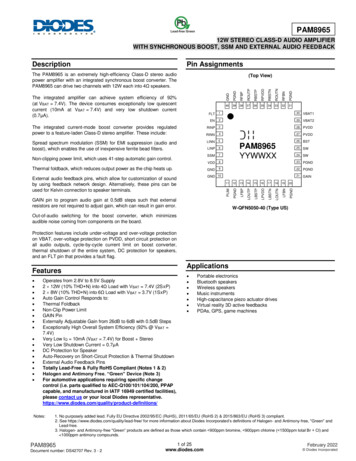
TRANSISTOR AUDIO AMPLIFIER MANUAL6CHAPTER 1Amplifiers with outputs of up to 10 mW.The first transistor amplifiers were, of course,in the very low power range and it is in this fieldthat the transistor has scored its greatest victorybecause valves, at these powers, are hopelesslyThe total current consumption is 21 mA, thecurrent in the output stage being 2 mA with avalves were comparative gluttons for power.With output powers of less than 10 mW it is notnormally possible to obtain satisfactory performance on a loudspeaker although, with a large andsensitive type the output can be surprising. Ampli-A.C. feedback, the loss of gain is very slight.The output stage is not stabilised at all but theinefficient. Even the subminiature hearing aidfiersinthis range will be used mainly withearpieces therefore and are useful in hearing aidsand tiny earpiece radio sets. The quality of reproduction obtained from a good earpiece driven byacarefully designed amplifier can be quitefresh battery.The stabilisation in the first stage is by means ofa feedback resistor. Although this results in someratio of the collector current to the leakage currentis large and any change in the latter will havelittle effect.The earpiece should have an impedance of600 ohms and a D.C. resistance of between 200and 250 ohms. The Fortiphone type T earpieceis suitable.remarkably good and certainly very much betterComponentsWhen the linkage between the diaphragm of theearpiece and the ear drum is air tight the bassResistors -270 ohms, 100K ohms, 3.3K ohms,47K ohms all 1/10th watt.Capacitors -2 microfarad, 3 v.w. x 2. 10 micro -ments of the earpiece are extremely low. TheTransistors-Mullard 0057 and 0058 hearingthan that obtained from a small loudspeaker.response can be excellent and the power require-high sensitivity type of earpiece used with hearingaids requires a peak input of only 1 mW for a goodlistening level and the lower sensitivity types usedfarad 3 v.w. (TSL).Amplifiers for hearing aids and small radiosaid types.Volume Control- 50K ohms log or semi -log.Earpiece -600 to 650 ohms impedance. 200 to 250ohms D.C. (TSL).Battery -1.3 volt mercury cell or 1.5 volt zinccarbon cell.have to operate from extremely small batteries. Ifthe battery of such a unit is to have a reasonablelife the design must be efficient and the earpieceFig. 2. Direct Coupled milliwatt AmplifierAs was shown in Book 1, a considerable savingwith radios require up to about 10 mW depending on the design.must match the output impedance. It is alsoimportant that the amplifier chosen for a particular application be no more than what is requiredas regards output power because the output stageis normally class A and if the amplifier is designedfor a larger output than is required there will bean unnecessary drain on the battery.500 Microwatt output amplifierWhen an earpiece of the type used in hearingaids is employed a really satisfactory sound levelcan be obtained with an A.F. drive power of onlya few hundred microwatts. This amplifier providesan output of mW which is more than sufficientfor people with normal hearing and is even enoughfor many deaf people.The overall power gain of the amplifier is about50 dB or 100,000 times. This makes it quite suitFig. 1.in components can be achieved by the use ofdirect coupling between the transistors. Althoughthis amplifier has one more stage than the lastit uses one less resistor and one less capacitor.The power gain is about 75 dB.The currents of the various stages should beabout 1/3 mA for Tr 1 and Tr2 and about 2 mAfor T3. Because the gains of transistors vary, it isnecessary to adjust the 30K ohm preset. resistorhe correct(which may also be 50 or 100K), .correctcurrent in the output stage. Oncevalue for R has been found it may be replaced bya fixed resistor of the same value.The operation of the circuit depends upon thefact that with these types of transistor high gaincan be obtained at very low levels of collectorvoltage. The collector voltages of Trl and Tr2are in fact the same as the base voltages of Tr2the output stage of a hearing aid.When the amplifier is powered by a mercuryand Tr3. This would normally mean that Tr 1 andTr2 where operated below their knee voltages butby employing very low collector current levels inthe first two stages this is avoided.omitted since no unwanted feedback will occur.The life of this cell in the circuit will be over 100hours despite its small size.higher internal resistance of a zinc -carbon cell islikely to cause motor -boat oscillation.able as the A.F. section of a small radio or forcell such as the RM625, R1 and Cl may beThe battery must be a mercury cell since the
TRANSISTOR AUDIO AMPLIFIER MANUAL7RI270 fl-1.3 or .4F2p.OC 581)1 OC 57Input50 KII 2 1.1,CI10p.Fig.I.500p,W.outputamplifier.TSLIK33 KTr. Magneticearpiece.Tr 3Tr. 2IOC 59impedance2.7K04. 57OC 58- 1.3 V.I2p,10 j.-Fig.2.Directcoupled1/2 mW.amplifier.
8TRANSISTOR AUDIO AMPLIFIER MANUALBecause of the particularly stringent requirements on the transistors, the use of types otherthan those specified may lead to trouble such asdistortion or no signal at all. 0070's and 0071'smay work depending upon the parameters of theindividual transistors.ComponentsResistors -3.3K ohm, 2.7K ohm, 5.6K ohm,1/10 watt or more.Capacitors -2 microfarads and 10 microfarads.1.5 v.w. or more (TSL).Preset Resistor -30K, 50K or 100K ohms.Transistors-Mullard 0057, 0058 or 0059.Earpiece -500 to 1,000 ohms impedance D.C.resistance not more than 350 ohms (TSL).Fig. 3.A 2 mW directly coupled amplifierThis circuit is similar to the last one but isdesigned for an output power of around 2 mW.Fig. 4. 5 Milliwatt AmplifierThe amplifier of fig. 4 is suitable for either anearpiece or to give low volume on a loudspeaker.It may be used in a powerful hearing aid or fora pocket radio. In the latter case, the set couldbe designed to drive an earpiece normally and toplug into a matching transformer and loudspeakerfor use at home. If the speaker is a large sensitive one the volume will be quite sufficient fora quiet room. The transformer used should havea turns ratio of 6 1 for a 3 ohm speaker and of4 : 1 for a 10 ohm speaker. The primary of thetransformer is, of course, connected in place ofthe earpiece. If a sensitive high impedance loudspeaker is available this may be connected directly:in place of the earpiece but there will be someloss of output power because the D.C. resistanceof the speaker will be higher than that of the ear-piece it replaces.The first stage is stabilised by the emitterIt also differs in the method of stabilisation whichemploys an emitter resistor and a base potentiometer as in conventional circuits. Unlike conventional circuits, however, the biasing is appliedresistor and base potentiometer method tois perfectly satisfactory but results in rather a largeloss of power across the 150 ohm resistor. A losswhich is not present in circuits of the type shownin fig. 2. It also necessitates the use of a largevalue electrolytic capacitor, in this case 80 micro farads, which tends to be a rather bulkycomponent.5.6K ohms.The overall power gain of the amplifier is aboutto all three stages simultaneously. This methodacollector current of around 600 microamps. Theoutput stage is not stabilised and R must beselected to provide a collector current of around10 mA. This normally means a value of about45 dB and if it is to be used in a hearing aid twostages of pre -amplification "1 be required. For aradio set or gramophone, .ar, it should havesufficient gain as it stands tor normal use.As with the last circuit, transistors of normaltype such as the 0C71,may work but may not beComponentsThe amplifier may be used as a hearing aid byconnecting a microphone between the input ter-Capacitors -2 microfarad, 8 microfarad and 2satisfactory.minals. A magnetic type shouldbeused,preferably with an impedance between 500 and1,000 ohms. When used as the A.F. section of apocket radio the gain is likely to be more thansufficient and a volume control on the input will,almost certainly, be required.10ohms, 2.2K ohms,1K ohm, 150 ohms. 1/10 watt.Capacitors -2 microfarads and 80 microfarads,1.5 v.w. or -more (TSL).Transistors-Mullard 0057, 0059, 0058 oneeach.Earpiece-About 250 ohms impedance, 55 ohmsD.C. (TSL).Battery -1.3v. Mallory mercury cell such asRM625.Mercury cells are available normally fromchemists as they are used in hearing aids. One ofthe tiniest types, the RM400, is hardly larger thanan aspirin tablet and yet it will give a life of 20hours in this circuit and of about 40 hours in theprevious one.microfarad 1.5 v.w. (TSL).Transistors-G.E.C. types GET114 two off.Earpiece -100 to 120 ohms impedance, 30 to 50ohms D.C. (TSL).Fig. 5.Direct coupled amplifier with low batterydrain.By combining N.P.N. and P.N.P. transistorsComponentsResistors -15K ohms,Resistors -22K ohms, 1.8K ohms x 2, 220 ohms,for value of R see text.in a circuitsome interesting results can beobtained. N.P.N. transistors are only just becoming available in Great Britain but their use incomplementary symmetry circuits makes it likelythat many types will soon be on the market at thesame sort of price as their P.N.P. equivalents.In this amplifier the output transistor is directlycoupled to the driver with the volume control acting as the load for the former. When the settingof the volume control is reduced the base bias ofTr2 is reduced by a proportionate amount and thiscauses the collector current to drop. Thus, whenthe volume required is less than the maximum ofwhich the amplifier is capable, the collector current of Tr2 is below its maximum value and thedrain on the battery is reduced. The only disadvantage with this system is that the signal
TRANSISTOR AUDIO AMPLIFIER MANUAL9T SL2.2 K25052IKimpedanceMagneticearpiece.-r15 KOC 59OC 57OC 58- 1.3V.10 KAppro.15011Fig.A3.80 p.2 mW.directlycoupledT SL1.8K22 Kamplifier.see text.41 12012impedanceMagneticearpieceGET 114IGET 11414.2p.2 p,18 K220.1Fig.4.5 mW.amplifier.1.5V.
TRANSISTOR AUDIO AMPLIFIER Tr. 2IOC 71OC 139IKR-1see tery-6 V.fl I10KTSLto 2KimpedanceMagneticearpiece.OC 71OC 71IS K2501120 j.Fig.6.6 mW.direct-coupledamplifier.
TRANSISTOR AUDIO AMPLIFIER MANUALfeeding the amplifier must not be more than isrequired to fully drive the output since this wouldresult in a distorted output whatever the settingof the volume control. This type of amplifier isbest suited therefore, for use in a radio with goodA.G.C. or a hearing aid with A.V.C.SomeAmerican radios already use the principle. Thevalue of R should be chosen to provide a collectorcurrent of about 10 mA in the output stage withthe volume control in its maximum position. Thiswill normally mean that R is around 330K ohms.Since both transistors are operated in the common emitter mode the overall power gain of theamplifier is high being at least 45 dB. Since theoutput power is also high a low sensitivity earpiece, such as those designed for use with radios,will be satisfactory.ComponentsResistors-R (see text), 1K ohm, volume control.22 ohm 1/10 watt.Capacitor -2 microfarads 3 v.w. (TSL).Transistors-Mullard 0C139 and 0071.Earpiece -250 ohms impedance. Higher valuesmay be used (TSL).6 Milliwatt direct - coupled amplifierWhere a rather higher battery voltage than wehave been considering is available this type ofcircuit is useful. The higher voltage is necessarybecause the transistors are in series across theFig. 6.power supply.The method of stabilisation used was describedin Book 1. The base bias for Tr 1 is taken fromthe emitter of Tr2 and the latter obtains its basebias from the collector of Tr 1. The stabilisation isexcellent and the gain is high.The output is sufficient to drive a sensitiveloudspeaker via an output transformer. The transformer should have a turns ratio of about 20 : 1for a 3 ohm speaker and about 10:1 for a 10ohm type.11Fig. 7. Complementary Symmetry Push -PullAmplifierFig. 7 shows another use of N.P.N. and P.N.P.transistors in a single circuit. This type of appli-cation is even more useful although, unfortunately,suitable transistors are not yet readily available.Trl is a conventional common emitter amplifierwith an A.F. choke as the load. Tr2 and Tr3 fora transformerless push-pull output stage which,because the operation is class B, is extremelyefficient and gives a good output with a very lowbattery drain. The output transistors are operatedthe common collector mode which makesaccurate matching, which is very hard with ainP.N.P./N.P.N. pair, unnecessary. Common collector operation also reduces cross -over distortion very considerably making it possible to relyentirely on the leakage current of the transistors.As the circuit stands, the output power is onlyabout 1/3 mW. This may be increased, however,merely by reducing the value of the load whichinvolves, in this case, reducing the impedance ofthe earpiece. With a 1K ohm impedance earpiece(TSL) the output power will be mW with a freshbattery and the output with 500 ohm and 250 ohmearpieceswill be 11 and 3 mW respectively.Reducing the value of the earpiece will reduce thegain slightly.The advantages of common collector operationfor the output stages have been mentioned. Thereis one disadvantage, however, the drive voltagerequired is very much higher whilst the currentdrive remains the same. In this case the necessarydrive voltage has been achieved by using a chokeas the load for Tr 1. This makes the output impedance of this stage much the same as that of theoutput stage. With choke coupling and commoncollector operation in the output stage, the samedegree of gain is achieved as would be obtainedwith R -C coupling and a common emitter output.The quality, however, is far better than could everbe obtained with the latter.A nine volt battery may be used without causany trouble and this will increase themaximum output power considerably. None ofthe other components need be changed. ExtremelyCapacitors -2 x 2 microfarads and 10 micro -small 9 volt batteries, such as the Ever Ready PP5,are now available and, together with this amplifierTransistors-Tr 1-0071 or similar. Tr2- 0071ingand a suitable tuner circuit, they make possibleextremely small radios.ComponentsResistors -10K ohms, 15K ohms, 250 ohms. 1/10watt or more.Capacitors -2 microfarad 6 v.w. 20 microfarad3 v.w. (TSL).Transistors -2 Mullard 0071's or similar.Earpiece -1 - 2K ohms impedance. Low sensitivity type may be used (TSL).ComponentsResistors -10K ohms, 4.7K ohms, 2.2K ohms.farads 3 v.w. (TSL).or similar. Tr3-0C139 or similar.Earpiece-See text.Fig. 8. 1.5 Milliwatt Amplifier for use with acrystal earpieceAll the amplifiers so far described were designedfor use with magnetic earpieces. Crystal earpieceswill not work satisfactorily in these circuits unlessconnected in parallel with a choke and even thenthe results may not be good. These earpieces are,however, extremely cheap and yet very sensitive
12TRANSISTOR AUDIO AMPLIFIER MANUAL400f1 .4.7 KOC 71OC 71-I1TSL10K30y,2.2 KI05601KCrystalearpiece.330SI0 005p.Fig.8.12 mW.amplifierforusewithacrystalearpiece.
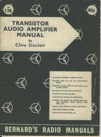
TRANSISTOR AUDIO AMPLIFIER MANUALThe reason for their failure to work in a conventional circuit is two fold. Firstly, the impedanceof this type is normally around 150K ohms andsecondly, they do not conduct electricity.This circuit is specifically designed to overcomethese difficulties and to make the best possibleuse of the earpiece. The first stage is a conventional common emitter amplifier stabilised bymeans of an emitter resistor and a base bias poten-tiometer and transformer coupled to the outputThe output stage is biased in the sameway. The output impedance of the second stageis about 20K ohms and a step up tapped choke isused to match this to the higher impedance ofthe earpiece. An ordinary interstage transformerwith a turns ratio of about 4.5 : 1 may be usedstage.13as the choke. One end of the primary (high impe-dance winding) should be connected to the endof the secondary (low impedance winding). Thefree end of the secondary should then go to batterynegative and the free end of the primary to theearpiece, the join going to the collector. The connection between the secondary and primary of thetransformer must be the right way round but thebest way can easily be found by trial and error.The 10K ohm resistor and the 0.005 microfaradin parallel with the earpiece provide correctionfor the non-linear response of the latter.Although the maximum output of the amplifieris only 11 mW this is quite sufficient to drive theearpiece to full volume.CHAPTER 2Amplifiers with outputs between 10 and 100 mWAll requirements for an amplifier to drive anearpiece should be met by one or other of thecircuits given in the last chapter. In some casesthe amplifier may be suitable apart from the battery voltage used or the amount of gain provided.The former may be changed to suit requirementsif the principles outlined in Book 1 are followed.The latter problem may be overcome by removalor addition of a stage of preamplification as thecase requires.No earpiece requires a driving power of morethan 10 mW so all the amplifiers in this chapterare designed to drive a loudspeaker although, ofcourse, they may be used with an earpiece as anauxiliary. The range of output powers discussedhere covers that provided in a great many of thecheaper types of pocket and " toy " radios as wellas a smaller number of portable gramophones andtape recorders. With a sensitive loudspeaker anda carefully designed enclosure or case, a reasonable amount of sound can be obtained with thisorder of output power but there is bound to be acertain amount of distortion on peak (clipping) unless the average volume is very low. With a smallradio this will not matter much because the qualityis not very good anyway making these sets bestsuited to speech or light background music whereclipping will not be objectionable.Low powered pocket sets may use either asingle transistor class A output stage or two tran-sistors in class B push-pull. The latter are notvery common in this power range and, since thecircuits used are identical to those given in the nextchapter but with a lower voltage or higher turnsratios in the transformers, none are included here.Class A output stages are more common becauseat this level of consumption from the battery thegreater efficiency of the class B output is lesssignificant than the economy of the class A output.Fig. 9. 20 mW Class A AmplifierThis amplifier is typical of those to be foundin a great many cheap portables, particularlythose of Japanese origin. A great many of thesesold under the title of " Boys' Radio " or " ToyRadio " to satisfy the requirements of the Japanese government, are two transistor reflex receiversin which the output stage will be similar to fig. 9and the first transistor will be both a regenerativeR.F. amplifier and an audio driver.The circuit of the amplifier is completely con-ventional and extremely stable. Virtually anysmall signal A.F. transistors may be used withoutany significant change in performance other thanoverall gain. Tr 1 is a common emitter amplifieroperating with a collector current of 1 mA thislevel being chosen for maximum gain the driverequirements of the output stage being extremelysmall. Biasing is by means of an emitter resistorand a base potentiometer which provide quiteadequate stability for all normal conditions. Theemitter bypass capacitor has a value of 32 micro farads which is sufficiently large to provide a bassresponse which is more than good enough for allradio requirements. The collector resistor couldbe made slightly larger without clipping occurringbut since the input impedance of the next stage isvery low any increase in gain achieved in this waywould be negligible.The output stage is biased in the same way asTr2 and also acts as a common emitter amplifier.The quiescent collector current is only 11 mA andthis is no more than can be drawn from even thesmallest battery on the market. With the outputpower available the loudspeaker should be as sensitive as possible. Even a very small type can givegood results at this level. For example, the TSLLorenz LP45F which has an overall diameter ofonly 11", works very well indeed. With a 10 ohms
14TRANSISTOR AUDIO AMPLIFIER MANUAL-6 V12:12.2K5.6K22 K3nTSLLP 316p,6p,ITr. 2GET 114GET 114Tr.I1.8 K1470-ClFig.947047class-A20 mW.100p,n32p,amplifier.IK-9 V.17:1aaaaaaaaeon 50y,5.6 KAMMO.AM 3nTSLLP 31Tr. 2OC 7222 K4.7loon100KJLFig.10.Directcoupled30 mW.amplifier.
TRANSISTOR AUDIO AMPLIFIER MANUALspeaker the turns ratio of the output transformershould be about 6.5 : 1.Fig. 10. Direct Coupled 30 mW AmplifierBy using direct coupling techniques an ampli-fier of comparable performance to that of fig. 9but using far fewer components can be built.Ignoring the battery decoupling components whichwere not included in the last circuit, fig. 10 onlyuses 4 resistors and 2 essential capacitors compared with the 7 resistors and 4 capacitors used in9. This is useful not only because it savesexpense but also because the amount of spaceavailable is normally very limited in miniaturefig.radios, tape recorders and gramophones.The circuit of fig. 10 was designed by Perdioand used by them in one of their first radios. Thethermal stability is good and quite wide tolerancesin the components may be accepted without lossof performance. The only disadvantage with thistype of circuit is that the collector voltage of Trlis about the same as the emitter voltage of Tr2.Here there has to be a compromise because theemitter voltage of Tr2 should be as low as possibleto avoid loss of power and this makes the collector -emitter voltageofTr 1lower than isdesirable. In practice, any loss of power gainresulting from this compromise is made up for bythe fact that there is less loss in the couplingbetween the transistors than there is in conventional circuits.The 0.04 microfarad capacitor compensates forthe fact that small output transformers and smallloudspeakers are more efficient at the high frequencies than they are at the low frequencies. Ifa large transformer and speaker are used this com-ponent may be omitted oritsvalue may bereduced.The input sensitivity of the amplifier for anoutput of 50 mW is 20 mV. Since the inputimpedance is 1K ohm this makes the overall powergain just over 50 dB or 100,000 times. This ismore than adequate for use with an ordinarysuperhet front end.The collector currents of Tr 1 and Tr2 are 0.5and 20 mA respectively. The total battery drainis 22 mA which is still well within the scope ofbatteries using cells as small as those used in slimpenlight torches. The consumption would not haveto be a great deal higher, however, to make theuse of a small battery unsatisfactory. This is whysmall pocket sets with output powers above about50 mW almost invariably use push-pull outputcircuits. An additional reason is that in aclass A circuit there is a continuous flow of directcurrent through the primary of the output transformer which degrades the performance and makesa larger transformer than is used with a push-pullcircuit necessary. With current levels much above25 mA the transformer will be too large for areally tiny pocket set.ComponentsResistors-R1-1.8K, R2 -5.6K, R3-470 ohms,R4 -1K, R5 -3.3K, R6 -4.7K, R7-47 ohms.Capacitors-C1-10 mfd, C2-100 mid, C3-10mfd, C4-10 mfd (TSL).T1-Turns ratio 3 : 1, primary inductance equalto or greater than 4H, maximum primaryresistance 500 ohms.T2-Turns ratio 10 1, primary inductance equalto or greater than 1H, maximum primary:resistance 20 ohms.Fig. 12.Simple 60 mW Gramophone AmplifierThe more sensitive ty
In Book 1 of " Practical Transistor Audio Amplifiers " I dealt with the basic principles involved in transistor A.F. amplifier design and the practical examples given were mainly limited to single stages. In this second book the situation is reversed and all the space is devoted to practical amplifier circuits employing all the principles and