Transcription
Table of ContentsPrologue Back to the Future3Chapter 1 An Introduction to SysML and EnterpriseArchitect Engineering Edition4Chapter 2 Audio Player Requirements14Chapter 3 Audio Player Behavior18Chapter 4 Audio Player Structure27Chapter 5 Audio Player Constraints and Parametrics32Chapter 6 Audio Player Hardware Implementation39Chapter 7 Audio Player Software Implementation54Copyright 2010 Sparx Systems Pty Ltd and ICONIX. All rights reserved. All trademarkscontained herein are the property of their respective owners. The OMG SysML logo is atrademark of the Object Management Group, Inc.
Prologue - Back to the FutureThis book represents a departure from what I’ve been doing at ICONIX over the last 25years, which has been focused mainly on Software Engineering, but a book on how todevelop real-time embedded systems is actually a “return to my roots” in ElectricalEngineering.My degree is actually in EE, not Computer Science, and my path to being involved withSoftware Engineering had its formative years when I was working as a programmer inComputer Aided Design for VLSI in the aerospace industry in southern California, and alsoup in Silicon Valley. So even though SysML is a new area for me, I’m inherently familiar withthe problems that SysML helps to solve.My first four jobs out of college (in the early 1980s) were involved with VLSI design. Three ofthese (two at TRW and one at Hughes Research Labs) were on a project called VHSIC (VeryHigh Speed Integrated Circuits), which is what the “V” in VHDL stands for. At TRW my workinvolved extending some of the early “design rule checking” software to cover a morecomplex fabrication process that allowed us to deliver gigahertz-level speeds, which wasmuch more of an accomplishment 30 years ago than it is today. I also worked a bit withSPICE, one of the earliest “circuit simulators” (more about simulation in the “SysMLparametrics” discussion in Chapter 5).Later, after a short stint up in Silicon Valley working on something called “symbolic layout andcompaction” at a company called Calma, I returned to TRW where I designed andprogrammed an application called “Hierarchical Layout Verification” which recursivelydecomposed a complete integrated circuit layout into sub-cells (now called “blocks” inSysML), determined their input and output “ports” (another familiar SysML concept), andchecked both physical design rules and electrical connectivity.During this time, my boss Jim Peterson at TRW was developing one of the early HardwareDescription Languages, which he called THDL (for TRW Hardware Description Language).1THDL itself was an extension of CIF (Caltech Intermediate Format ) which had beendeveloped in Carver Mead’s research group when Jim was a grad student at Caltech. SinceJim’s THDL work was funded under the VHSIC contract it’s a safe bet that some of theconcepts in VHDL had their roots in THDL.After my second go-round at TRW, I went to work at Hughes Research Labs in Malibu, CA,developing the interface from CAD systems (most notably Calma, who owned about 80% ofthe market back then) to something called the VHSIC Electron Beam Lithography System.This was another ambitious project that pushed the state of the art in fabrication technologyfar ahead of what it had been previously. We were writing one-tenth-of-a-micron lines onsilicon wafers using electron beams (still not bad today) back in 1984.When Sparx Systems asked me to write this eBook, I discovered a kindred spirit in SamMancarella, who is largely responsible for a great deal of the implementation of EnterpriseArchitect’s SysML solution. Sam also developed the Audio Player example that this book iswritten around, which is such a complete and comprehensive example that it made my writingtask very easy. I want to make it completely clear that Sam deserves ALL of the credit fordeveloping this example, and that my contribution to this project was simply writing themanuscript around the example. My electrical engineering background made it obvious to mehow good Sam’s example is, and allowed me to see how the pieces fit together.1Introduction to VHDL By R.D.M. Hunter, T.T. Johnson, p.17-18
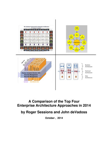
Chapter 1 - An Introduction to SysML andEnterprise Architect Engineering EditionA roadmap for embedded system developmentIt’s easy for a book to present a taxonomy of disjointed SysML diagrams and then leave youto figure out how to combine those diagrams into a meaningful model. In fact, that’s what themajority of SysML books that we’ve seen appear to do. But with this book, we’re going tointroduce you to SysML and the Systems Engineering Edition of Enterprise Architect in arather different way.At ICONIX, we’ve had pretty good success when we defined an unambiguous developmentprocess, and presented that development process in “roadmap” form. We’ve developedprocess roadmaps for use case driven software development, business modeling, designdriven testing, and algorithm-intensive software design. In this book we’re going to do itagain, this time for embedded systems that involve a combination of hardware and software.We’ll explain the roadmap at the high level in this chapter, and then each of the followingchapters will detail one of the high-level activities on the top-level roadmap. Along the way,we’ll show you how Enterprise Architect’s System Engineering Edition supports the processwe’re describing, while illustrating each step of the process by example.In addition to providing complete support for all SysML 1.1 diagrams, the Enterprise ArchitectSystems Engineering edition combines advanced features such as executable codegeneration from UML models (including support for hardware languages such as Verilog andVHDL), executable SysML Parametric diagrams and advanced scripting. We’ll explore thisunique combination of advanced capabilities in the last half of this book.Specifically, In Chapter 5 we’ll explore Enterprise Architect’s SysML Simulation Support, whichprovides the capability of simulating SysML 1.1 constraint models with resultsgraphing capabilities; In Chapter 6 we’ll describe support for Hardware Description Languages, includingVerilog, VHDL and SystemC, with support for generating State Machine code; and In Chapter 7 we’ll illustrate Enterprise Architect’s support for generating functionalsource code for State Machines, Interactions and Activities in C, C , C#, Java andVBNet .Each of these capabilities, taken standalone, adds a significant amount of “horsepower” for asystems engineering effort. We’ll show you how to combine these capabilities into a singleprocess roadmap that’s greater than the sum of its parts.Figure 1 shows the top level roadmap for ICONIX Process for Embedded Systems.
act RoadmapSystemConceptDefine SystemRequirementsModel System BlockStructureModel System Behav iorDefine Constraints andParametricsSimulateImplement Hardw areImplement Softw areTest Hardw are andSoftw areDeliver SystemFigure 1 – ICONIX Process Roadmap for Embedded Systems DevelopmentAs you can see, our roadmap starts off by defining requirements, proceeds through modelingof system behavior and block structure, and then through definition of constraints andparametrics, simulation, and then implementation in both hardware and software. We’ll takeyou through each of these activities at a summary level in this chapter, and then in moredetail, illustrated by a comprehensive Audio Player example, in Chapters 2-7.
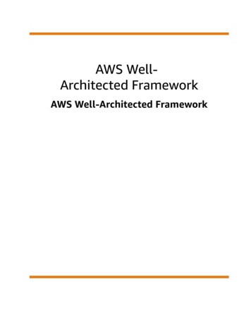
Requirements, Structure, Behavior, and Parametrics – theFour Pillars of SysMLOur Embedded Systems Development Process Roadmap is organized around producing aSysML model that is generally organized into four sections. These parts of the overall systemmodel (Requirements, Structure, Behavior, and Parametrics) are sometimes referred to as“The Four Pillars of SysML”. 2act Define System RequirementsDefine FunctionalRequirementsDefine Non-FunctionalRequirementsOrganize Requirementsinto HierarchiesAllocate Requirements toSystem ElementsFigure 2 – Roadmap: Define System RequirementsRequirementsRequirements are generally categorized as Functional Requirements, which representcapabilities of a system, and Non-Functional Requirements, which cover such areas asPerformance and Reliability. You can organize Requirements into hierarchies on requirementdiagrams. Enterprise Architect supports allocation of requirements to other elements using asimple drag-and-drop, and automatic generation of traceability matrices.Figure 2 shows the steps for Requirements definition from our process roadmap. Note thatallocation of Requirements to System Elements is really an ongoing process as the model isdeveloped, and largely occurs within other roadmap activities. We’ll explore RequirementsDefinition in more detail in Chapter 2.2OMG Systems Modeling Language Tutorial, INCOSE 2008
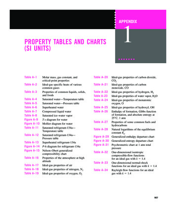
Structureact Model System Block StructureStart Modeling StructureModel the ProblemDomainDefine BlocksAllocate Requirementsto BlocksDefine PortsActivityFinalFigure 3 – Roadmap: Model System Block StructureBlocks can be used to represent hardware, software, or just about anything else. Blockdefinition diagrams represent system structure. Internal block diagrams describe the internalsof a block such as parts, ports, and connectors. As with UML, Packages are used to organizethe model.If you think of a Block as an electronic circuit (one of many things that a Block can describe),the Ports define the input and output signals to/from the circuit. SysML allows you to describethe input signals and transformations in great detail, and Enterprise Architect contains a builtin simulator that allows you to plot the output graphically or export to a comma-separatedvalue file. You’ll see how this works in detail in Chapter 5. Defining the Block structure is aprerequisite for defining parametrics and running simulations.Here’s how our process roadmap approaches defining system structure. See Chapter 3 foran expanded discussion on modeling structure.
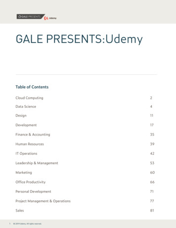
Behavioract Model System Behav iorStart Behavior ModelingModel Use CasesModel Finite StateBehav iorAllocate Requirements toUse CasesAllocate Requirements toState MachinesModel Interactions for UseCasesComplete Behaior ModelingFigure 4 – Roadmap: Model System BehaviorSysML provides four main constructs to represent different aspects of system behavior; usecases, activity diagrams, sequence diagrams, and state machines.Our roadmap shows two parallel branches for modeling system behavior. One branch startswith use cases 3 , which describe scenarios of how users will interact with the system. Usecases generally consist of a “sunny-day” part which describes a typical success-path for thescenario, and multiple “rainy-day” parts which describe unusual conditions, exceptions,failures, etc. Use cases are typically detailed on Interaction (Sequence) Diagrams.The other branch on the roadmap involves defining event-driven, finite-state behavior ofsome part of a system using state machines. As a simple example, there is finite statebehavior associated with the power charging circuitry on our Audio Player. One of EnterpriseArchitect’s unique capabilities is the ability to generate functional (algorithmic) code fromstate machines. As you’ll see, these state machines can be realized in software or inhardware using Hardware Description Languages (HDLs).Requirements are allocated to both use cases and states. Chapter 4 explores behaviormodeling in detail.3See “Use Case Driven Object Modeling with UML: Theory and Practice” by DougRosenberg and Matt Stephens for a lot more information about use cases.
Advanced Features of the Enterprise Architect SystemEngineering Editionact Define Constraints and ParametricsStart defining constraints and parametricsDefine Constraint BlocksAdd Scripts to ConstraintBlocksDefine ParametricDiagramsSimulate Parametric ModelsFigure 5 – Roadmap: Define Constraints and ParametricsEnterprise Architect Systems Engineering edition contains a number of unique features forsystems and software engineers working on embedded systems. The Systems Engineeringedition combines new features such as executable SysML Parametric diagrams andadvanced scripting with executable code generation from UML models (including support forhardware languages such as Verilog and VHDL, and bundles licenses for DoDAF-MODAF,SysML, DDS and IDE integration products to provide powerful model-driven constructiontools to tightly bind your code development in Eclipse or Visual Studio with the UML/SysML.Our process roadmap leverages these unique capabilities into a synergistic developmentprocess.
Parametricsact SimulateDefine Constraints and ParametricsConfigure SimulationAssign Inputs toParametersAssign Values to InputParametersSpecify Output ValueClassesSpecify ReportingOptionsRun the SimulationFigure 6 – Roadmap: SimulateParametrics allow us to define detailed characteristics, physical laws, and constraints onsystem blocks that allow us to simulate how a system will behave, then make engineeringtradeoffs, and re-simulate until our design meets the specified requirements.Our roadmap provides two high-level activities in this area; the first to define constraint blocksand parametric diagrams, and the second to configure and execute the simulations.The ability to configure and execute simulations within Enterprise Architect, eliminating theneed to export the model to external simulation software, is one of the unique capabilities ofthe Sparx Systems SysML solution.Enterprise Architect’s built-in support for scripting and graphical display of simulation resultstightens the feedback loop on making engineering tradeoffs in the model to rapidly ensurethat all system requirements are met. You’ll see how this works in detail in Chapter 5.Implement HardwareHardware Description Languages allow the specification of electronic circuits in a software-
like representation. According to Wikipedia 4 :In electronics, a hardware description language or HDL is any language from aclass of computer languages and/or programming languages for formal descriptionof electronic circuits, and more specifically, digital logic. It can describe the circuit'soperation, its design and organization, and tests to verify its operation by means ofsimulation.HDLs are standard text-based expressions of the spatial and temporal structureand behaviour of electronic systems. Like concurrent programming languages, HDLsyntax and semantics includes explicit notations for expressing concurrency.However, in contrast to most software programming languages, HDLs also includean explicit notion of time, which is a primary attribute of hardware. Languageswhose only characteristic is to express circuit connectivity between a hierarchy ofblocks are properly classified as netlist languages used on electric computer-aideddesign (CAD).HDLs are used to write executable specifications of some piece of hardware. Asimulation program, designed to implement the underlying semantics of thelanguage statements, coupled with simulating the progress of time, provides thehardware designer with the ability to model a piece of hardware before it is createdphysically. It is this executability that gives HDLs the illusion of being programminglanguages. Simulators capable of supporting discrete-event (digital) andcontinuous-time (analog) modeling exist, and HDLs targeted for each are available.act Implement Hardw areGenerate State MachinesGenerate VHDLGenerate VerilogGenerate System CFigure 7 – Roadmap: Implement HardwareEnterprise Architect’s long-proven ability to generate code has been extended to supportcode generation in VHDL, Verilog, and SystemC in the Systems Engineering Edition. Whilecode generation is independent of SysML usage, from a process roadmap standpoint, thismeans we can drive both hardware and software implementation from our SysML model.Once code is generated in an HDL, it’s possible to “compile to silicon” to realize the hardwaresolution on a chip.We’ll explore hardware implementation in Chapter 6.4http://en.wikipedia.org/wiki/Hardware description languages
Implement SoftwareSoftware implementations can leverage a variety of powerful capabilities that are includedwith the System Engineering Edition of Enterprise Architect. Two of the more important andunique capabilities are: The ability to generate functional (algorithmic) code from behavioral models (statemachines, activity diagrams, and interaction diagrams) The ability to integrate Enterprise Architect models into development environmentssuch as Eclipse and Visual Studio.Figure 8 shows a high-level look at the Software Implementation activity from the roadmap.act Implement Softw areGenerate Functional Codefrom Activ ity DiagramsBuild in Visual Studiousing MDG IntegrationGenerate Functional Codefrom State MachinesBuild in Eclipse usingMDG IntegrationFigure 8 – Implement SoftwareWe’ll explore these unique capabilities and how they work together in Chapter 7.
Introducing the Audio Player ExampleOver the course of this book, we’ll be illustrating the steps in our process by presentingdiagrams from an example project. Our example (developed by Sam Mancarella) will be ahardware/software system that most everyone is familiar with – an Audio Player.The top level Package Diagram in Figure 9 shows how the example model is organized.pkg Requirements ModelRequirements ModelThis package contains the models that define therequirements of the Portable Audio Player. The modelcontains requirement specifications, use cases,interactions, state machines and constraint blocks.Specifications Durability Media AccessUse Cases Top Level Maintain Audio Player Performance Maintain Playlist User Friendliness Operate Audio PlayerSpecificationsConstraint Blocks EchoDSPUse CasesInteractionsState Machines Operate Audio Player Maintain Playlist Maintain Audio Player deviceInContext listenerConstraint Blocks DSP Effects Operating States Playlist MaintenanceState MachinesInteractionsFigure 9 – SysML models are organized into Requirements, Behavior, Structure, Constraints andParametrics, and include both Hardware and Software Implementation models.You’ll become intimately familiar with Sam’s audio player example, as we’ll be using it toillustrate the various activities on our roadmap throughout the following chapters.
Chapter 2 – Audio Player RequirementsRequirements RoadmapRequirements are the foundation of a SysML model. The purpose of the system that you’remodeling is to satisfy the requirements. So, as you’d expect, the roadmap begins withdefining requirements (see Figure 1).act Define System RequirementsDefine FunctionalRequirementsDefine Non-FunctionalRequirementsOrganize Requirementsinto HierarchiesAllocate Requirements toSystem ElementsFigure 1 – Requirements Definition RoadmapAs you saw in Chapter 1, Requirements are usually classified as Functional (e.g.Requirements that represent specific system features or capabilities), and Non-Functional(e.g. Requirements that don’t apply to specific features such as ease-of-use). It’s importantto organize these Requirements effectively, otherwise the Requirements model can becomeDysfunctional 5 .When you think about Requirements in a SysML model, you’re considering HardwareRequirements, Software Requirements, and Requirements that relate to the Environment thatyour system will interact with. For example, our Audio Player will interact with its operatingenvironment, which includes “listening conditions” (noise, weather), and the clothing of thelistener.5For more on avoiding Dysfunctional Requirements, see Use Case Driven Object Modelingwith UML – Theory and Practice, by Doug Rosenberg and Matt Stephens.
These domain aspects drive downstream requirements which describe items such as shockresistance, waterproofing etc., because we expect the audio player to operate within thelisteningDomain defined by this internal block diagram (ibd) which describes thelisteningConditions to which the player will be subjected.The ‘blocks’ shown in Figure 2 will be decomposed into their parts to describe this domain‘system’.ibd dioPlayerexternalNoisew eatherlisteningConditionsversion "1.0"description "Concept to identify top level domain entities"completeness "partial. Does not include some externalinterfaces"Figure 2 – SysML Models include Hardware, Software, and the Environment within which a system mustoperate.Modeling Tip – It’s easy to import graphics into EnterpriseArchitect ModelsAs you can see from the example in Figure 2, adding some graphics (photos, illustrations,etc.) to a model can make it far easier to understand. Enterprise Architect makes this easy todo. There are several ways to do this, but one of the easiest is to copy an image to theclipboard, then right-click an element on a diagram, select Appearance from the contextmenu, and then select Apply Image from Clipboard. It only takes a few seconds, but addsa lot to the readability of your model.
Audio Player RequirementsSysML defines seven relationships between Requirements. These fall into two categories:relationships between Requirements, which include containment, derive, and copy; andrelationships between requirements and other model elements, which include satisfy, verify,refine, and trace.The “crosshair” notation in the Audio Player Requirements diagram below shows the use ofcontainment to organize requirements hierarchically into Categories meaning that theSpecifications Package OWNS the requirements, which in turn, own the ‘sub requirements’beneath.req y«requireme.Media Access«requireme.Keys tance«requireme.External ports«requireme.Graphical Userinterface«requireme.Batterylongev uctionFigure 3 – Requirements for our Audio Player are organized into Categories such as User Friendliness,Performance and Durability.Enterprise Architect has a couple of built-in features that make it easy to define whichrequirements are satisfied by which model elements, and to automatically generate arelationship matrix to show these relationships.Figure 4 – Enterprise Architect’s Relationship Matrix makes it easy to see the allocation of Requirements toBlocks
Modeling Tip – allocate requirements to model elementsusing drag-and-dropIt’s trivially easy to specify that a model element (such as a Block or a Use Case) satisfies aRequirement within an Enterprise Architect model. Simply drag the Requirement from theProject Browser on to the element which satisfies it. Enterprise Architect automaticallyestablishes the link within the model.It’s also trivially easy to generate a matrix showing the allocations of Requirements to modelelements using Enterprise Architect’s Relationship Matrix.Figure 5 – Enterprise Architect’s Relationship Matrix makes it easy to see the allocation of Requirements toUse CasesModeling Tip – Use Enterprise Architect’s Relationship Matrixto show which model elements satisfy which RequirementsOnce the allocation relationships have been specified using drag-and-drop, or by using the“Require” tab on the Specification dialog of all Enterprise Architect elements, you cangenerate a cross-reference table of Requirements against any type of model element byselecting Relationship Matrix from the View menu. Simply specify the scope (desiredPackage) of your search using the Source and Target buttons, and the type of elements youwish to cross-reference, and Enterprise Architect does the rest. The Matrix can be exportedto a Comma Separated Value (CSV) file using the Options button.In the upcoming chapters, you’ll see how the Requirements we’ve identified here are satisfiedby various aspects of the Audio Player SysML model.
Chapter 3 – Audio Player BehaviorBehavior Modeling RoadmapBehavior Modeling describes the dynamic behavior of the System as it interacts with usersand with the environment. You’ll use interaction diagrams and use cases to modelinteractions between users and the system, and state machines to describe event-drivenbehavior that’s not user-centric. Figure 1 shows the Roadmap activities.act Model System Behav iorStart Behavior ModelingModel Use CasesModel Finite StateBehav iorAllocate Requirements toUse CasesAllocate Requirements toState MachinesModel Interactions for UseCasesComplete Behaior ModelingFigure 1 – Behavior Modeling RoadmapAs you can see, you approach behavior modeling in two parallel branches, one for use casesand the other for state machines. Each branch includes allocation of Requirements to modelelements (use cases or states). Use cases are described in natural language at the highlevel, and are detailed on interaction (sequence) diagrams.We’ll follow the roadmap through the remainder of this chapter by exploring the dynamicbehavior of our Audio Player example. Then in Chapter 4 we’ll explore the system structurethat supports the desired behavior. We use the terms “static” and “dynamic” to describe thestructural and behavioral parts of the model; structure is static in that it doesn’t change onceit’s defined, while behavior is dynamic – changing based on user actions or external events.
Audio Player Behavior ModelHere we can see the two branches of the dynamic model for our Audio Player. User-centricscenarios, such as Operating the Audio Player, are modeled with use cases, while we canmodel the Operating States of the device with state machines. Note that PlaylistMaintenance has a use case description and is also described using a state machine.Whatever diagrams help to tell the story can be used.pkg Use Casespkg State MachinesUse CasesThis package contains use cases that describe theinteractions between the Portable Audio Player, thelistener and other participants.State MachinesThis package contains state machines that model thePortable Audio Player's various operational states.Operating StatesTop Lev elTop LevelPlaylist MaintenanceMaintain Audio PlayerMaintain Audio PlayerOperating StatesPlaylist MaintenanceDSP EffectsMaintain PlaylistMaintain PlaylistOperate Audio PlayerOperate Audio PlayerDSP EffectsFigure 2 – Behavioral models include Use Cases, Interactions, and State MachinesModeling Tip – Models should tell a storyA model’s primary purpose is to serve as a communication vehicle to promote a sharedunderstanding about the system being modeled between stakeholders, end-users, analysts,designers, software and hardware engineers, and quality assurance personnel. Alwaysoptimize models for readability, and make sure you “tell the story” clearly and unambiguously.Here are the Top Level use cases for the Audio Player. The “eyeglass” icon on the use casebubbles indicate that a child diagram exists, showing more detail about the use case.uc Top Lev elPortableAudioPlayerOperate Audio PlayerListenerMaintain PlaylistMaintain AudioPlayerFigure 3 – Audio Player Top Level Use Cases
Enterprise Architect makes it easy to “drill down” to a child diagram for composite elements.Here’s a child use case diagram for audio player maintenance.uc Maintain Audio PlayerDevice MaintenanceCharge Battery«include»Replace BatteryReplace SkinListenerReplace HeadphonesMaintain Audio Player (Interaction)Figure 4 – Use cases for maintaining the audio player hardware include charging and replacing the battery,and replacing the skin and the headphones.Enterprise Architect supports “diagram references” for hyperlinking one diagram to another.You can see the reference to the interaction diagram (Figure 5) on the diagram above, and alink back to the use case view on that diagram.sd Maintain Audio PlayerMaintain Audio Player - Use Caselistener :ListenerrefdeviceInContext:Portable tyheadphones]refReplaceHeadphonesFigure 5 – The interaction diagram for maintaining the audio player shows 3 alternate courses of action(defective batteries, worn out skin, and faulty headphones) and one normal course (charging the battery).
Here are the use cases for the basic operations of the Audio Player.uc Operate Audio PlayerOperationsOperate Audio Player (Interaction)Pow er On«extend»PlayListen r«include»Adj ust VolumeRecord Audio«include»StopFigure 6 – Audio Player Use Cases for Listening and RecordingAs in the Maintenance use cases, the use case diagram and interaction diagram (Figure 7)are cross-linked using Enterprise Architect diagram references. This diagram shows that theIdle, Play, Pause, and Adjust Volume paths can all be performed in parallel.sd Operate AudioPlayerOperate Audio Player - Use CasedeviceInContext:Portable AudioPlayerlistener :ListenerrefTurnOnDev frefPauseAdj ustVolumeTurnOffDev iceFigure 7 – Audio Player Interaction diagram for Listening/RecordingUse cases describe how a user interacts with the system. In the next section, you’ll see howto describe event-driven behavior using state machines.
Audio Player State ModelFor embedded systems, it’s often advantageous to describe behavior in terms of operatingstates, triggering events and system actions. SysML (identically to UML) uses state charts todescribe these finite state aspects of a system.stm Operating StatesOff[On][Off]stm ure 8 – Audio Player Operating StatesState charts allow nesting of substates on a single diagram. Figure 8 shows the detailedbehavior of the “On” state of the audio player on the same diagram that shows the “On/Off”behavior. To allocate Requirements to states, simply drag the Requirement from theEnterprise Architect Project Browser and drop it onto the state bubble.State machines relate operating
Architect Engineering Edition . 4 . Chapter 2 . Audio Player Requirements . 14 . Chapter 3 . Audio Player Behavior . 18 . Chapter 4 . Audio Player Structure . 27 . Chapter 5 . Audio Player Constraints and Parametrics . 32 . Chapter 6 . Audio Player Hardware Implementation . 39 . Chapter 7 . Audio Player Software .