Transcription
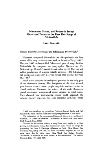
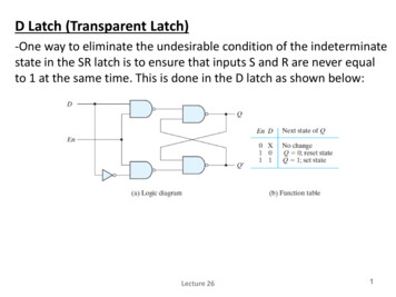
Latch LocksInfo: LL-KL-DKLLatch Locks are used to control and float plates during the mold opening and closing sequence.With three different types, DME provides a range of installation solutions for all applications:1. LL: the original DME latch lock, successfullyused in the field for almost 20 years.A simple, compact design which can bemounted in various configurations on theoutside of the mold.Available in small, medium and large in onestandard length which is easily cut to size by thetoolmaker.2. KL: very sturdy construction available in 6different sizes to handle any mold dimension.Simple machining and adjustment allow easymounting to the outside of the mold.3. DKL: the modern alternative launched in 2004 and hugely popular with mold designers, builders and injectors.Completely contained inside the mold, DKL does not interfere with external cooling lines and no longer preventsmold being placed on its side.Greatly simplifies mold-making as plates no longer need side-machining, only vertical machining. Optional guidedejection saves space in the mold.www.diemouldequipment.com.auTel 1800 224 1351
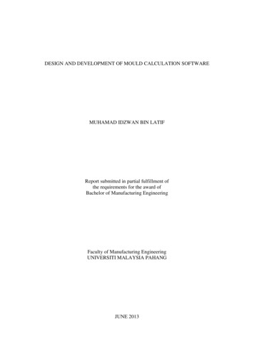
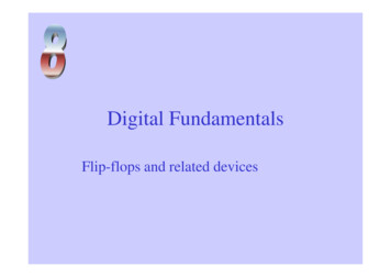
Latch LocksInfo LLMOLD OPENINGPARTING LINEJiffy Latch PLATE“BX”PLATESUPPORTPLATE1ST MOLDOPENING2ND .C.P.1ST MOLDOPENING“A”PLATE2ND MOLDOPENING“B”PLATESUPPORTPLATE1. To control stripper plate.Cycle time is often wasted waiting for the pressknock-out bar to function. With the application ofthe DME Jiffy Latch-Lok, as illustrated to the left,the stripper plate is moved in a secondary actionof the mold opening without the aid of the pressknock-out bar.The Jiffy Latch-Lok permits you to shorten theejection stroke, improve cycle time and increasethe number of parts per shift.2. To float X-plate away from A-plate whilelocking X- and B- plates.In this application of the Jiffy Latch-Lok, the“X-1” plate is floated away from the “A” platein the first mold opening sequence. At apredetermined opening (you determine thedistance) the “X-1” plate is released from the“B” plate for the second mold opening. Thisapplication of the Jiffy Latch-Lok is particularlyeffective on “AX” or three-plate top runnermolds.3. To float A-plate away from top clamping platewhile locking A- and B-plates.In the DME Latch-Lok application illustratedhere, the “A” plate moves away from the topclamp plate in the first mold opening. Duringthis portion of the cycle, the “A” and “B” platesare locked. As the release bar passes the rocker,the “A” and “B” plates part in the second ent.com.au4. Actuation of ejector assembly without aid ofpress knock-out bar.For those mold applications where a shorterpress stroke is required, theDME Jiffy Latch-Lok is extremely effective.You can activate the Jiffy Latch-Lok at anytime after the mold begins to open, and pullthe ejector assembly forward. This simpleaction shortens cycle time and increases partproduction.Tel 1800 224 1352
Latch LocksLLJiffy Latch LockREFW MOLD WIDTHLL 051 ELL 101 ELL 151LL 201W 200200 W 400200 W 400W 400LLBodyABCRocker ØSpringFor 61,9LL 052 E: 22LL 102 E: 32LL 102: 31,2LL 202: 50,2LL 059 ELL 109 ELL 109LL 209LL 051 ELL 101 ELL 151LL 201BodyRocker ØLLLatch barREFLL 053 ELL 103 ELL 153LL 203EFG2For REF1802542544067,911,912,124,816,024,024,837,5LL 051 ELL 101 ELL 151LL 201LLRelease barREFLL 054 ELL 104 ELL 104LL 204MPQFor REF1802542544067,99,99,012,116,024,024,837,5LL 051 ELL 101 ELL 151LL 201LLSpacerREFLL 056 ELL 106 ELL 106LL 206UVWFor 1LL 051 ELL 101 ELL 151LL 201www.diemouldequipment.com.auTel 1800 224 1353
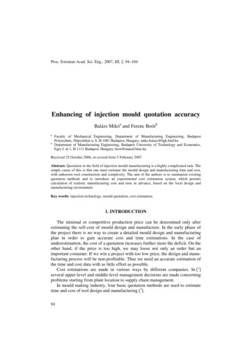
Latch LocksJiffyStarting position of rockeris controlled by a spring ram.Installation instructions LL-051 / LL-101 / LL-201Release bar is ready to disengagerocker from latch bar at end ofrequired ejector stroke if pressovertravelsWith the Latch barX- and B-plates are lockedCut release barto required lengthand dowel it withspacer.SpacerRelease bar1st partingline1st partingline2nd partinglineLatch bar2nd parting line(stripper distance)For one mold at least 2 Latch-loks are required, which are respectively mounted at outer surfaces (center of themold).Body must be parallel screwed and doweled at the molding plate. Latch and release bars must be screwed at 90 tothe parting line (Slotted holes facilitate final adjustment). The bars have to slide properly in the body.Adjustment:Both Latch-loks must be accurately adjusted. Inaccuracies can lead to canting of stripper plates and to breaking ofthe bars.Latch bars and release bars must be preset when the mold is closed. Open mold and check motion sequence ofbars and stripper plate. Fine tuning is necessary. Repeat this procedure until both Latch-loks work together exactly.Then latch bar and release bar can be doweled. Before and during operation apply to all moving parts of the Latchlok C 168 type grease.www.diemouldequipment.com.auTel 1800 224 1354
Latch LocksJiffyInstallation instructions LL-151Release bar is ready to disengagerocker from latch bar at the endof the strokeLatch barParting lineDistance X stopsstroke of ejectorplateStarting positionof rocker iscontrolled byspring ramAmount ofmold openingbeforeejector plate.ReleasebarCut-out slotRelease barCut release bar to required lengthSpacer *release bar and spacer can also bescrewed and doweled togetherWith Latch-lok LL-151 especially the ejector plate is moved, ejector plate (N 50) has to overhang enough, so thatbody and, if necessary spacer* could be mounted. Body and spacer are to be screwed and doweled with N 50.Machine cut-out slot for bars in spacer* and overhanging ejector plates.All other installation instructions as described on LL-051, LL-101 and LL-201.www.diemouldequipment.com.auTel 1800 224 1355
Latch LocksExternal Latch LockPositive and Precise Positioning of Floating PlatesSA(w1)-(L1)HSEx. SA65-200HSSA(w1)PUEx. SA65PUx4x6x3x5x2x1 60 HRC 0.5mm deepSA(w1)LLEx. SA65LLd5w4L3 52 HRC 0.3mm deepd4w3w6 60 HRC 0.5mm deepL9L6L72Stroke 1 0,03L2 0Dl** Performance with delayL9L1item x6L7L9stroke .4250300Tel 1800 224 1352325167-1906w1w2SA(w1)-(Dl)PBEx. SA65-25PB
Latch LocksDME External Latch Lock Allows Precision Control of Mold Plate Latching Operation Ideal for molds with floating plates, including stripper plates& 3-plate molds Floating plates are positively locked in place during moldopening and closing, preventing potential mold damage Ensures floating plates will be where they should be throughout the life of the mold Positively and precisely positions plates every time the moldopens and closes, allowing molds to run faster Simplifies mold design while improving design flexibility Designed and engineered to hold large loads while savingspace inside the mold Simple design reduces machining time & labor costs Standardized components simplify mold maintenance Eliminates springs & associated play in plates, and reduces mold maintenance Standard sizes accommodate most mold base sizes andstroke lengths (4) sizes of housings with (2) housing lengths each; (3)puller bar lengths Puller bars & housing may be shortened as desired Stroke may be with or without delayExample without delayed stroke sequenceExample with delayed stroke sequencew1 (2pcs)INTENDED MOLD SIZETR max. (TRACTION FORCE)LF MAX.(LOCKING FORCE)SzBACKLASH55658095246 x 246396 x 396646 x 646796 x 20.250.250.300.35SA.PU - shock absorber, buffer damperDI - maximum delayed strokeSz - switching zone, stroke 2 begins slightly before the end of stroke 1Animation:Backlash - Segments need clearance/play to allow the locking/unlockingsequence (built into the product)TF - traction force (always retain the lowest)LF - locking force (maximum holding force after stroke -latch-lockwww.diemouldequipment.com.auTel 1800 224 1357
Latch LocksKLLatch locksStaticFmax. 40000 newtonDynamicFmax. 16000 newtonREFKL1-1-70IncludesKFTo be ordered seperatelyKKKVKUNumber of ouldequipment.com.auKL2/2Tel 1800 224 135KU/2/28
Latch LocksKLLatch locksStaticFmax. 40000 newtonDynamicFmax. 16000 newtonREFKL 1-2-90KL 1-2-170KL 1-2-220KL 1-2-270LLaLbl1IncludesTo be ordered .diemouldequipment.com.auTel 1800 224 1359
Latch LocksKLLatch locksStaticFmax. 65000 newtonDynamicFmax. 30000 newtonREFKL 1-3-120KL 1-3-170KL 1-3-220l1l3IncludesTo be ordered seperately120170220182232282WZ8031 B 10-025KUKUKUwww.diemouldequipment.com.auTel 1800 224 13510
Latch LocksKUBaffle barREFKU 1-1-140KU 1-1-204KU 1-1-254Ll1l5 min.l5 max.l6 min.l6 3www.diemouldequipment.com.auTel 1800 224 13511
Latch LocksKUBaffle barBore hole as per customer’s requirementsREFKU 1-2-200KU 1-2-250KU com.auTel 1800 224 13512
Latch LocksKL15Latch locksStaticFmax. 100000 newtonDynamicFmax. 40000 newtonREFKL 2-2-256IncludesKFwww.diemouldequipment.com.auKKTel 1800 224 135To be ordered seperatelyKVKU13
Latch LocksKUBaffle barBore hole as per customer’s requirementsREF for KL 2-2-256KU2-2-400www.diemouldequipment.com.auTel 1800 224 13514
Latch LocksKFSpringsREFPART APART BBL1LKF 12-702x1x2090110KL 1-1-70FOR LATCH LOCKKF 12-902x1x2090110KL 1-2-90KF 12-1702x1x2090110KL 1-2-170KF 12-220-2702x1x20127157KL 1-2-220 - 270KF 22-2562x1x25127157KL 2-2-256KKHeadsREFKK 11-12KK 22AA1A2M37,555DBC23,621157627204026,95157123027KK 11-12 for latch lock KL1-1-70 / KL1-2-170 / KL1-2-220 / KL1-2-270KK 22for latch lock KL2-2-256KVWearing barsREFKV 11-12FOR ALL KLWZ 8031SpringsREFWZ 8031 B 10-25FOR ALL KL 1-3-*www.diemouldequipment.com.auTel 1800 224 13515
Latch om.auTel 1800 224 13516
Latch uTel 1800 224 13517
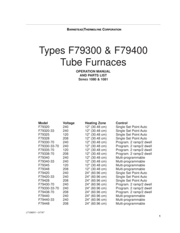
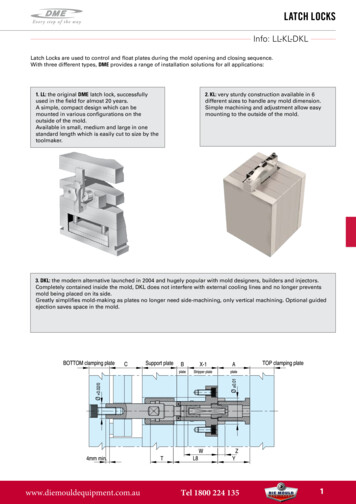
Latch LocksDKLInternal Latch LockDME’s unique internally-mounted latch lock mechanism adapts toa number of mold base sizes and plate thicknesses. It is availablein three sizes to accommodate most standard DME stripper platemold bases. Two travel ranges and two center puller pin lengthsare available for each of the three latch lock sizes. Once installed,DME’s internal latch locks control the sequence of one parting lineopening after the first parting line has traveled a predetermineddistance. After installation there are no adjustments that can beaccidentally changed. The internal latch locks are most commonlyused on DME stripper plate mold bases.BasicLatch 28Small34Medium45LargeREFDKL 2811DKL 2812DKL 2821DKL 2822DKL 3411DKL 3412DKL 3421DKL 3422DKL 4511DKL 4512DKL 4521DKL 4522CenterRecommended max. Max. RecommendedTravel Range (1) PullerPinStandard DMELoad ValuesMin./Max.Length Options Mold Base WidthStatic - Dynamic5 - 3030 - 556 - 4141 - 7612 - 5858 - uller PinY(3)MountingPlateZ(4)C’BareDepth29610 kN - 100 kg4023 0,122 - 3510 0,04039620 kN - 200 kg5132 0,127 - 47,612 0,04059630 kN - 380 kg6843 0,135 - 6016 0,040(1) Supplied to provide maximum travel with no cutoff. To reduce travel between maximum and minimum, cut offslotted travel limiting sleeve on threaded end only per installation data. Cut off to no less than minimum travel;maintain close tolerances per installation data.(2) This set-up dimension is critical and must be maintained as specified to properly locate pin and cam bodyto latch. Dimension W is from top of X-1 stripper plate to top end of center puller pin. See installation data foradditional information.(3) “Y” mounting plate dimension will be the “A” plate for stripper plate mold bases.(4) This counterbore depth is critical and must be maintained as specified to locate split sleeve, cam body and pin tolatch.www.diemouldequipment.com.auTel 1800 224 13518
Latch LocksDKLInternal Latch LockBasic selection and application design guidelines1. Select the appropriate internal latch lock size – 28 mm diameter (small), 34 mm diameter (medium), or 45 mm diameter(large) based on the width of the mold base. However, largemolds, thick plates or heavy load applications may require thenext largest size assembly than is specified.2. Select the appropriate travel range from the two choices foreach size. This selection is based on the specific applicationrequirements for the amount of travel that must occur at oneparting line prior to the latch being released. The total travelrequirements are based on the amount needed for the application as explained above, plus 3 mm minimum additionalallowance. This added 3 mm minimum will make sure the fullrequired travel has occurred before the latch lock starts itsreleasing action.3. Select the appropriate length for the center puller pin fromthe two choices for each size. The length of the pin is determined by the specific application including the mold base platethicknesses, where the pin will be mounted, etc. If possible,the center puller pin should be mounted in the support plate.However, some applications require the center puller pin to bemounted in the bottom clamping plate. This will depend on thetravel or the length of the split sleeve component which controls the travel and the plate thicknesses in the mold base.4. A minimum of four assemblies are recommended per mold.However,for larger molds, thick plates, or an application where loads arenear maximum, additional assemblies and/or next largest sizeassemblies may be required. An application must never exceedthe maximum recommended load values. A balanced loadmust be maintained to avoid cocking and binding which couldcause severe overloading. Only one size latch lock assemblyshould be used in each mold base.5. The center puller pin should be counterbored into its mounting plate 4 mm minimum for most applications, as shown inthe drawings at right. This counterbore aligns the center pullerpin with the other components in the assembly.6. It is important to make sure that the leader pin lengths inall applications are long enough to fully engage the stripperplate through its full travel. The latch lock mechanism latchestwo plates together but is not intended to provide guidance.Instead it relies on the leader pins in the mold for proper alignment and support of the actuated stripper plates.7. In the fully latched position the internal latch lock mechanism will allow movement of approximately 0.4 mm for the 28mm diameter and 34 mm diameter assemblies and approximately 0.5 mm for the 45 mm diameter assemblies.8. Injection molding machine mold opening speed may have tobe reduced in order to make sure that excessive shock loadingdoes not occur.9. The Internal Latch Lock is not recommended for severe loadapplications.10. The Internal Latch Lock must not be exposed to temperatures that exceed 150 C at any time.11. An optional sleeve can be added to the Latch Lock that provides two additional functions. However, this optional sleeveis not required for the Latch Lock function. The optional sleevecan be added to incorporate guided ejection and/or normalejector assembly return functions in the mold.www.diemouldequipment.com.au4 mmMin.Internal Latch Lock application with centerpuller pins mounted in the support plate.This is typically done in applications wherethe travel is shorter and/or when moldplates are thicker.4 mmMin.Internal Latch Lock application with centerpuller pin mounted in the bottom clampingplate. This is typically done in applicationswhere the travel is longer and/or whenmold plates are thinner. (Some applicationsmay require a thicker than standard bottomclamping plate.)Tel 1800 224 13519
Latch LocksDKLInternal Latch lateAssemblyLatchingRetaining ScrewAssemblyREFDKL 2811DKL 2812DKL 2821DKL 2822DKL 3411DKL 3412DKL 3421DKL 3422DKL 4511DKL 4512DKL 4521DKL 4522DKL 11SpringRetainerBody for CamFingers withoutCam FingersBody for CamFingers with 4Cam Fingers*Cam fingerReplacementkit**Spring forHolding PinHolding PinFor CamsDKL 21DKL 31DKL 32DKL 62DKL 41DKL 51Slotted Travel Limiting SleeveDKL el 1800 224 135Center Puller PinT ravelDKL 81/82rangeDKL-20815 - 30DKL-2082DKL-208130 55DKL-2082DKL-30816 - 41DKL-3082DKL-308141 76DKL-3082DKL-408112 58DKL-4082DKL-408158 310020
Latch LocksDKL11Assembly retaining DKL-4041SizeD15L18SmallMediumLarge6,589,7567090Ø D15Spring for holding pinDKL51Holding pin for 1Spring retainerREFDKL-2021DKL-3021DKL-4021SizeD4D5D6Small 12,6 M16x1 6,8Medium 15,0 M19x1 8,3Large 17,2 M24x1 www.diemouldequipment.com.auTel 1800 224 13521
Latch LocksDKL62Cam finger replacement mLarge5,87,294,24,86,0DKL32Body for cam fingers - with cam fingersR1D13REFDKL-2032SizeD8Small 54D9D10L8L9L12L14L1520,6 M16x1 401374012,6 2,5DKL32R1Drill ØC’bore ØC’bore depthMetric S.H.C.S.6,810,46,8M6x1Body for cam fingers - with cam geD9D10L8L9L12L14L1524,4 M19x1 5132,4 M24x1 681520810466012,6 2,5174www.diemouldequipment.com.auR1Drill ØC’bore ØC’bore depthMetric S.H.C.S.6,88,410,413,76,88,5M6x1M8x1,25Tel 1800 224 13522
Latch LocksDKL71/72Slotted travel limiting KL-4072SizeTravel diumMediumLargeLarge5- 3030- 556- 4141- 7612- 5858- L81/82Center puller pinTap after 15,59,522M12x1,75www.diemouldequipment.com.auTel 1800 224 135Metric23
Latch LocksDKLGuided Ejection SleeveAdd guided ejection and return pin functions to Internal Latch Lock mechanism with this optional sleeveThe optional Guided Ejection and Return Sleeves, although notrequired for the Internal Latch Lock, can add two functions tothe mold base that are typically required in most molds. Theseoptional sleeves can add guided ejection and ejector assemblyreturn functions to the mold base. Additionally, these addedfunctions fall within the space requirements of the plate latchingmechanism. However, these optional sleeves do not create anearly ejection return system that is occasionally required in someapplications. Sleeves can add guided ejection function to mold base alongwith plate latching mechanism Sleeves can replace function of return pins in mold base for mostapplications using the plate latching mechanism Sleeves fit around the center puller pin of the plate latchingmechanism and are mounted in the ejector assembly, thus eliminating the need for additional mold space usually required for theguided ejection and return pin functionsCut off only on this end;refer to note 1 below.L35L39L40 1.6 1D30 Dia. 0.02 0D29 D28 D30Dia. Dia. Dia.-0.01-0.03 0.02 0D28Dia.D28Dia.L36L38 0.9 um)45.(Large)REF 1DKL-4102DKL-4102Optional – Guided Ejection and Return Sleeve FeaturesD29D30L36L37L38ØØLength Thickness 62618820704020Notes:1. Choose the appropriate length sleeve so that it can becut off to a length that will fully return the ejector assembly. See installation data.2. The center puller pins must support and guide thesleeves, as well as the ejector assembly. The pins musthave sufficient bearing surface contact as specified bydimension “L41” minimum.3. Additional bearing surface contact for the center pullerpins may require a thicker bottom clamping plate or theaddition of another plate to the bottom of the mold forsome applications.www.diemouldequipment.com.au4. A minimum of four assemblies are typically recommended per mold. However, for larger molds, thick plates,or an application where loads are near maximum, additional assemblies and/or next largest size assembliesmay be required. An application must never exceed themaximum recommended load values. A balanced loadmust be maintained to avoid cocking and binding whichcould cause severe overloading. Only one size Latch Lockassembly should be used in each mold base.Tel 1800 224 13524
Two-Stage EjectorsFW18002-stage ejectors are used in situations where two ejection sequences are required, for example, to demold undercutswith inclined cores or ensure that slides do not collide with ejector pins. DME’s range of two-stage ejectors systems offertwo types of functionality.1. Ejector Plates Back2. First Ejector Stroke3. Second Ejector Stroke“Bottom last” using FW 1850 and TSBL types: 1st movement: both sets of ejector plates, 2nd movement: bottom set ofejector plates.1. Ejector Plates Back2. First Ejector Stroke3. Second Ejector Stroke“Top last” using FW 1800 and TSTL types: 1ste movement: both sets of ejector plates, 2nd movement: top set of ejectorplates.&&Furthermore, two versions of installation are available:Central mounted using FW 1800 and FW 1850: this is thesimplest installation for smaller, less complex molds. Asingle unit (FW 1800 or FW 1850) is connected directly tothe machine ejector rod.www.diemouldequipment.com.auOff-centre mounted using TSTL and TSBL: fully containedinside the mold preventing interference and accidentaltampering. Useful where the central space is not available. Two or four units are used allowing larger molds.Tel 1800 224 13525
Two-Stage EjectorsFW1800REFFW1800 M32x1,5FW1800 M42x1,5FW1800 M52x1,5FW1800 M62x1,5REFFW1800 M32x1,5FW1800 M42x1,5FW1800 M52x1,5FW1800 M62x1,5Two-Stage Single-Stroke W2A 27354456100152215*Recommended threadwww.diemouldequipment.com.auTel 1800 224 13526
Two-Stage EjectorsAssembly FW1800Two-Stage Single-Stroke ejector*Recommended thread1. Ejector rod2. Sliding sleeve3. Adjusting bush4. Assembly flange5. Segments6.PartStopringdesignation7. SpacerNr. 1 Ejector pin2 Sliding sleeve3 Adjusting bush4 Assembly flangeFitting:5 Segment1. Mountejector rod no. 1 together with ejector plate. For safety please use LOCTITE C 242.6 Stopringparts no. 2, 3 and 4 together and tighten up part no. 3 (SW2 see chart).2. Moveover7 Spacer3. Tightenupringadjusting bush no. 3 with assembly flange no. 4.4. Fix assembly flange.Recommended lubricants: C 135, C 138/139, C 170, etc.Installation instructions:This device is preferably screwed together with the hydraulic machine ejector.The required internal or external thread of part no. 1 has to be made adequately. The ejector rod no. 1 may not beshortened by more than length k1, if the total stroke h3 (h3 h1 h2), including a possible deeper run in of part no.1 into part no. 2, is not be maintained.By rotating adjustment of bush no. 3 the first stroke h1 is continuously adjusted. With stroke h1 both ejectorpin plates are moved simultaneously. On the following stroke h2 only the second ejector pin plate movement iscontinued. Choose the thickness of the spacer ring no. 7 so, that there is at least 0,05 mm clearance between theejector pin plates (see fig. 1).www.diemouldequipment.com.auTel 1800 224 13527
Two-Stage EjectorsFW1850Two-stage single-stroke ejectorThe two-stage single-stroke ejector can beintegrated into injection molding tools.This ejector automatically divides themotion into two sequential strokes.The functional sequence associated withthis makes it possible to create new moldejection mechanisms.Through hardLeft-handed threadThrough hardREF d x H1 maxH1 maxH2d1d2d3d4d6d7d8d9d10FW1850 50x32FW1850 58x40FW1850 58x56FW1850 x1,50M6x16M8x20M8x20M8x2562727284REFl2l3l4l5l6l7 max.l8 max.SW1SW2SW3SW3NmSW4SW5SW6FW1850 50x32FW1850 58x40FW1850 58x56FW1850 5555656881027323238www.diemouldequipment.com.auTel 1800 224 13528
Two-Stage EjectorsAssembly FW1850Two-stage single-stroke ejectorEjector plate assembly IIEjector plate assembly ISupport plateClamping plateFeatures: Secured position of the ejector plates due to builtin-low-wear interlocks. Infinitely variable strokes High operational reliability of the ejectorcomponents due to forcedcontrolled stroke actions Simplified operations of angled and rotating moldejection components. Space-saving installation in the ejector bolt area. The tool height remains unchanged.www.diemouldequipment.com.auDesign considerations:A detachable fixed connection between ejector bolt (FW1850) and the machine ejector is necessary, preferablyusing the pneumatic rapid-action coupling PN 1680.The ejector plates cannot be pushed by return pins dueto the tool closing movement! Ejector plate guidanceby four guides in the ejector plates to prevent tilting. Astroke limitation is preferable to keep the ejector platesseparate in the end position. Centre misalignmentcompensation between machine ejector and toolpreferably by pneumatic rapid-action coupling PN 1680.Adapter for tool on MAP will be made, as necessary,preferably from centering flange R 19.Tel 1800 224 13529
Two-Stage EjectorsTSTL2-stage Ejector Top LastPositive, precise plate control:DME 2-stage Ejectors (TS) adapt to a number of mold base sizez and plate thicknesses. They are available in two ejection sequences: Top Last (TS) and BottomLast (BS). Each ejection sequence is available in three sizes to accommodatemost standard DME mold bases. The stroke range for each ejection stage isdetermined and fixed by the customer by cutting the Center Rod to the desiredlength (both TSTL and TSBL types) and by also cutting the Travel Sleeve to thedesired length (TSBL type only). Once installed, the DME 2-stage Ejector assurespositive, precise control of the sequence and distance of each stroke of the twoejector plates. Once installed, there are no adjustments that can be accidentallychanged.Benefits:Both the first stage and second stage strokes are set independently. Easy set-upand installation. Fixed strokes cannot be tampered with or accidentally modified.Internal installation avoids interferences with water line connectors and externally mounted components. Utilizes latching mechanism similar to DME InternalLatch lock for smooth operation and guidance. Three sizes, for each style, to choose from to accomadate most standard DME moldbases. Hardened steel components for long life. DME 2-stage Ejectors are considerably more compact and may be centrally located,the preferred method for locating DME 2-stage Ejetors is in pairs, offset from mold center. For more details, assembly guidelines seewww.dme.net.Selection and design guidelines:Select 20 mm Ø (small), 26 mm Ø (medium), or 23 mm Ø (large) 2-Stage Ejector based on the width of the mold base (large molds,thick plates or heavy load applications may require the next size assembly). Determine the travel range for each ejection stroke(first and second), being very careful not to exceed the maximum stroke specified for the chosen 2-Stage Ejector style and size.this selection is based on the specific application. In general, a minimum of two 2-stage Ejectors are required. For larger molds,thick plates, or a application where loads are near maximum, additional assemblies and/or larger assemblies may be required. Anapplication must never exceed the maximum recommended laod values. A balanced load must be maintained to avoid cockingand binding which could cause severe overloading. Only one size of 2-stage Ejectors should be used in each mold base.H1-Stroke 1H2-Stroke 2Basic centerrod d
mold being placed on its side. Greatly simplifies mold-making as plates no longer need side-machining, only vertical machining. Optional guided ejection saves space in the mold. 2. KL: very sturdy construction available in 6 different sizes to handle any mold dimension. Simple machining and adjustment allow easy mounting to the outside of the mold.