Transcription
Page 1 of 10 Load Cell Amplifier HX711 Breakout HookupGuideGetting StartedThe HX711 load cell amplifier is used to get measurable data out from aload cell and strain gauge. This Hookup Guide will show you how to getstarted with this amplifier using some of the various load cells we carry atSparkFun.What You Will Need:For this simple hook up guide we will just be hooking up a load cell with theHX711 amplifier, and showing how you would hook up four load sensorswith a combinator board and the HX711 amplifier. To follow along, you’llneed: SparkFun Load Cell Amplifier - HX711 Any Strain Gauge Based Load Cell:Load Cell - 200kg, Disc(TAS606)Load Cell - 50kg, Disc(TAS606) SEN- 13332 SE N-1 3331
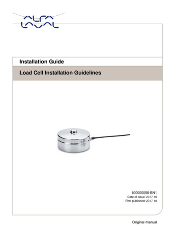
Page 2 of 10Load Cell - 10kg, StraightBar (TAL220)Load Cell - 10kg, Wide Bar(TAL201) SEN- 13329 SE N-1 3330If you are planning on using load sensors1 you will need to obtain orpurchase four units. We recommend our Combinator Board to make it easyto turn the four strain gauges into a wheatstone bridge type load cell.(Single strain gauge load cells only have three wires instead of four.)Suggested ReadingIf you aren’t familiar with the following concepts, we recommend reviewingthem before beginning to work with the HX711 Load Cell Amplifier Board. Load Cell BasicsGetting Started with Load CellsInstalling the Arduino IDEHow to Power Your ProjectBattery TechnologiesHow to Solder1. [Strain gauges are two wired organized metal foil or wires that are set up in such a way that the resistance changeswhen it is compressed or stretched. When a strain gauge is placed on something (usually metallic in nature) itsresistance changes based on the stress experienced by that something. When a single strain gauge is hooked up to ametallic cell, we are calling that a load sensors, which have three output wires. Load cells usually has four strain gaugeshooked up in a wheatstone bridge formation, which have four output wires. For more information on load cells, straingauges, and wheatstone bridges see our tutorial.] Load Cell Set UpA selection of different load cellsDepending on the type of load cell you are using, the configuration of how itshould be hooked up to plates or surfaces will change. Below are a fewdifferent types of setups.
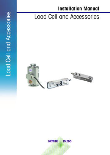
Page 3 of 10Bar load cell between a two plate configurationS load cell configurationPossible four disc load cell configuration in something like a bathroom scaleBar strain gauge based load cellsUsually with larger, non-push button bar load cells you will want to hook upthe load cell between two plates in a “Z” shape, with fitting screws andspacers so that the strain can be correctly measured as shown below:
Page 4 of 10Note that only one side of the load cell is screwed into each board. Thisprovides a moment of force, or torque, on the strain gauge rather than justcompression force, which is easier to measure and much more accurate.For smaller, push-button or disc load cells, you will want to make sure toscrew in the disc to a bottom plate (or surface you are measuring forceagainst), and center the beam, plate, or whatever else you are wishing tomeasure the force of onto the “button” on the top. Usually another plate witha hole is used to make sure whatever you are measuring is hitting the samespot on the load cell each time, but it is not necessary.Make sure to read the datasheet for the load cell you are using and get thecorrect screws to fit into it. Note: If you are hooking together four of the SparkFun Load Sensorsusing the Combinator board, you should position the four loadsensors equidistant from each other, just like the bathroom scalesshown in this tutorial.Load cell measurements can be off by /- 5% due to a range of thingsincluding temperature, creep, vibration, drift, and other electrical andmechanical interferences. Before you install your scale, take a moment anddesign your system to allow for easy calibration or be able to adjust thecode parameters to account for these variations.Hardware Hookup
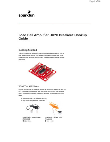
Page 5 of 10The HX711 Load Cell Amplifier accepts five wires from the load cell. Thesepins are labeled with colors; RED, BLK, WHT, GRN, and YLW. Thesecolors correspond to the conventional color coding of load cells, where red,black, green and white wires come from the strain gauge on the load celland yellow is an optional ground wire that is not hooked up to the straingauge but is there to ground any small outside EMI (electromagneticinterference). Sometimes instead of a yellow wire there is a larger blackwire, foil, or loose wires to shield the signal wires to lessen EMI.Four strain gauges (SG1 through 4) hooked up in a wheatstone bridgeformationHere we have a large black wire, some loose wires, and foil and loose wiresrespectively as EMI buffersIn General, each load cell has four strain gauges that are hooked up in awheatstone bridge formation as shown above.The four wires coming out from the wheatstone bridge on the load cell areusually: Excitation (E ) or VCC is redExcitation- (E-) or ground is black.Output (O ), Signal (S ) or Amplifier (A ) is whiteO-, S-, or A- is green or blue
Page 6 of 10Some load cells might have slight variations in color coding such as blueinstead of green or yellow instead of black or white if there are only fourwires (meaning no wire used as an EMI buffer). You might have to infer alittle from the colors that you have, but in general you will usually see thesecolors.If the readings from the HX711 are opposite of what you are expect(for example the values decrease as you increase weight) simplyreverse the O /O- wires.Once the load cell is is hooked up to the amplifier, you can hook up VDD,VCC, DAT, CLK, and GND to a microcontroller such as a RedBoard orArduino board.Note VCC is the analog voltage to power the load cell. VDD is the digitalsupply voltage used to set the logic level.PRO TIP: In many cases, you can just short VCC and VDD together. Ifyour microcontroller uses 3.3V logic however, you'll want to connectVCC to 5V and VDD to 3.3V.Load cell wires hooked up to the HX711 Amplifier boardThe example code has DAT and CLK hooked up to pin 3 and 2respectively, but this is easily changed in the code. Any GPIO pin will workfor either. Then VCC and VDD just need to be hooked up to 2.7-5V andGND to ground on your microcontroller.Fritzing diagram of HX711 amplifier connected to a RedBoardNow, if you would like to set up four single load sensors with ourcombinator board and amplifier, connect the five pins labeled RED, BLK,WHT, GRN, YLW to the matching pins on the HX711. Next, connect eachof the four load sensors to the following pins: Red Black White C
Page 7 of 10The combinator board also has room for an 8 pin RJ45 socket, which canbe used to connect your project via Ethernet cables for long distanceapplications.Another nice thing about our combinator board is that most home scalesuse four single strain gauge load sensors, so this is a handy board forhacking your own scales at home!Hacked home scale’s four load sensors hooked up to our combinator boardExample of a single strain gauge, or load sensor. Here RED is the centertapFor load sensors, there isn’t a set color coded standard. Comparing thescale pictured above with the load sensor schematic, while the black wiresmatched, the red and white wires were swapped. Also, only two of the foursensors used a white wire for the ‘center tap’ of the load sensor, the othertwo used green. I connected the black wires to “-”, the red to “ ”, and thewhite and green wires to “C”.To determine how to hook up your single strain gauge load cells to thecombinator, measure the resistance between the three wires. You shouldfind a larger resistance (close to double) between a pair. In our example theresistance between red and black was 1.6 kΩ, and the resistance betweenwhite/green and red was 800 Ω. Therefore, the center tap to the straingauge is the white/green wire. The center tap or center pin of your straingauge connects to the “C” pin on the combinator. The larger resistancewires (red and black in this example) connect to the “ ” and “-” pins on thecombinator.
Page 8 of 10The combinator board hooks up the four load sensors in such a way thattwo resistors in the wheatstone bridge configuration are constant valuesand the other two are variable in this way:To hook up the combinator board to the HX711 match the RED, BLK, WHT,and GRN pinsOnce you have the combinator board successfully soldered to the twelvewires, you can now connect it to the HX711 amplifier board via the 4standard load cell wires. You can use short jumper wires or if yourelectronics are a long distance away from your scale consider using anRJ45 connector and an ethernet cable to connect the combinator to theHX711 amplifier.Arduino CodeNow that you have your load cell, amplifier, and microcontroller hooked up,you can add your code and start calibrating your setup.You can download the most up-to-date code and libraries from the linkbelow.G I T H U B RE P O S I T O RYIf you have never worked with downloading Arduino libraries or need aquick reminder you might want to take a look at our tutorial on InstallingArduino Libraries.Or you can easily get started and running with everything in Codebender!The first thing you will want to work with is the calibration code:“SparkFun HX711 Calibration”:
Page 9 of 10SparkFun HX711 Calibration(https://codebender.cc/sketch:123175?[ EditÈ Clone & Edit3 Download referrer sarahalmutlaq)bysarahalmutlaq1 /*(/?(https://codebende2Example using the SparkFun HX711 breakoutboardwith a sca (https://codebender.cc/user/sarahalmutlaq?referrer 4252627282930By: Nathan SeidleSparkFun Electronicsreferrer sarahalmureferrer sarahalmutlaq)Date: November 19th, 2014License: This code is public domain but you buy me a beerThis is the calibration sketch. Use it to determine the caoutputs the zero factor useful for projects that have a peSetup your scale and start the sketch WITHOUT a weight onOnce readings are displayed place the weight on the scalePress / or a/z to adjust the calibration factor until thUse this calibration factor on the example sketchThis example assumes pounds (lbs). If you prefer kilogramscalibration factor will be significantly different but itYour calibration factor may be very positive or very negatand the direction the sensors deflect from zero stateThis example code uses bogde's excellent library: https://bogde's library is released under a GNU GENERAL PUBLIC LICTo programArduinoArduinopin 2 your HX711CLKfrom your browser, please use3 romium5V VCCGND 41GNDand above on Linux) or Mozilla ox/)only on Windows).Most any pin on the Arduino Uno will(32bitbe compatiblewith DO DismissPlease select a board Once you have calculated your calibration factor of your load cell set up,you can move on to other code, such as the simple scale output examplecode, “SparkFun HX711 Example”:SparkFun HX711 Example(https://codebender.cc/sketch:122922?[ EditÈ Clone & Edit3 Download referrer sarahalmutlaq)by sarahalmutlaq1 /*(/?(https://codebende2Example using the SparkFun HX711 breakoutboardwith a sca (https://codebender.cc/user/sarahalmutlaq?referrer 4252627282930By: Nathan SeidleSparkFun Electronicsreferrer sarahalmureferrer sarahalmutlaq)Date: November 19th, 2014License: This code is public domain but you buy me a beerThis example demonstrates basic scale output. See the calispecific load cell setup.This example code uses bogde's excellent library: https://bogde's library is released under a GNU GENERAL PUBLIC LICThe HX711 does one thing well: read load cells. The breakobased load cell which should allow a user to measure everyArduino pin 2 HX711 CLK3 DAT5V VCCGND GNDThe HX711 board can be powered from 2.7V to 5V so the Ardu*/ To program your Arduino from your browser, please useGoogleChrome (http://www.google.com/chrome/)/Chromium#include "HX711.h"(version 41 and above on Linux) or Mozilla Firefox#define calibration factor 7050.0 //This value is obtained(http://www.mozilla.org/en-US/firefox/) (32bit only on Windows). #define DOUT Dismiss3Please select a board Check out the other example code in the Github repo, or Codebender forpowering down the HX711 (github, codebender) and known zero startup(github, codebender).
Page 10 of 10Resources and Going FurtherWant to know more? Check out this tutorial if you haven’t already:Getting Started with Load CellsJ UNE 11 , 2015A tutorial defining what a load cell is and how to use one.Need even more? Check out this awesome article wheatstone bridges andload cell ll-amplifier-hx711-breakout-hookup-guide9/9/2016
Example using the SparkFun HX711 breakout board with a sca By: Nathan Seidle SparkFun Electronics Date: November 19th, 2014 License: This code is public domain but you buy me a beer This is the calibration sketch. Use it to determine the ca outputs the zero_factor useful for projects that have a pe