Transcription
Follow us onwww.erm-automatismes.comAbout usERM provides technical systems and services in the fields of education, robotics, manufacturinglaboratories (FabLabs), energy and industry. Founded in 1990 in southern France, ERM firstfocused on industrial automation. Overtaken by its educational culture, ERM quickly became theprecursor of introducing industrial production lines within technical training institutions. Uponrequest by these educational institutions, ERM then extended its offer to other areas, such aselectronics, electrical engineering, power engineering and renewable energy.Today, ERM has become a market leader in didactic solutions and systems for technological andvocational training in France, and is developing its export markets.More than 1500 academic institutions are equipped with ERM technical teaching equipment inFrance: Secondary schools for vocational training, Vocational training centers, Universities,Universities of Technology, Major engineering schools, etc.Abroad, many vocational training institutions are using our systems: French overseas territories: Guadeloupe, Guyana, Reunion, Martinique, Mayotte, NewCaledonia, French Polynesia, Wallis & Futuna Africa : Algeria, Burkina, Cameroun, Gabon, Ivory Coast, Morocco, Mauritania, Senegal,Tunisia, Asia : Vietnam, Korea America : Mexico, Colombia Europe : Belgium, Luxembourg, Romania, Hungary, Slovakia, Switzerland
More information on:www.erm-automatismes.comElectronics & CommunicationInstruments, tools and dataacquisition : See pages I8 to I9NAO Humanoid Robot & Subsystems for mechatronicsToken dispenser with embedded PCElectronics Prototyping ProjectsMulti-function power electronic converters –NI USRP Universal Software Radio Peripheral –Training platform for digital wireless communicationsMulti-function IGBT or diode & thyristor converterswith close control and protectionG1
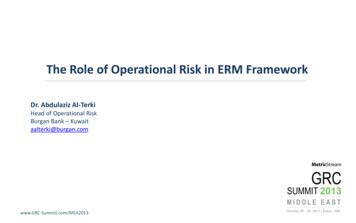
Robotics & AutomationNAO Humanoid RobotNAOtronics - Three training modules for the exploration of technology solutions implemented inthe NAO robotIn partnership with Features: Audio (4 microphones and 2 loudspeakers) Video (2 HD cameras 1200 x 960) Inertial unit (3-axis accelerometer, and 2-axis gyrometer) and Sonars Sensors (pressure FSR, bumpers, tactile) Servo-motors (coreless motors with hall effect sensors) Grip (prehensile hands with 3 operable fingers) Intel Atom 1.6 GHz CPU with 1 GB RAM and 8 GB Micro SDHC (text-tospeech, Image and voice recognition )Pages WiFi and Ethernet modulesH2/H3 Lithium-ion battery (90 minutes autonomy) Training activities: Functional analysis and SysML description Information chain architecture Study of motion and communication Study of controllers used on NAOChoregraphe programming Development and testing of new algorithms (eg: sight )software Project: Develop applications for NAO, invent missions for NAO Project: Design software architecture for activities (eg: NAO monitors a room) Key points: Motivating and fun for students, and a medium of communication for theinstitution Open environment (Software suite for programming and data logging.) Reference: AR//H25-EA: NAO humanoid Robot with SDK, Choregraphe, Webots 3D simulation softwareMonitor, 10 licenses - AR//SW-CSDK-U: Software suite Choregraphe, Monitor,SDK, site license - AR//SW-WNAO: Webots software for NAO, 1 license AR//SW-WNAO10: Webots software for NAO, 10 licensesTraining system for NAO Foot Ankle control Features: Mechanical transmissions (gears, gear reducer ) Motors (DC motors) Sensors (magnetic position sensors)Compatible with SPI electronic busthe ”Motors & MotionLab” bench Training activities:Page H6 Studying a DC / DC static converter Influence of a PI corrector Model of pitch behavior Impact of sensor position on control Key points: Ideal resource to teach about design and servo control for biaxial systems Viewer software for communication with and control from a PC Electronic diagrams to study constructive solutions Reference: NA11: Training system for NAO “Foot Ankle” control - PR09: USB Logic Analyzer (to see the framesrunning on the SPI electronic bus)NAOtronics DetectionNAOtronics Motorization NAOtronics Communication Features: FSR pressure sensors MRE position sensors Inertial measurement unit Ultrasonic (sonar) sensors Infrared sensors Mechanical contact (shock)sensors Capacitive (touch) sensors Sound (microphone) sensors Arduino UNO development pack Features: DC motor with reducer Servo motor Electric cylinder Humanoid finger Arduino and Raspberry Piboards, to control theactuators Human-Machine Interface(LCD screen, keyboard ) Features: SPI/I2C communication RS485/CAN communication Ethernet communication WiFi communication Arduino UNO development pack Training activities: Analysis of sensors in aninertial measurement unit:accelerometer and gyroscope Analysis of ultrasonicsensors for distance Analysis of FSR forcesensors Analysis of MRE angularposition sensors Training activities: Studying the mechanicalconnections, kinematics,mechanical transmissions,motors and control SED programming in Pythonon Raspberry Pi and Arduinoon microcontroller Training activities: Study and analysis of the mainprotocols Communication:analyzing/modelling andexperimenting on the informationchain Experimenting with differentnetwork technologies Key points: Ideal training support for studying multi-physics technology solutions anddeveloping skills and knowledge in a training module Electronic diagrams for studying constructive solutions using sensor behaviorpatterns References: NA15 PR00 PR30 PR31 PR32: NAOtronics « Detection »pack - DR10: Humanoid finger (NAOtronics Motorization pack) –PR00 PR10 PR11 PR18: NAOtronics « Communication » pack – PR09:USB Logic Analyzer (to see the frames running on the SPI electronic bus)www.erm-automatismes.comG2
Embedded systemsEmbedded electronic system for vehicles – Studying and commissioning an embeddedToken dispenser with embedded PC - Studying a token dispenser and its embeddedelectronicsindustrial PC for vehicle simulation with data reporting Features: Communications bus (Profinet, Wifi) Communication components (gateways, WiFi accesspoint, SIP telephone, PABX, router) Embedded PC (Microbox Siemens, inverter) Human Machine Interface (colour touch-screen) Electronic sensors (inductive coil, brightness, impact.) Actuators (micro-motors, lighting, voice, alarm ) Security (video monitoring, alarm control, RFID accesscontrol) Programming and configuration software (WinAC RTX,WinCC Flexible)In partnership with Features : Communications bus (CAN) Communication components (converters, ECUdevice) Embedded PC (Microbox Siemens) Automotive sensors & actuators (starting, gasoline,lighting, speed ) Simulation & diagnostic software (CAN Explorer,Microbox software) Training activities : Situation scenario & introduction to system operation Installation, commissioning and connection Analyzing the electrical signal of the control panel Digital signal analysis of the CAN bus Hardware and software configuration of the embedded PC System diagnostics Key points: Multi-scenario open platform for the study of embedded systemsCAN Explorer software Configuring and commissioning an industrial embedded PC Conduct studies and obtain theoretical measurements (Software) & physical measurements (Measuring pointson terminals) Compact system References: VH10: Embedded electronic system for vehicles – VH11: Unit for configuring and commissioning anEmbedded Microbox PC (Included: 1 Microbox and 24V power supply, 1 Vehicle simulation application, 1CANExplorer software, 1 CAN/PC converter PC104) – VH12: Microbox Embedded PC (without software) for Hardwareand OS installation Training activities: Situation scenario and introduction to system operation Installation, commissioning and connection Integration and commissioning of extensions Networking non communication-capable equipment System adjustment and configuration Software configuration of the embedded PC Industrial WiFi configuration Troubleshooting and Maintenance Key points: This system may be used for electrical certification Common “embedded” application Technological diversity Upgradeable system enabling real interventionsTouch-screen withembedded PCIndustrial WIFI access point Reference: DJ20: Token dispenser with Embedded Siemens Microbox PC – DJ12: Automated lighting and vandalresistant kit (Optional)– DJ13: Voice guidance kit (Optional) – DJ15: Kit for integrating a second dispenser for newtoken format (Optional) – DJ16: Industrial WiFi kit and video monitoring camera with software and recording on NASserver (Optional)Embedded PCView of simulatorChange machine and tokendispenserwww.erm-automatismes.comDJ12: Option Automated lightingand vandal-resistant kitDJ13: Option Voiceguidance kitG3
Embedded systemsNetworks & TelecommunicationsAerial imaging gimbal – Studies and projects on a 2-axis controlled gimbalMicrowave educational bench & Antennamounted on a drone Features: Inertial measurement unit (accelerometer and gyroscope) Motorization & Energy (brushless, DC and stepper motors, industrialmotor controller board) Mechanical linkage solutions Video and image processing (camera) Real-time LabVIEW control (MyRIO board) Communication (CAN bus)Video control camera Training activities: Testing of gimbal performance Motorization impact on gimbal behavior Behavior pattern of the controlled pitch axis of the gimbal Impact of axis balancing on performance Image control and recognition Impact of control sampling frequency Sensor impact on gimbal performance Analysis of coupling phenomena Analysis of gravity (direction) impact Power supply impact on performance Designing a camera stabilization system Study of sensors (accelerometer, gyroscope) Real-time LabVIEW programming Configuration of industrial motor controllers Study and configuration of a CAN bus Projects: Design of a third axis (mechanical linkage – brushless, DC or stepper motor - Arduino/Pythonelectronics and programming)Compatible with Key points:the”Motors & Motion Opportunity to compare different technologies and motor powersLab” bench Image analysis and integration in the position control loopPage H6 Opportunity to implement projects using a third motorized axis Control programming/modification in Python Two types of control: Embedded electronics Real-time industrial electronic platform, based on NI myRIO References: NC10: Aerial imaging gimbal – NC10 NC15: Aerial imaging gimbal with real-time video camera –NC10 NC00 NC09: Aerial imaging gimbal with real-time electronic platform (NI myRIO board and controller for 2brushless motors) – NC10 NC15 NC00 NC09: Aerial imaging gimbal with video control camera and real-timeelectronic platform (NI myRIO board and controller for 2 brushless motors) – NC11: Gimbal with more powerfulmotors (Optional) – NC15: Video control camera – NC16: Third-axis motorization kit with brushless/DC/steppermotor controller (Optional) – NC00 NC09: Real-time electronic platform (NI myRIO kit and controller for 2 brushlessmotors)Interface for configuration,measurement and imageanalysis with LabVIEWIn partnership with Features: GUNN diode oscillator Ferrite isolator PIN diode modulator Micrometer attenuator Cavity wavemeter Measuring line Impedance adaptor Waveguide-to-coax transition element Adapted load Short-circuit platelet Guide support Training operations: Study of microwaves and of guided electromagnetic wave propagation Study of a GUNN oscillator Measurement of impedance, wavelength, frequency and SWR (standing wave ratio) Determination of a detector’s quadratic law Study of antennas and of free-space propagation of electromagnetic waves 10 GHz energy radiation method by means of various antennas Study of space attenuation as a result of wave polarization and gain measurement Obtaining a radiation chartMounted bench with components Key points: Rectangular waveguide technology in accordancewith the R100/WR90 standard covering a rangebetween 8.5 and 9.6GHz Clever assembly system using EASYFIXTM quickfastening A range of antennas for studying free-spacepropagation Training and tutorials suppliedAdd-on:SWR IndicatorAdd-on:Microwave powermeter References: CA//BDHR100: Microwave educational bench – There are many components and accessories forguided and free-space wave propagation and specific instrumentation – Contact us.www.erm-automatismes.comG4
Networks & TelecommunicationsOptical fiber - Studying, implementing and testing FTTH (Fiber To The Home)networksNI USRP Universal Software Radio Peripheral – Training platform for digital wirelesscommunications Features: Optical fiber connection (Fusion splicing or Cold welding) Installation control by reflectometry Connector inspection and cleaning Continuity test and photometry measurements Architecture and laying of FTTH networks Active network simulation Training activities: Learning the basics of optical fiber and its applications in theresidential, tertiary and industrial sectorsOptical fiber / Ethernet network: Defining network architecture (ring, etc.) according tospecifications Working with fiber and connectors Software addressing and configuration of switches Measurements and installation file (with appropriate tools) Communication testsVideo surveillance: Connecting and configuration of the IP/PoE camera Setting up supervision (alarm control) on softwareCounting and remote control via PLC: Wiring and electrical connections Communication configuring Programming or modification of controller programs Development or modification of the supervision applicationIn partnership with: Features: Real-time communication with 2 RF transceivers from 50MHz to 2.2 GHz (25 MHz bandwidth) Covering of the following frequency bands: ISM, FM,GPS, GSM, Wi-Fi, Bluetooth, ZigBee, Radars LabVIEW modulation toolkit High-speed analog-to-digital conversion (ADC)architecture Digital-to-analog conversion (DAC) architecture withFPGAOptical fiber sub-distributor andOperator conveyance box(FF12) Training activities: AWGN (additive white Gaussian noise) simulator, modulation, demodulation, pulse shaping, energy detection,equalization, frame detection, frequency correction and synchronization, etc. Studying the components of a digital communication modem Design of an OFDM (Orthogonal Frequency Division Multiplexing) radio Analysis of signals (dynamic spectrum management) and study of the main wireless protocols2D structure(FF17)LabVIEW toolkit3D structure(FF11) Key points: Selection of materials that allows a comprehensive approach of the different types of technologies,architectures and tools Teaching guide with procedures and tutorials References: FF10: Optical fiber FTTH tool kit - FF20: Optical fiber FTTO tool kit - FF30: Urban monitoring andcontrol networks kit (“industrial” optical fiber)Measuring tools and instruments for optical fiberOptical fiber connection (core- or clad-alignment fusion splicer and cleaver, mechanical splice kit, optical fibertechnician tool kit)Connector inspection and cleaning / Optical fiber visual or digital fault location – Optical link budgets (singleand multimode photometry kit, single- and multimode optical fiber reflectometer/OTDR)Network qualification and certification (Ethernet and Optical fiber wiring and network qualifier, single- andmultimode optical fiber certifier)Fiber / Ethernet media convertersUSRP architecture Key points: Ideal for experiments on RF communications (tutorials provided) Increased productivity due to the LabVIEW graphical measuring and programming interface Teaching guide for studying the components of a digital communication modem and designing an OFDM radio Software radio and RF enclosure enabling full duplex communication Integration of its own algorithms in the software radio under LabVIEW References: NI//781908-01: Set of 2 NI USRP-2920 software radios (50 MHz to 2.2 GHz covering ISM, FM, GPS,GSM and radar frequency bands) with accessories (MIMO cable, 30dB attenuator) and laboratory manual –NI//781915-01: Triple-band antenna 144, 400 and 1200MHz for USRP-2920 - NI//781909-01: NI USRP-2922software radio (400 MHz to 4.4 GHz covering GNSS, Wi-Fi, Bluetooth, ZigBee frequency bands, other ISMapplications and radar L band) with accessories and laboratory manual – NI//781913-01: Dual-band antenna 2.42.48GHz and 4.9-5.9GHz for USRP-2922 – NI//782922-3502: LabVIEW Academic Premium Suite (1 user) licensewww.erm-automatismes.comG5
Electronics PrototypingErmaBoard – Electronics prototyping platform (control circuits, communication, sensors, HMI,robotics, multimedia) Features: Electronic control (microcontrollers, FPGA, ARM9 ) Power supply (battery, solar cell) Communication (Ethernet, Bluetooth, RFID, Zigbee, GPS, WiFi, CAN ) Sensors (temperature, accelerometer, proximity ) Human-Machine Interface (LCD, keyboard, voice recognition ) Robotics/Mechatronics (relays, servomotors, mobile robot chassis .) Multimedia (MicroSD card, JPEG imager, MP3 decoder ) USB logic analyzer for the study of serial protocols PR02 : FoxBoard (ARM9) PR01 : Arduino compatible ERM (PIC 18)PR03 : FPGA Altera (Cyclone 4)PR04 : Bus Pirate (PIC 24)TerminalPythonPR05 : Raspberry PI (ARM Cortex A7)PR00 : Arduino UNO (Atmel Atmega)Quartus IIPhP GCCLIFA LabVIEW MPLAB IDEMinibloq FlowcodeArduino IDE Training activities: Architecture of electronic control systems Principles of microcontrollers, FPGA and microprocessors (ARM9) operating principles as well as theirapplications Programming the microcontroller, FPGA, and microprocessor ARM9 with the provided libraries Communications protocols Prototyping electronic control systems Project 1 : Design and fabrication of a 2-wheel robot controlled by: a human-machine interface on LabVIEW, a joystick (Nunchuk of the Wii console) and a LabVIEW or Arduino application, the Wiimote accelerometer (Wii console) and a LabVIEW applicationResources for Project 2 : Design, fabrication and commissioning a firefighter robotprojects Other projects are available Key points: Electronic circuits compatible with modular systems Ideal for projects in the fields of electronics, information processing, communications and robotics Provides introduction to and practice of several programming languages (graphics or text) May be studied with the tutorial work provided, or as a resource for other instructional systems (e.g. :Prototyping a motor control unit with motorized hinges or a 4-wheel vehicle for NAO robot ) Programming environment : Electronic controlPR00Arduino UNO development kit (Atmel Microcontroller)PR01Arduino, compatible ERM (PIC18 Microcontroller Microchip)PR05Raspberry Pi development kit (ARM microcontroller)PR02Foxboard development kit (ARM microcontroller)PR03FPGA development boardPR04Interface board for components on bus i2c, SPI, UART (no programming)PR08Kit with lithium-ion polymer battery and solar cellPR09USB logic analyzer – Protocol analyzer CAN, SPI, I2C, RS232PR10 – Ethernet kitCommunicationPR10Ethernet KitPR11Wi-Fi KitPR12USB device and USB host KitPR13Zigbee KitPR14Bluetooth KitPR15GSM Communications ModulePR16RFID KitPR17RF 868 MHz KitPR18CAN Communications ModulePR20GPS KitPR21NFC KitSensorsPR30PR31PR32Sensor kit (temperature, brightness, infrared, capacitive sensing) with connectorsSensor kit with accelerometer, gyroscope, compassSensor kit for distance, proximity and color detectionHuman-Machine InterfacePR42Speech recognition kitPR43RGB led matrixPR44LCD color displayPR30 - Sensor Kitwith connectorsRoboticsPR504-relay board with opto-isolated controlPR51Servo and motor kitPR52Chassis for 2-wheel robot with DC motorMultimediaPR60Storage on microSD cardPR61JPEG imagerPR62VGA InterfacePR63MP3 DecoderPR64USB WebcamProject kitsPJ00Project kit “Remote-controlled 2-wheel robot” (Project 1) www.erm-automatismes.comPJ00: Prototyping a 2-wheel robotG6
Electronics Prototyping PacksErmaBoard Wi-Fi & GSM pack – Study of Wi-Fi and GSMcommunication protocolsErmaBoard Sensors & Motors pack – Study of motor control Features: Microcontrollers (Atmel/Arduino UNO or Microchip PIC18) Communication using a RN-171 circuit (Wi-Fi) 802.1 b/g radio Wi-Fi, 32-bit processor, TCP/IP stack, real-time clock Communication using a SIM900 circuit (GSM / CPRS) Four-band: 800/900/1800/1900 MHz, UDP / TCP protocol Training activities: Study of the operation of GSM and Wi-Fi communication protocols Study of circuits and source code using Wi-Fi and GSM cards SMS sending application Wi-Fi Hotspot creation (Connectify software) and configuration (WPA2 encryption) Machine-to-machine (M2M) remote control application Geolocation application using PR20 and GPRS coupling Key point: Economical solution for learning protocols (Wi-Fi / GSM) References: PR00 PR11 PR15: ErmaBoard Wi-Fi & GSMand sensor technologies Features: Microcontrollers (Atmel/Arduino UNO or Microchip PIC18) Human Machine Interface (LCD display) Sensors (temperature, light, infrared, capacitive sensing, accelerometer,gyroscope, compass, distance, proximity, color detection, etc.) Mounting and prototyping breadboards Motors (DC, servomotor and stepper) Training activities: Control of several motors (servomotors, DC, etc.) Sensor setup (accelerometer, ultrasound, color detection, etc.) Analysis of communication protocols (I2C, SPI, etc.) Signal processing and impact of sampling frequency onmeasurement accuracyPR30 kitGSMWi-FiErmaBoard Ethernet pack – Study of the Ethernet communication protocolPR31 on breadboardPR32 on breadboardPR09 USB logic analyzer Key point: Economical solution for learning sensor and motor technologies References: PR00 PR30 PR31 PR32 PR51: ErmaBoard Sensors & Motors – PR09: USB logic analyzerErmaBoard RFID / Bluetooth / ZigBee pack – Study of RFID, Bluetooth and ZigBeecommunication protocols Features: Microcontrollers (Atmel/Arduino or Microchip PIC18) 2.4 GHz Zigbee radio communication 250 Kbps rate, 100 m transmission range, integrated antenna Bluetooth V2.0 communication / 3 Mbps ERD modulation 2.4 GHz band, - 80 dBm sensitivity, UART interface RFID communication with an SM130 circuit of 13.56 MHz Compatible Mifare reader, encoder, I2C, UART output RFID label: 25 mm diameter, 0.7 mm thickness Training activities: Study and comparison of Bluetooth, ZigBee and RFID communication principles Study of electronic circuits and communication protocols Signal recovery and analysis, frame decoding and protocol-related operations Implementation of applications using Bluetooth, ZigBee communication Implementation of applications using RFID encoding Key point: Economical solution for learning RFID, Bluetooth and Zigbee protocols References: PR00 PR13 PR14 PR16: ErmaBoard RFID / Bluetooth / ZigBee Features: Microcontrollers (Atmel/Arduino UNO or Microchip PIC18) Communication using an integrated Wiznet 5100 (Ethernet) circuit Micro-SD support LEDs indicating status: LINK, FULLD, 100M, TX, RX, COLL SPI communication using the microcontroller Training activities: Studying the components and architecture of an Ethernet network Organization and communication protocols (frame analysis) Network securing Internet connection and communication (IP address, DHCP server, HTTP request, HTML page, etc.) Programming with implementation of various classes (Ethernet, IP Address, Server, Client, Ethernet UDP) Key point: Economical solution for learning the Ethernet protocol References: PR00 PR10: ErmaBoard Ethernet – PR09: USB logic analyzerErmaBoard GPS pack – Study of GPS geolocation Features: Microcontrollers (Atmel/Arduino UNO or Microchip PIC18) GPS geolocation 66 channels and -165 dBm sensitivity Internal antenna and connector for external antenna (add-on) Training activities: Study of GPS principles (triangulation methods, navigation, accuracy, etc.) Study of electronic circuits and of the GPS sensor Recovery and analysis of GPS reception signals, frame decoding and operation Analysis of the impact that the number of satellite signals has on accuracy Structure improvement proposal for better GPS signal reception Key point: Economical solution for GPS learning References: PR00 PR20: ErmaBoard GPSwww.erm-automatismes.comG7
Electronics Prototyping ProjectsFire fighter robot – Multi-application assembly kit to design a fire fighter robotErmaBoard Project - Electronics prototyping platform (control circuits, communication, Features: Electronic control (microcontrollers, ARM9 )Resources for projects Power supply (battery) Communication (RF 868MHz, WiFi) Sensors (proximity, ultrasound, temperature ) Motors (CC, servo motors) Mechanics (chassis for mobile robot, VEX Robotics parts ) Multimedia (cameras )Real situation Training activities Designing a ¼ scale model of a fire fighter robot to studymechanics, electrical power and electronic controls Designing 6 project kits and the architecture of the wholerobot in 7 two-person teams Designing and testing mechanical transmissions Prototyping 3D mechanical parts Key points: Possibility of having up to 14 students in groups of 2 workingon the project Project can be taken up and improved every year Large variety of assembly kits and parts for differentconstructive solutions Delivered with the “answers” (one solution is completelyexplained and functional)sensors, HMI, robotics, multimedia)PJ00: Prototyping of a two-wheeled robot Features: Electronic control (microcontrollers, FPGA, ARM9, etc.) Power supply (battery, solar cell) Communication (Ethernet, Bluetooth, RFID, ZigBee, GPS, WiFi,CAN, etc.) Sensors (temperature, accelerometer, proximity, etc.) Human Machine Interface (LCD display, keyboard, voicerecognition, etc.) Robotics/Mechatronics (relays, servomotors, frame for themobile robot, etc.) Multimedia (microSD storage, JPEG imager, MP3 decoder, etc.) USB logic analyzer enabling the study of serial protocols Training activities: Studying the architecture of electronic control systems Study and programming of microcontrollers, microprocessors (ARM9) andFPGA using the provided libraries Study of communication protocols Prototyping of electronic control systems Project 1: Design of a two-wheeled robot controlled by: a Human Machine Interface on LabVIEW, a Nunchuk joystick (Wii controller) and a LabVIEW or Arduino application, the Wiimote accelerometer (Wii controller) and a LabVIEW application Other projects are availablePR30 – Sensor kit withconnection base Key points: Family of interoperable electronic circuits that allow modular assembly resulting in a prototype control system Ideal for project activities in the fields of electronics, information processing, communications and robotics Provides introduction to and practice of several programming languages (graphics or text) The system may be studied with the tutorial work provided or as a resource for other instructional systems(e.g., prototyping the motor control unit of a motorized hinge, a 4-wheeled vehicle for the NAO robot, etc.) Programming environments: See page G7 References: See page G7/G8 and the Fire Fighter RobotExample of a possible solutionSpecifications for the robot motionHumanoid finger – Multi-technologies projectWeb server for robot control References: PJ10 PJ11 PJ12 PJ13 PJ14 PJ15 PJ16: Fire fighter robot – PJ11: Project kit “make therobot move” – PJ12: Project kit “Guide the robot by following a line” – PJ13: Project kit “Detect obstacles” – PJ14:Project kit “Find the source of the fire”– PJ15: Project kit “Communication” – PJ16: Project kit “Fire alert and fireextinguishing” Features: Sensors, microcontrollers, HMI DC motor, servomotor, electric cylinder, mechanical transmissions Training activities: Prototyping 3D mechanical parts (3D printing) SED programming in Python (Raspberry/Arduino)Resources for projects Projects: Create a motorized finger Key points: Large variety of parts for different constructive solutions Assembly kit project with a correction References: DR10: Humanoid fingerwww.erm-automatismes.comG8
Microsystem / Measurement / InstrumentationFrame analyzerControl / Acquisition / InstrumentationIndustrial command prototyping platform - Prototyping of control parts based on a realtime NI myRIO core and industrial motor controller boards Technical specifications: Interpreted protocols: RS232, RS485 asynchronousserial communication, SPI synchronous serialcommunication, I2C Inter-Integrated Circuit, CAN bus,1-Wire bus, and more Number of sampled channels: 34 500 MHz timing mode (internal clock) 200 MHz state mode (external clock) Built-in 300 MHz frequency counter Advanced multi-level triggering Adjustable logic threshold: 6 V to –6 V Real-time sample compression Key points: 34-channel / 500 MHz logic analyzer connected to a PC via USB. Frame interpreters for several protocols: UART, I2C, SPI, CAN Training activities and projects: Real-time programming in LabVIEWResources for projects Motor controller board configuration Study and configuration of a CAN bus Experimental optimization of control parameters via autotune Integration of image analysis in a control system Project: System control design or upgrade (position, speed and load control) Reference: PR09: 34-channel logic analyzerSampling using data compression Features: Real-time LabVIEW control (myRIO board) Communication (CAN bus) Motorization & Energy (industrial controller forbrushless, DC and stepper motors) Load measurement Video and image processing Inertial measurement unit (accelerometer andgyroscope)Zoom on some of the sampled dataExample of I²C frame determinationVideo control cameraController board forbrushless / stepper / DC motorsDisplay as waveforms orstate listProgramming and control interfacewith video feedback Key points: The solution is open to develop
systems for mechatronics Token dispenser with embedded PC Electronics Prototyping Projects NI USRP Universal Software Radio Peripheral - Training platform for digital wireless communications Multi-function power electronic converters - Multi-function IGBT or diode & thyristor converters with close control and protection