Transcription
SMC - meeting tomorrow’s machine safety standards todayMachinery Directive 2006/42/ECSafety control system standard EN ISO 13849-1Dual residual pressure release valvewith position detection sensorSeries VP542-X536 / VP742-X536Series VP544-X538 / VP744-X538Series VG342-X87
As leading experts in pneumatics and specialists in factory automation, thedevelopment of high quality, innovative products which offer excellentperformance has always been at the front of our minds.This simple premise has helped SMC grow into the global organization it is today, withover 15.300 employees and sales offices in 78 countries around the world.With the rapid advances in manufacturing and machine technology, safety inengineering is becoming increasingly important and the protection of people working inclose proximity to both machines and systems is of paramount importance.With the introduction of the new Machinery Directive 2006/42/EC, which came into forceat the end of June 2006, machine designers in Europe and throughout the world have toconsider new requirements and harmonised standards when designing and developingsafe machines.A change in the StandarsThe Machinery Directive (MD) 2006/42/EC defines the safety requirements which amachine must meet in order for it to be sold and used in Europe.EN ISO 13849-1 and EN 62061 are standards which relate specifically to safety systemdesign. From 1st January 2012 these are the only safety system design standards whichgive the presumption of conformity with the MD. The status of harmonised standards forEU Directives is regularly reviewed and published in the Official Journal of the EU.An overviewMachinery Directive (MD) 2006/42/ECReplacing the existing 98/37/EC Machinery Directive, the new MD 2006/42/EC isuniversally applicable for machinery, safety components, partly completed machineryand other specific equipment.The manufacturer of machinery has to meet the safety requirements of the MD andconfirm this by attaching a CE mark to the machine.EN ISO 13849-1 and EN 62061The designer must eliminate risks associated with the machines, its features andoperation, before considering measures to reduce or control them (EN ISO12100).EN ISO 13849-1: provides safety requirements and guidance on the principles for thedesign and integration of safety-related parts of control systems including the design ofsoftware. For safety-related parts of control systems, it specifies characteristics thatinclude the performance level required for carrying out safety functions.It applies to safety-related parts of control systems regardless of the type of technologyand energy used (mechanical, pneumatic, hydraulic and electrical), for all kinds ofmachinery.EN ISO 62061: specifically addresses the operational safety of safety-related electrical,electronic and programmable electronic control systems.2
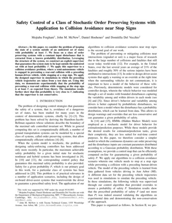
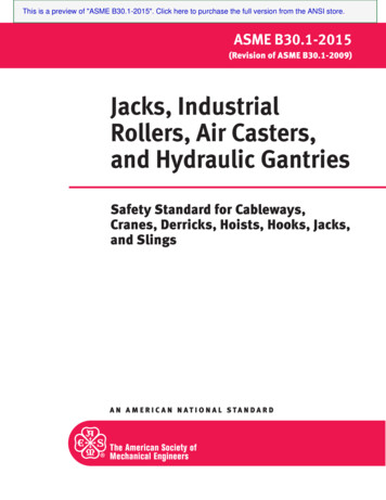
Safety Standard ISO13849-1Under EN ISO 13849-1, the consideration of safety starts with the risks associated with the machine, its function and its operation.Machine designers are obliged to eliminate risks before considering further measures to reduce or control risks (EN ISO 12100).The risks of the machine must be quantified by the machine designer and if the risks are considered high, the designer is obligedto employ systems that reduce the risks to acceptable levels. Once the risks have been reduced to acceptable levels by means ofan inherent safe design, then protective devices will be required. At that point, safety functions (SF) must be defined and satisfiedby the machine design.EN ISO13849-1 uses an interactive process for the design of the safety-related parts of control systems, as follows:For each SFFrom risk analysis(EN ISO 12100)1Identification of safety functions (SF)2Specification of characteristics of each SF3Determination of required PL (PLr)4Realisation of SF, identification of SRP/CS5Evaluation of PL for SPR/CS consideringcategory, MTTFd, DCavg, CCF6Verification:PL PLr?noSF safety functionPL performance levelPLr required performance levelSRP/CS safety-related parts of control systemsMTTFd mean time of dangerous failureDCavg average diagnostic coverageCCF common cause failureyes7Validation:requirements met?noyes8To risk analysis(EN ISO 12100)All SFanalysed?noyes A required performance level “PLr” (target value) must be specified for each intended safety function. The safety function requirements are derived from the necessary risk reduction. ISO/TR 14121-2 describes methods for determining the necessary level of risk reduction. EN ISO 13849-1 employs one of these methods where the following parameters are evaluated:S – Severity of injuryF – Frequency and time of exposure to the hazardP – Possibility of avoiding the hazard or limiting the harm.3
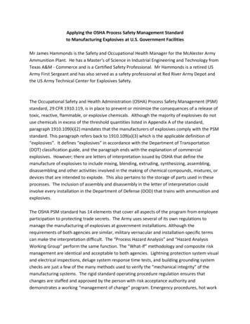
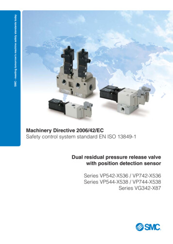
Following the standardDetermination of Required Performance Level PLrThere are five performance levels: a, b, c, d, e, with “a” being low risk and “e” representing the highest risk.Each of these five performance levels corresponds to a further parameter scale, based on the probability of a dangerous failureper hour.P1S: Severity of InjuryS1: slightS2: seriousaF1F: Frequency and/or exposure to the hazardF1: no oftenF2: frequentP2S1bP1F2StartP2P1cP: Possibility of avoiding the hazard or limiting harmP1: possibleP2: scarcely possibledPL defined statisticallyF1P2S2P1F2PLP2eabcdeLevel of riskAverage probability ofdangerous failures per hour, h-1 10-5 to 10-4 3 x 10⁻⁶ to 10-5 10-6 to 3 x 10⁻⁶ 10-7 to 10-6 10-8 to 10-7Once the safety function (SF) and the required risk reduction PLr have been defined, the actual design of the SRP/CS can begin as suitable protective measures have to be used to match the performance levels.Determination of Performance Level PLThe following elements define the performance level or PL:1. The architecture categories of the safety system2. The reliability of the safety system (MTTFd)3. How easily faults can be detected (DCavg)4. How vulnerable the system is to failure (CCF)Once the design of the safety control systems has been completed and the PLs have been determined, a verification andvalidation process should be completed in accordance with EN ISO13849-2.Architecture categories of the safety systemThe architecture categories help to classify the safety-related parts of a control system (SRP/CS) in relation to their resistance tofaults and their subsequent behaviour in the fault condition, based upon the reliability and/or the structural arrangement of the parts.For defining the probability of failure and the PL, the architecture categories provide the major definition, completed by thecomponent reliability (MTTFd), the diagnostic coverage (DCavg), and the resistance to common cause failures (CCF) information.There are five architecture categories: B, 1, 2, 3, 4.Architectural complexity of a systemBLowLow1ab23cdPerformance44eHighHigh
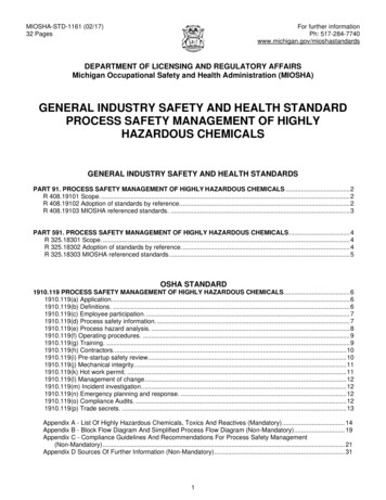
Architecture categories – B and 1In categories B and 1, the resistance to faults is achieved primarily by the selection and use of suitable components.Category 1 has a greater resistance than category B because of the use of basic and well-tried principles, as well as well-triedcomponents, wich are tested in a safety context.A typical application: – 24VThe simple sytem to remove supply pressure possibly suitablefor low risk application which is PL 'a'1112Input(A)2S1Logic/processingOutputSystem1 3(P) (R)GNDArchitecture – category 2Category 2 combines all of the requirements of architecture B with well-tried safety principles. Additionally the system is checkedfor faults affecting the safety function.These checks are made at regular intervals, e.g. at start-up, or before the next demand on the safety function. By using anappropriate selection of test intervals, a suitable risk reduction can be attained.Input signalOutput signalLOTEOTEImArchitecture categories – 3 and 4In categories 3 and 4, the occurrence of a single fault does not result in the loss of the safety function.In category 4, and whenever reasonably practical in category 3, such faults are detected automatically.In category 4, accumulation of faults will not lead to a loss of the safety function.System for use with SMC Products:mL1I1Control inputsO1Input signalOutput signalInput signalCSuitable safety controller/relayOutput signalmI2Input signalL2O2Monitor signalOutput signalm: monitoring of output statec: cross monitoring of logic channels2 protected systemAir supply 133Channel 1Channel 2SMC special product - in this example the product being tested is our series VG342(R)-첸-X87.5
Reliability of a safety systemThe reliability of a system has to be quantified as part of the Performance level (PL).Reliability is expressed as the Mean Time to Dangerous Failure (MTTFd ) which is measured in hours. The MTTFd should bedetermined from the component manufacturer’s data.However, as this is application-specific, the components MTTFd cannot be quoted in isolation as the manufacturer is not aware ofthe exact machine application.As the world leading experts in pneumatics we will provide estimated MTTF or B10 values, to help support our customers.However, we (SMC) will not accept liability for the use of these components in safety systems beyond our normalwarranty terms.MTTF or B10 are defined respectively as mean time to failure or number of cycles until 10% of the components has exceededfixed limits under defined conditions, such as response time, leakage, or switching pressure.Finding the MTTFd - Value of a pneumatic component with B10 - Value according to EN ISO 13849-1Input parameter: B10: Number of cycles, until 10% of the components fails hOP: Mean operation [hours/day] TCycle: Mean time between the beginning of two successive cycles of the component [s/cycle]Output parameter: nOP: Mean number of annual operations B10d: Number of cycles, until 10% of the components fails dangerously MTTFd: Mean time to dangerous failureTypical procedure (in certain circumstances):B10 d 2 x B10nOP dOP x hOP x 3600[s/h]MTTFd TCycleB10d0.1 x nOPFinding the MTTFd - Value of a component which combines both electronic and pneumatic partsThe dependency of the probability of failure related to time (electronic) as well as cycles (pneumatic component) is an indication of such acombined system (combined fluid and electric systems).The total MTTFd - value of the combined system will be determined from the B10d value of the pneumatic component and the MTTFd - value ofthe electronic components.In case of a valve, the tested B10 valve represents the mechanical and the electrical part of the valve.Diagnostic CoverageA factor called DC (Diagnostic Coverage) is a measure of how effectively failures can be detected by monitoring systems.Sensors can be used to detect faults when monitored by a logic / processing device.EN ISO 13849-1 provides the means of estimating DC which is then used as part of the determination of PL.Diagnostic Coverage is defined as the measure of the effectiveness of diagnostics, which may be determined as the ratiobetween the failure rate of detected dangerous failures and the failure rate of total dangerous failures; so 0% no dangerousfaults are detected and approaching 100% most faults detected (but 100% is impossible because diagnostics are notconsidered to be completely reliable).6
Diagnostic coverage categories:CategoryNoneLowMediumHighRangeDC 60%60% DC 90%90% DC 99%99% DCDiagnostic coverage estimates (for output devices such as SMC valves with position detection):MeasureDiagnostic coverageMonitoring of outputs by one channel without dynamic test.0% to 99% depending on how often a signal change is done by the application.Cross monitoring of outputs without dynamic test.0% to 99% depending on how often a signal change is done by the application.Cross monitoring of output signals with dynamic test withoutdetection of short circuits (for multiple I/O)90%Cross monitoring of output signals and intermediate resultswithin the logic and temporal and logical software monitor of theprogram flow and detection of static faults and short circuits (formultiple I/O)99%Redundant shut-off path with no monitoring of the actuator0%Redundant shut-off with monitoring of one of the actuators either90%by logic or by test equipmentRedundant shut-off path with monitoring of the actuators bylogic and test equipment99%Indirect monitoring (e.g. monitoring by pressure switch,electrical position monitoring of actuators)90% to 99%, depending on the applicationFault detection by the process0% to 99%, depending on the application; this measure alone is not sufficientfor the required performance level ‘e’Direct monitoring (e.g. electrical position monitoring of controlvalves, monitoring of electromechanical devices by mechanically linked contact elements)99%Common Cause FailureIt is necessary to consider how single failures might affect safety systems when there is redundancy in the system.Redundancy can be compromised if both channels fail simultaneously due to the same cause. This factor is called CCF(Common Cause Failure).EN ISO 13849-1 provides a score for CCF, which is used to determine the Performance level PL.For this score, EN ISO13849-1 defines a checklist of eight important countermeasures, which are evaluated as follows: Physical separation between the signal paths of different channels (15 points) Diversity in the technology, the design or the physical principles of the channels (20 points) Protection against possible overloading (15 points) and the use of well-tried components (5 points) Failure mode and effects analysis during development for the identification of potential common cause failures (5 points) Training of designer/maintainers in CCF and its avoidance (5 points) Protection against common cause failures triggered by contamination (mechanical and fluidic system) and electromagneticinterference (electrical system) (25 points) Protection about common cause failures triggered by unfavourable environmental conditions (10 points)A maximum sc
ISO/TR 14121-2 describes methods for determining the necessary level of risk reduction. EN ISO 13849-1 employs one of these methods where the following parameters are evaluated: S – Severity of injury F – Frequency and time of exposure to the hazard P – Possibility of avoiding the hazard or limiting the harm. Safety Standard ISO13849-1