Transcription
Embedded Memory (RAM: 1-PORT,RAM: 2-PORT, ROM: 1-PORT, andROM: 2-PORT) User GuideUpdated for Intel Quartus Prime Design Suite: 17.0SubscribeSend FeedbackUG-01068 2017.11.06Latest document on the web: PDF HTML
ContentsContents1 About Embedded Memory IP Cores. 31.1 Features.32 Embedded Memory IP Cores Getting Started. 42.1 Changing Parameter Settings Manually. 42.2 Parameter Settings. 53 Functional Description. 83.1 Memory Block Types. 83.2 Write and Read Operations Triggering.93.3 Port Width Configurations. 113.4 Mixed-width Port Configuration. 123.5 Mixed-width Ratio Configuration.123.6 Maximum Block Depth Configuration. 123.7 Clocking Modes and Clock Enable. 133.8 Memory Blocks Address Clock Enable Support.143.9 Byte Enable . 163.10 Asynchronous Clear.173.11 Read Enable. 183.12 Read-During-Write. 193.12.1 Selecting RDW Output Choices for Various Memory Blocks. 193.13 Power-Up Conditions and Memory Initialization. 213.14 Error Correction Code . 223.15 Freeze Logic. 224 Parameters and Signals. 244.14.24.34.44.5RAM:1-Port IP Core Parameters. 24RAM: 2-Port IP Core Parameters. 26ROM: 1-PORT IP Core Parameters. 31ROM: 2-PORT IP Core Parameters. 33Signals. 355 Design Example. 395.1 External ECC Implementation with True-Dual-Port RAM. 395.1.1 Generating the ALTECC ENCODER and ALTECC DECODER with the RAM:2-PORT IP Core.405.1.2 Simulating the Design. 42A Document Revision History for Embedded Memory (RAM: 1-PORT, RAM: 2-PORT,ROM: 1-PORT, and ROM: 2-PORT) User Guide. 47Embedded Memory (RAM: 1-PORT, RAM: 2-PORT, ROM: 1-PORT, and ROM: 2-PORT) User Guide2
UG-01068 2017.11.061 About Embedded Memory IP CoresThe Intel Quartus Prime software offers several IP cores to implement memorymodes. The available IP cores depend on the target device. You can access thefeatures of the Embedded Memory using the On-Chip Memory IP cores in the IntelQuartus Prime software.1.1 FeaturesTable 1.Memory IP Cores and Their FeaturesMemory IPRAM: 1-PORTSupported MemoryMode Non-simultaneous read and write operations from a single address.Read enable port to specify the behavior of the RAM output ports duringa write operation, to overwrite or retain existing value.Supports freeze logic feature.Simple dual-port RAM Simultaneous one read and one write operations to different locations.Supports error correction code (ECC).Supports freeze logic feature.True dual-port RAM Simultaneous two reads.Simultaneous two writes.Simulatenous one read and one write at two different clock frequencies.Supports freeze logic feature.ROM: 1-PORTSingle-port ROM One port for read-only operations.Initialization using a .mif or .hex file.ROM: 2-PORTDual-port ROM Two ports for read-only operations.Initialization using a .mif or .hex file.RAM: 2-PORTSingle-port RAMFeatures Intel Corporation. All rights reserved. Intel, the Intel logo, Altera, Arria, Cyclone, Enpirion, MAX, Nios, Quartusand Stratix words and logos are trademarks of Intel Corporation or its subsidiaries in the U.S. and/or othercountries. Intel warrants performance of its FPGA and semiconductor products to current specifications inaccordance with Intel's standard warranty, but reserves the right to make changes to any products and servicesat any time without notice. Intel assumes no responsibility or liability arising out of the application or use of anyinformation, product, or service described herein except as expressly agreed to in writing by Intel. Intelcustomers are advised to obtain the latest version of device specifications before relying on any publishedinformation and before placing orders for products or services.*Other names and brands may be claimed as the property of others.ISO9001:2008Registered
UG-01068 2017.11.062 Embedded Memory IP Cores Getting StartedThis chapter provides a general overview of the Intel FPGA IP core design flow to helpyou quickly get started with the Embedded Memory IP cores. The Intel FPGA IP Libraryis installed as part of the Intel Quartus Prime software installation process. You canselect and parameterize any Intel FPGA IP core from the library. Intel provides anintegrated parameter editor that allows you to customize the Embedded Memory IPcores to support a wide variety of applications. The parameter editor guides youthrough the setting of parameter values and selection of optional ports.Related Links Introduction to Intel FPGA IP CoresProvides general information about all Intel FPGA IP cores, includingparameterizing, generating, upgrading, and simulating IP cores. Creating Version-Independent IP and Qsys Simulation ScriptsCreate simulation scripts that do not require manual updates for software or IPversion upgrades. Project Management Best PracticesGuidelines for efficient management and portability of your project and IP files.2.1 Changing Parameter Settings ManuallyWhen the IP core has been generated using the IP Parameter Editor, you can use thisflow to change of the parameter settings within the specified memory mode. However,to change the memory mode, use the IP Parameter Editor to configure and regeneratethe IP core.Follow these steps to change the parameter settings manually:1.Locate the Verilog design file: project directory / project name softwareversion /synth/ project name rtl .v.2.Change the parameter settings in the design file. Ensure that you use only legalparameter values as specified in Parameters and Signals topic. Failing to do soresults in compilation errors.3.Compile the design using the Intel Quartus Prime software.For example, the following codes enable the ECC feature and specify the initializationfile.altera syncram component.enable ecc "TRUE",altera syncram component.ecc pipeline stage enabled "FALSE",altera syncram component.init file "mif1.mif",Intel Corporation. All rights reserved. Intel, the Intel logo, Altera, Arria, Cyclone, Enpirion, MAX, Nios, Quartusand Stratix words and logos are trademarks of Intel Corporation or its subsidiaries in the U.S. and/or othercountries. Intel warrants performance of its FPGA and semiconductor products to current specifications inaccordance with Intel's standard warranty, but reserves the right to make changes to any products and servicesat any time without notice. Intel assumes no responsibility or liability arising out of the application or use of anyinformation, product, or service described herein except as expressly agreed to in writing by Intel. Intelcustomers are advised to obtain the latest version of device specifications before relying on any publishedinformation and before placing orders for products or services.*Other names and brands may be claimed as the property of others.ISO9001:2008Registered
2 Embedded Memory IP Cores Getting StartedUG-01068 2017.11.06To disable the ECC feature and specify a different .mif file, make the followingchanges.altera syncram component.enable ecc "FALSE",altera syncram component.ecc pipeline stage enabled "FALSE",altera syncram component.init file "mif2.mif",Related LinksParameters and Signals on page 242.2 Parameter SettingsTable 3.Parameters for altera syncramUse the parameter list when editing the design file manually.Nameoperation modeLegal ValuesSINGLE PORTDUAL PORTBIDIR DUAL PORTROMDescriptionOperation mode of the memory block.width a—Data width of port A.widthad a—Address width of port A.numwords a—Number of data words in the memory block forport A.outdata reg aUNREGISTEREDCLOCK1CLOCK0Clock for the data output registers of port A.outdata aclr aNONECLEAR1CLEAR0Asynchronous clear for data output registers ofport A. When the outdata reg a parameteris set to UNREGISTERED, this parameterspecifies the clearing parameter for the outputlatch.address aclr aNONECLEAR0Option to clear the address input registers ofport A.width byteena a—Width of the byte-enable bus of port A. Thewidth must be equal to the value of width adivided by the byte size. The default value of 1is only allowed when byte-enable is not used.width b—Data width of port B.widthad b—Address width of port B.numwords b—Number of data words in the memory block forport B.outdata reg bUNREGISTEREDCLOCK1CLOCK0Clock for the data output registers of port B.indata reg bCLOCK1CLOCK0Clock for the data input registers of port B.address reg bCLOCK1CLOCK0Clock for the address registers of port B.continued.Embedded Memory (RAM: 1-PORT, RAM: 2-PORT, ROM: 1-PORT, and ROM: 2-PORT) User Guide5
2 Embedded Memory IP Cores Getting StartedUG-01068 2017.11.06NameLegal ValuesDescriptionbyteena reg bCLOCK1CLOCK0Clock for the byte-enable registers of port B.outdata aclr bNONECLEAR1CLEAR0Asynchronous clear for data output registers ofport B. When the outdata reg b parameteris set to UNREGISTERED, this parameterspecifies the clearing parameter for the outputlatch.address aclr bNONECLEAR0Option to clear the address input registers ofport B.width byteena bram block typebyte sizeread during write mode mixedportsinit fileinit file layoutmaximum depthclock enable input aclock enable output a—M20KMLABAUTO58910DONT CARECONSTRAINT DONT CARENEW DATAOLD DATA—PORT APORT B—NORMALBYPASSALTERNATENORMALBYPASSWidth of the byte-enable bus of port B. Thewidth must be equal to the value of width bdivided by the byte size. The default value of 1is only allowed when byte-enable is not used.The memory block type.The byte size for the byte-enable mode.The behavior for the read-during-write mode. The default value is DONT CARE. The value of NEW DATA is supported onlywhen the read address and output data areregistered by the write clock in the LUTRAMmode. The value of CONSTRAINED DONT CAREis supported only in the LUTRAM mode.The initialization file.The layout of the initialization file.The depth of the memory block slices.The clock enable for the input registers of portA.The clock enable for the output registers of portA.clock enable core aNORMALBYPASSALTERNATEThe clock enable for the core of port A.clock enable input bNORMALBYPASSALTERNATEThe clock enable for the input registers of portB.clock enable output bclock enable core bNORMALBYPASSNORMALBYPASSALTERNATEThe clock enable for the output registers of portB.The clock enable for the core of port A.continued.Embedded Memory (RAM: 1-PORT, RAM: 2-PORT, ROM: 1-PORT, and ROM: 2-PORT) User Guide6
2 Embedded Memory IP Cores Getting StartedUG-01068 2017.11.06NameLegal Valuesread during write mode port aNEW DATA NO NBE READNEW DATA WITH NBE READOLD DATADONT CAREThe read-during-write behavior for port A.read during write mode port bNEW DATA NO NBE READNEW DATA WITH NBE READOLD DATADONT CAREThe read-during-write behavior for port B.enable eccwidth eccstatusDescriptionTRUEFALSEEnables or disables the ECC feature.2The width of the eccstatus signal.Embedded Memory (RAM: 1-PORT, RAM: 2-PORT, ROM: 1-PORT, and ROM: 2-PORT) User Guide7
UG-01068 2017.11.063 Functional DescriptionDescribes the features and functionality of the embedded memory blocks and theports of the RAM: 1-PORT, RAM: 2-PORT, ROM: 1-PORT, and ROM: 2-PORT IP cores.3.1 Memory Block TypesIntel provides various sizes of embedded memory blocks for various devices.The parameter editor allows you to implement your memory in the following ways: Select the type of memory blocks available based on your target device. To selectthe appropriate memory block type for your device, obtain more information aboutthe features of your selected embedded memory block in your target device, suchas the maximum performance, supported configurations (depth width), byteenable, power-up condition, and the write and read operation triggering. Use logic cells. As compared to embedded memory resources, using logic cells tocreate memory reduces the design performance and utilizes more area. Thisimplementation is normally used when you have used up all the embeddedmemory resources. When logic cells are used, the parameter editor provides youwith the following two types of logic cell implementations: Note:—Default logic cell style—the write operation triggers (internally) on the risingedge of the write clock and have continuous read. This implementation usesless logic cells and is faster, but it is not fully compatible with the Stratix M512 emulation style.—Stratix M512 emulation logic cell style—the write operation triggers(internally) on the falling edge of the write clock and performs read only onthe rising edge of the read clock.Select the Auto option, which allows the software to automatically select theappropriate embedded memory resource. When you set the memory block type toAuto, the compiler favors larger block types that can support the memorycapacity you require in a single embedded memory block. This setting gives thebest performance and requires no logic elements (LEs) for glue logic. When youcreate the memory with specific embedded memory blocks, such as M9K, thecompiler is still able to emulate wider and deeper memories than the block typesupported natively. The compiler spans multiple embedded memory blocks (onlyof the same type) with glue logic added in the LEs as needed.To obtain proper implementation based on the memory configuration you set, allowthe Intel Quartus Prime software to automatically choose the memory type. This givesthe compiler the flexibility to place the memory function in any available memoryresources based on the functionality and size.Intel Corporation. All rights reserved. Intel, the Intel logo, Altera, Arria, Cyclone, Enpirion, MAX, Nios, Quartusand Stratix words and logos are trademarks of Intel Corporation or its subsidiaries in the U.S. and/or othercountries. Intel warrants performance of its FPGA and semiconductor products to current specifications inaccordance with Intel's standard warranty, but reserves the right to make changes to any products and servicesat any time without notice. Intel assumes no responsibility or liability arising out of the application or use of anyinformation, product, or service described herein except as expressly agreed to in writing by Intel. Intelcustomers are advised to obtain the latest version of device specifications before relying on any publishedinformation and before placing orders for products or services.*Other names and brands may be claimed as the property of others.ISO9001:2008Registered
3 Functional DescriptionUG-01068 2017.11.06Table 4.Embedded Memory Blocks in Intel FPGA DevicesDevice FamilyMemory Block TypeMLAB (640bits)M9K (9 Kbits)M144K (144Kbits)M10K (10 Kbits)M20K (20Kbits)Logic Cell(LC)Arria II GXYesYes–––YesArria II GZYesYesYes––YesArria VYes––Yes–YesIntel Arria 10Yes–––YesYesCyclone IV–Yes–––YesYes––Yes–YesIntel Cyclone10 LP–Yes–––YesIntel Cyclone10 GXYes–––YesYesMAX II–––––YesIntel MAX 10–Yes–––YesStratix IVYesYesYes––YesStratix VYes–––YesYesCyclone VNote:To identify the type of memory block that the software selects to create your memory,refer to the Fitter report after compilation.3.2 Write and Read Operations TriggeringThe embedded memory blocks vary slightly in its supported features and behaviors.One important variation is the difference in the write and read operations triggering.Table 5.Write and Read Operations Triggering for Embedded Memory BlocksThis table lists the write and read operations triggering for various embedded memory blocks.Write OperationRead OperationM10KRising clock edgesRising clock edgesM20KRising clock edgesRising clock edgesM144KRising clock edgesRising clock edgesM9KRising clock edgesRising clock edgesEmbedded MemoryBlockscontinued.(1)MLAB blocks are not supported in simple dual-port RAM mode with mixed-width port feature,true dual-port RAM mode, and dual-port ROM mode.(2)Write operation triggering is not applicable to ROMs.Embedded Memory (RAM: 1-PORT, RAM: 2-PORT, ROM: 1-PORT, and ROM: 2-PORT) User Guide9
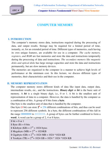
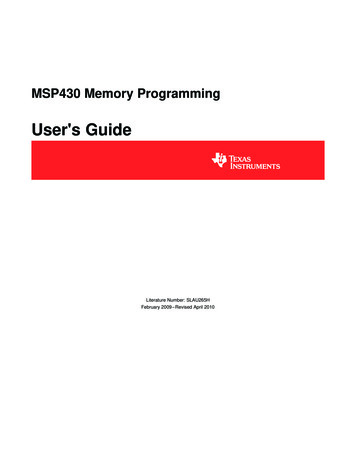
3 Functional DescriptionUG-01068 2017.11.06Embedded MemoryBlocksWrite OperationRead OperationRising clock edges(3)MLABFalling clock edgesRising clock edges (in Intel Arria 10, ArriaV, Cyclone V, and Stratix V devices only)M-RAMRising clock edgesRising clock edgesM4KFalling clock edgesRising clock edgesM512Falling clock edgesRising clock edgesIt is important that you understand the write operation triggering to avoid potentialwrite contentions that can result in unknown data storage at that location.These figures show the valid write operation that triggers at the rising and falling clockedge, respectively.Figure 1.Valid Write Operation that Triggers at Rising Clock EdgesThis figure assumes that twc is the maximum write cycle time interval. Write operation of data 03 through portB does not meet the criteria and causes write contention with the write operation at port A, which result inunknown data at address 01. The write operation at the next rising edge is valid because it meets the criteriaand data 04 replaces the unknown data.clock aaddress a01wren adata a0605twcValid Writeclock baddress b01wren bdata b02030405(3)MLAB supports continuos reads. For example, when you write a data at the write clock risingedge and after the write operation is complete, you see the written data at the output portwithout the need for a read clock rising edge.(2)Write operation triggering is not applicable to ROMs.Embedded Memory (RAM: 1-PORT, RAM: 2-PORT, ROM: 1-PORT, and ROM: 2-PORT) User Guide10
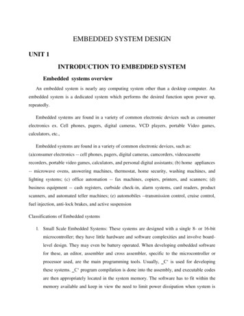
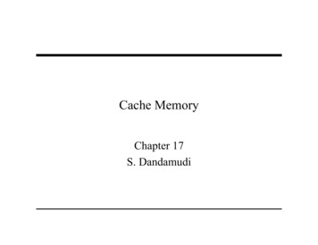
3 Functional DescriptionUG-01068 2017.11.06Figure 2.Valid Write Operation that Triggers at Falling Clock EdgesThis figure assumes that twc is the maximum write cycle time interval. Write operation of data 04 through portB does not meet the criteria and therefore causes write contention with the write operation at port A that resultin unknown data at address 01. The next data (05) is latched at the next rising clock edge that meets thecriteria and is written into the memory block at the falling clock edge.clock aaddress a01wren adata a0605twc Valid Write Actual Writeclock baddress b01wren bdata bNote:02030405Data and addresses are latched at the rising edge of the write clock regardless of thedifferent write operation triggering.3.3 Port Width ConfigurationsThe following equation defines the port width configuration: Memory depth (number ofwords) Width of the data input bus.(2) If your port width configuration (either the depth or the width) is more than theamount an internal memory block can support, additional memory blocks (of thesame type) are used. For example, if you configure your M9K as 512 36, whichexceeds the supported port width of 512 18, two M9Ks are used to implementyour RAM. In addition to the supported configuration provided, you can set the memorydepth to a non-power of two, but the actual memory depth allocated can vary. Thevariation depends on the type of resource implemented. If the memory is implemented in dedicated memory blocks, setting a non-powerof two for the memory depth reflects the actual memory depth. When you implement your memory using dedicated memory blocks, refer to theFitter report to check the actual memory depth.Write operation triggering is not applicable to ROMs.Embedded Memory (RAM: 1-PORT, RAM: 2-PORT, ROM: 1-PORT, and ROM: 2-PORT) User Guide11
3 Functional DescriptionUG-01068 2017.11.063.4 Mixed-width Port ConfigurationOnly dual-port RAM and dual-port ROM support mixed-width port configuration for allmemory block types except when they are implemented with LEs. The support formixed-width port depends on the width ratio between port A and port B. In addition,the supporting ratio varies for various memory modes, memory blocks, and targetdevices.Note:MLABs do not have native support for mixed-width operation, thus the option to selectMLABs is disabled in the parameter editor. However, the Intel Quartus Prime softwarecan implement mixed-width memories in MLABs by using more than one MLAB.Therefore, if you select AUTO for your memory block type, it is possible to implementmixed-width port memory using multiple MLABs.Memory depth of 1 word is not supported in simple dual-port and true dual-port RAMswith mixed-width port. The parameter editor prompts an error message when thememory depth is less than 2 words. For example, if the width for port A is 4 bits andthe width for port B is 8 bits, the smallest depth supported by the RAM is 4 words.This configuration results in memory size of 16 bits (4 4) and can be represented bymemory depth of 2 words for port B. If you set the memory depth to 2 words thatresults in memory size of 8 bits (2 4), it can only be represented by memory depthof 1 word for port B, and therefore the width of the port is not supported.3.5 Mixed-width Ratio ConfigurationTable 6.Supported Mixed-Width Ratio Configurations for Intel Arria 10Operation ModeMixed-width RatioWithout Byte EnableWith Byte EnableSimple dual-port1, 2, 4, 8, 16, and 321, 2, and 4True dual-port1, 2, 4, 8, and 161 and 2Simple quad-portNot supportedNot supported3.6 Maximum Block Depth ConfigurationYou can limit the maximum block depth of the dedicated memory block you use.The memory block can be sliced to your desired maximum block depth. For example,the capacity of an M9K block is 9,216 bits, and the default memory depth is 8K, inwhich each address is capable of storing 1 bit (8K 1). If you set the maximum blockdepth to 512, the M9K block is sliced to a depth of 512 and each address is capable ofstoring up to 18 bits (512 18).You can use this option to save power usage in your devices. However, this parametermight increase the number of LEs and affects the design performance.When the RAM is sliced shallower, the dynamic power usage decreases. However, for aRAM block with a depth of 256, the power used by the extra LEs starts to outweighthe power gain achieved by shallower slices.Embedded Memory (RAM: 1-PORT, RAM: 2-PORT, ROM: 1-PORT, and ROM: 2-PORT) User Guide12
3 Functional DescriptionUG-01068 2017.11.06You can also use this option to reduce the total number of memory blocks used (but atthe expense of LEs). The 8K 36 RAM uses 36 M9K RAM blocks with a default slicingof 8K 1. By setting the maximum block depth to 1K, the 8K 36 RAM can fit into 32M9K blocks.The maximum block depth must be in a power of two, and the valid values varyamong different dedicated memory blocks.Table 7.Valid Range of Maximum Block Depth for Various Embedded Memory BlocksEmbedded Memory BlocksValid �64KThe parameter editor prompts an error message if you enter an invalid value for themaximum block depth. Intel recommends that you set the value to Auto if you arenot sure of the appropriate maximum block depth to set or the setting is notimportant for your design. This setting enables the compiler to select the maximumblock depth with the appropriate port width configuration for the type of embeddedmemory block of your memory.3.7 Clocking Modes and Clock EnableThe embedded memory block supports various types of clocking modes depending onthe memory mode you select.Table 8.Clocking ModesClocking ModesDescriptionSingle Clock ModeIn the single clock mode, a single clock, together with a clock enable, controls all registers of thememory block.Read/Write ClockModeIn the read/write clock mode, a separate clock is available for each read and write port. A read clockcontrols the data-output, read-address, and read-enable registers. A write clock controls the datainput, write-address, write-enable, and byte enable registers.Input/Output ClockModeIn input/output clock mode, a separate clock is available for each input and output port. An inputclock controls all registers related to the data input to the memory block including data, address,byte enables, read enables, and write enables. An output clock controls the data output registers.Independent ClockModeIn the independent clock mode, a separate clock is available for each port (A and B). Clock A controlsall registers on the port A side; clock B controls all registers on the port B side.continued.(4)The maximum block depth must be in a power of two.(5)The maximum block depth setting (64) for MLAB is not available for Arria V and Cyclone Vdevices.Embedded Memory (RAM: 1-PORT, RAM: 2-PORT, ROM: 1-PORT, and ROM: 2-PORT) User Guide13
3 Functional DescriptionUG-01068 2017.11.06Clocking ModesDescriptionNote: You can create independent clock enable for different input and output registers to control theshut down of a particular register for power saving purposes. From the parameter editor, clickMore Options (beside the clock enable option) to set the available independent clock enablethat you prefer.Table 9.Clocking ModesThis table lists the embedded memory clocking modes.Clocking ModesSingle-port RAMSimple Dual-portRAMTrue Dual-portRAMSingle-port ROMDual-port ROMSingle ��—Supported—SupportedNote:Asynchronous clock mode is only supported in MAX series of devices, and notsupported in Stratix and newer devices. However, newer devices supportasynchronous read memory for simple dual-port RAM mode if you choose MLABmemory block with unregistered rdaddress port.Note:The clock enable signals are not supported for write address, byte enable, and datainput registers on Arria V, Cyclone V, and Stratix V MLAB blocks.3.8 Memory Blocks Address Clock Enable SupportThe embedded memory blocks support address clock enable, which holds the previousaddress value for as long as the signal is enabled (addressstall 1). When thememory blocks are configured in dual-port mode, each port has its own independentaddress clock enable. The default value for the address clock enable signal is low(disabled).Embedded Memory (RAM: 1-PORT, RAM: 2-PORT, ROM: 1-PORT, and ROM: 2-PORT) User Guide14
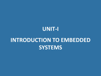
3 Functional DescriptionUG-01068 2017.11.06Figure 3.Address Clock EnableThis figure shows an address clock enable block diagram. The address clock enable is referred to by the portname stallclockFigure 4.Address Clock Enable During Read Cycle WaveformThis figure shows the address clock enable waveform during the read lllatched address(inside memory)anq (synch) doutn-1q 5dout4dout5Embedded Memory (RAM: 1-PORT, RAM: 2-PORT, ROM: 1-PORT, and ROM: 2-PORT) User Guide15
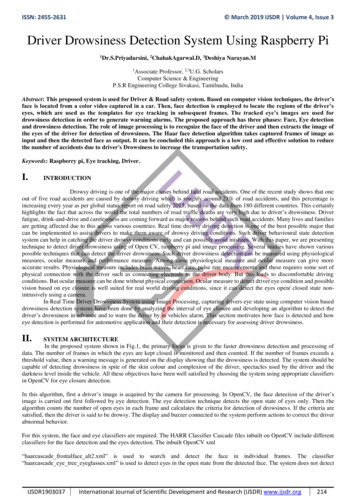
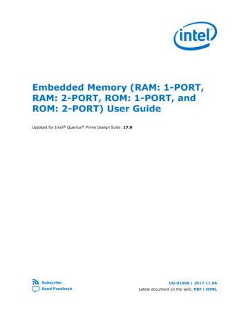
3 Functional DescriptionUG-01068 2017.11.06Figure 5.Address Clock Enable During the Write Cycle WaveformThis figure shows the address clock enable waveform during the write 0506wrenaddressstalllatched address(inside memory)contents at a0contents at a1ana1a0XX0102XXcontents at a3XXcontents at a5a500XXcontents at a2contents at a4a40304XXXX053.9 Byte EnableAll embedded memory blocks that are implemented as RAMs support byte enablesthat mask the input data so that only specific bytes, nibbles, or bits of data arewritten. The unwritten bytes or bits retain the previously written value.The LSB of the byte-enable port corresponds to the LSB of the data bus. For example,if you use a RAM block in x18 mode and the byte-enable port is 01, data [8.0] isenabled and data [17.9] is disabled. Similarl
1 About Embedded Memory IP Cores The Intel Quartus Prime software offers several IP cores to implement memory modes. The available IP cores depend on the target device. You can access the features of the Embedded Memory using the On-Chip Memory IP cores in the Intel Quartus Prime software. 1.1 Features Table 1. Memory IP Cores and Their Features