Transcription
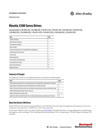
RAM 100 1000 5500RAMSETwww.ramsetinc.com
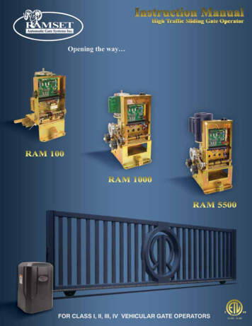
RAMSETTABLE OF CONTENTSResponsibilities of Installers and Technicians.2Important Safety Requirements by UL Standards.3Classes of Vehicular Gate Operators.4General Specifications.5RAM 100 Installation Specifications.6RAM 100 Front Installation/ Foot Pedal Release.7RAM 1000/ RAM 5500 Installation Specifications.8RAM 1000/ RAM 5500 Types of Installations.9Loop Sensor Installation/ Gate Travel Adjustment.10Pushbutton Controls & Master/Slave Installation.11Dip Switch Configuration. 12-13Terminal Strip Connections. 14-15Ramset “Intelligate” Control Board.16Wire Board Connections.17RAM 100 Parts Diagram.18RAM 1000/ RAM 5500 Parts Diagram.19Bill of Materials. 20-21Gate Entrance Safety Precautions.22Important Information for the Homeowner.23Troubleshooting Table.24WARNINGDo not install this gate operator if you do not have experience or appropriatetraining with gate operators.IMPORTANT SAFETY REQUIREMENTS & INSTRUCTIONSWARNING To reduce the risk of injury or death:1.READ AND FOLLOW ALL INSTRUCTIONS.2.Never let children operate or play with gate controls.Keep the remote control away from children.3.Always keep people and objects away from the gate.4.Test the Vehicular Gate Operator monthly. The gateMUST reverse on contact with a rigid object or stopwhen an object activates the non-contact sensors.After adjusting the limit of travel, retest the VehicularGate Operator. Failure to adjust and retest theNO ONE SHOULD CROSS THE PATH OF THE MOVINGGATE.Vehicular Gate Operator properly can increase therisk of injury or death.5.Use the Emergency Release only when power switchor circuit breaker has been turned off. Using the Emergency Release during a power failure can be a hazardif power is abruptly restored.6.KEEP GATES PROPERLY MAINTAINED. Read theOwner’s Manual. Have a qualified service personmake repairs to gate hardware.7. The entrance is for vehicles only. Pedestrians mustuse separate entrance.8.SAVE THESE INSTRUCTIONS.www.ramsetinc.com1RAM 100 1000 5500Important Safety Requirements & Instructions.1
RAMSETResponsibilities of installers and techniciansRAM 100 1000 5500installation Read and understand the instruction manual before attemptingany installation. Do not exceed the equipment specifications. Insure a safe and proper installation. Install this equipment in accordance with the Ul 325 specifications. Make sure to eliminate any pinch points existing on the installation.(ie. Rollers, arms etc. ) ramset gate operators must be installed by a trained technician.Safety devices Remove or protect all pinch points from the gate operator. Make sure every installation has a minimum of one non-contactsafety device (such as a photo eye or loop detector). Check the e.r.d. Sensitivity for proper adjustments. Make sure that all areas around the gate are safe and secure.(such as the front, rear, and travel area).Communicate with the end-user Instruct the end user on how to safely operate all functionsof the operator. Instruct the end-user on how to safely use the emergencyrelease. Clearly label and identify the circuit breaker for the operator. Show the end-user the location of the circuit breaker for theoperator. Thoroughly explain any and all warranties associated with theoperator and installation. Keep a copy of each manual handy for future references. Provide the end-user with the “home owners manual packet”(included with every operator).2www.ramsetinc.com
RAMSET rior to installation, the following must bePobserved: (per UL 325.56.8.4).a) Install the gate operator only when:1. The operator is appropriate for the construction ofthe gate and the usage Class of the gate,2. All openings of a horizontal slide gate are guardedor screened from the bottom of the gate to a minimum of 4 feet (1.22 m) above the ground to preventa 2 1/4 inch (57.2 mm) diameter sphere from passingthrough the openings anywhere in the gate, and inthat portion of the adjacent fence that the gate coversin the open position.3. All exposed pinch points are eliminated or guarded,and4. Guarding is supplied for exposed rollers.b) The operator is intended for installation only on gatesused for vehicles. Pedestrians must be supplied with aseparate access opening. The pedestrian access openingshall be designed to promote pedestrian usage. Locatethe gate such that persons will not come in contact withthe vehicular gate during the entire path of travel of thevehicular gate.c) The gate must be installed in a location so that enoughclearance is supplied between the gate and adjacentstructures when opening and closing to reduce the riskof entrapment. Swinging gates shall not open into publicaccess areas.d) The gate must be properly installed and work freely inboth directions prior to the installation of the gate operator. Do not over-tighten the operator clutch or pressurerelief valve to compensate for a damaged gate.e) For gate operators utilizing Type D protection:1. The gate operator controls must be placed so thatthe user has full view of the gate area when thegate is moving.2. The placard as required by 58.1.6 shall be placedadjacent to the controls,3. An automatic closing device (such as a timer, loopsensor, or similar device) shall not be employed,and4. No other activation device shall be connected.f) Controls intended for user activation must be located atleast six feet (6’) away from any moving part of the gateand where the user is prevented from reaching over, under, around or through the gate to operate the controls.Outdoor or easily accessible controls shall have a securityfeature to prevent unauthorized use.g) The stop and/or reset button must be located in the lineof-sight of the gate. Activation of the reset control shall notcause the operator to start.h) A minimum of two (2) WARNING SIGNS shall be installed, one on each side of the gate where easily visible.i) For gate operators utilizing a non-contact sensor in accordance with UL 31.1.1:1. See instructions on the placement of non-contactsensors for each Type of application.2. Care shall be exercised to reduce the risk of nuisance tripping, such as when a vehicle, trips thesensor while the gate is still moving, and3. One or more non-contact sensors shall be locatedwhere the risk of entrapment or obstruction exists,such as the perimeter reachable by a moving gate orbarrier.j) For a gate operator utilizing a contact sensor in accordance with 31.1.1:1. One or more contact sensors shall be located wherethe risk of entrapment or obstruction exists, such as atthe leading edge, trailing edge, and postmounted bothinside and outside of a vehicular horizontal slide gate.2. One or more contact sensors shall be located at thebottom edge of a vehicular vertical lift gate.3. One or more contact sensors shall be located at thepinch point of a vehicular vertical pivot gate.4. A hardwired contact sensor shall be located and itswiring arranged so that the communication betweenthe sensor and the gate operator is not subjected tomechanical damage.5. A wireless contact sensor such as one that transmitsradio frequency (RF) signals to the gate operator forentrapment protection functions shall be located wherethe transmission of the signals are not obstructed orimpeded by building structures, natural landscaping or similar obstruction. A wireless contact sensorshall function under the intended end-use conditions.6. One or more contact sensors shall be located onthe inside and outside leading edge of a swing gate.Additionally, if the bottom edge of a swing gate isgreater than 6 inches (152 mm) above the groundat any point in its arc of travel, one or more contact sensors shall be located on the bottom edge.7. One or more contact sensors shall be located at thebottom edge of a vertical barrier (arm).www.ramsetinc.com3RAM 100 1000 5500IMPORTANT SAFETY REQUIREMENTS BY UL STANDARDS
RAMSETRAM 100 1000 5500classes of vehicular gate operatorsVehicular horizontal slide-gate operator (or system) - A vehicular gate operator (or system) thatcontrols a gate which slides in a horizontal direction that is intended for use for vehicular entrance orexit to a drive, parking lot, or the like.Vehicular swing-gate operator (or system) - A vehicular gate operator (or system) that controls agate which swings in an arc in a horizontal plane that is intended for use for vehicular entrance or exitto a drive, parking lot or the like.Residential vehicular gate operator-Class I - A vehicular gate operator (or system) intended foruse at a home of one-to four single family dwellings, or a garage or parking area associated therewith.Commercial/general access vehicular gate operator-Class II - A vehicular gate operator (or system) intended for use in a commercial location or building such as a multi-family housing unit (five ormore single family units), hotels, garages, retail stores, or other buildings serving the general public.Industrial/limited access vehicular gate operator-Class III - A vehicular gate operator (or system) intend ed for use in an industrial location or building such as a factory or loading dock area or otherlocations not intended to service the general public.Restricted access vehicular gate operator-Class IV - A vehicular gate operator (or system) intended for use in a guarded industrial location or building such as an airport security area or other restricted access locations not servicing the general public, in which unauthorized access is preventedvia supervision by security personnel.Recommended Electrical connectionA 3 wire, 120 VAC electrical circuit with a 15 amps independent circuit breaker for single operatorand a 20 amps for Master/Slave. Ideally, the electrical conduits should exit the concrete under theoperator. Low voltage control wires must be run in a separate conduit to the operator.NOTE: Always consult and follow all local building and electrical codes prior to installation.RECOMMENDED WIRE GAUGEAMPERES4MAXIMUM CONDUIT DISTANCE IN FEETUSING COPPER WIRE BY WIRE SIZEINPUT POWERMOTOR HPRUNSTART14ga.12ga.10ga.8ga.120V Single Phase1/24.75.0Up to 100’100-350’350-650’800’120V Single Phase3/45.26.5Up to m
RAMSETModelram 100RAM 1000RAM 5500Max. Gate Length20 feet45 feet45 feetMax. Gate Weight700 lbs1000 lbs2500 lbsCyclesCapacitorApplicationFinish andConstructionContinuous DutyMotorPower FailureReleaseOverall DimensionsGate Travel SpeedShipping WeightWARNINGContinuousContinuousContinuousAerovox 65µƒ, 240 V, 50/60HZ, protected S 1000AFCAerovox 65µƒ, 240 V, 50/60HZ, protected S 1000AFCAerovox 65µƒ, 240 V, 50/60HZ, protected S 1000AFCResidential/ CommercialCommercial/ IndustrialCommercial/ IndustrialGold/Zinc plated3/16” H.R. MetalGold/Zinc plated3/16” H.R. MetalGold/Zinc plated3/16” H.R. Metal1/2 Hp 120 Volts. AC4.5 amp. 1625 rpm.1/2 Hp 120 Volts. AC4.5 amp. 1625 rpm.1 Hp 120 Volts. AC9.4 amp. 1625 rpm.Exclusive Foot Pedal ReleaseExclusive foot pedal releaseor optional battery back-upsystemExclusive foot pedal releaseor optional battery back-upsystemH 22” - L 14½” - W 15”H 27” - L 16” - W 16½”H 27” - L 16” - W 16½”Approx. 1’ per secApprox. 1’ per secApprox. 1’ per sec110 lbs125 lbs135 lbsRAM 100 1000 5500General specificationsDo not exceed the specifications. The warranty on your unit will be void if theinstallation exceeds the recommended specifications.Note:Model RAM 100is designed to beinstalled only forfront installations.Note:Model RAM 1000 and RAM 5500 can beused for center and rear installation withgates up to 25’ maximum.RAM 100RAM 1000RAM 5500FOOTPEDALRELEASEEMERGENCY RELEASEExclusive foot pedal release disengages the gatefrom the motor so it can be opened manually.www.ramsetinc.com5
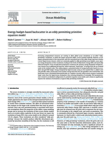
RAMSETRAM 100 1000 5500RAM 100 Installation specificationsWARNINGDo not exceed the specifications. The warranty on your unit will be void if theinstallation exceeds the recommended specifications.All Sliding Gate Operators are factory presetfor (LH) Left Hand Installations.GATEFigure 1Concrete PAD CONSTRUCTION3” MINDimensions given for the pad are based on soil bearing shear of 2000 P.S.F. These figures may have tobe adjusted depending on local soil conditions.WALL1. Construct form for mounting pad according todimensions shown in Figure 1, 2 and 3.6”MIN5”5 3/4”2. Locate mounting pad according to dimensionsgiven in illustration.3. Level top edge of form.4. Set reinforcing bars and wire mesh.5. Mix concrete, pour mixture into form. Level andfinish surface after pouring is complete.4”24”6 1/2”6. Allow pad to cure for 48 hours, and remove forms.TOP vIEWFigure 2GATE ShOWN CLOSEDConduit for lowvoltage wiresConduit forpowerLh FRONT INSTALLATIONconcrete18”11 3/4”Mark centers andinstall four 1/2-13UNC Red-headAnchor BoltsConduit forMaster-Slave18” x 18” x 24”Concrete PadTOP vIEWFigure 3GATEShOWN OPENconcrete 7 1/4”18”BASEOPERATORLh FRONT4 1/2”INSTALLATION3” MINCLTAILGATE4”GATEWallWall6”24”4” MIN4”6www.ramsetinc.com
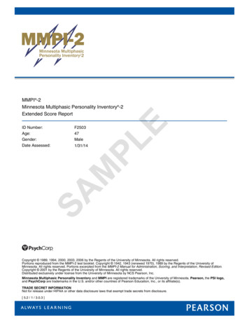
RAMSETRAM 100 FRONt InstallationFRONT INSTALLATIONGATE SHOWN ClosedRAM 100 1000 5500Figure 4Tail on gate requiredTAILWALL5 3/4”13 7/8”6” minFoot Pedal ReleaseWARNINGWe do not recommend use of the foot pedal on installations with steep inclines. Alwaysmake sure the gate is secured when using the foot pedal to avoid sudden movementsfrom the gate. Make sure to show the end-user proper safety precautions when using thefoot pedal.After proper use of the foot pedal, be sure to lightly kick the pedal towards the right side to spring the pedalup and re-engage your gate.Figure 5Gate EngagedGate DisengagedPadlock(optional use)NOTE: Your operator will not respond until your gate is properly engaged.www.ramsetinc.com7
RAMSETRAM 100 1000 5500ram 1000/ ram 5500 Installation specificationsWARNINGDo not exceed the specifications. The warranty on your unit will be void if theinstallation exceeds the recommended specifications.All Sliding Gate Operators are factory presetfor (LH) Left Hand Installations.Figure 6Concrete PAD CONSTRUCTIONDimensions given for the pad are based on soil bearing shear of 2000 P.S.F. These figures may have tobe adjusted depending on local soil conditions.1. Construct form for mounting pad according todimensions shown in Figure 6, 7 and 8.2. Locate mounting pad according to dimensionsgiven in illustration.3. Level top edge of form.4. Set reinforcing bars and wire mesh.5. Mix concrete, pour mixture into form. Level andfinish surface after pouring is complete.6. Allow pad to cure for 48 hours, and remove forms.TOP vIEWFigure 7GATE ShOWN CLOSEDLh FRONT INSTALLATIONconcrete18”13 1/4”Mark centers andinstall four 1/2-13UNC Red-headAnchor BoltsTOP VIEWFigure 8GATESHOWN OPENconcrete 8 5/8”18”BASEOPERATORLH FRONT4 1/2”INSTALLATION3” om
RAMSETram 1000/ ram 5500 Types of InstallationsFRONT INSTALLATIONGATE SHOWN ClosedTail on gate requiredRAM 100 1000 5500Figure 9InsidePropertyTAILOutsidePropertyCENTER INSTALLATIONGATE SHOWN Fully OpenFigure 10No tail on gate requiredInsidePropertyTop ViewFront ViewOutsidePropertyWARNING:USE ONLY CHAINGUARDED PULLEYSREAR INSTALLATION GATE SHOWNFully OpenFigure 11No tail on gate requiredInsidePropertyWallTop ViewHidden WallFront ViewWARNING:OutsidePropertyUSE ONLY CHAINGUARDED PULLEYSwww.ramsetinc.com9
RAMSETLoop SENSOR INSTALLATIONRAM 100 1000 5500Ramset Gate Operators should always be installed with non-contact sensing devices such asLoop Detectors, Photo Eyes or the equivalent.WARNINGA non-contact sensor (photoelectric sensor or equivalent) and a contact sensor (edgedevice or equivalent) is required on each individual installation to comply with UL325.Reversing Loops on the ground floor, prevents gate from closing when vehicle is in loop area.Exit Loops on the ground floor, opens gate when vehicle crosses loop area.Figure 12Gate Travel AdjustmentTurn power off before attempting adjustmentTo adjust gate travel, depress spring loaded bracket and spin each Adjustment Nut to the required position(Figure 13, 14). L.E.D. must turn on to indicate position open or close when limit switch is activated by limitswitch adjustment nut.Ram 100Figure 13Ram 1000 / 5500Figure 14AdjustmentNutsAdjustmentNutsDepress spring loaded bracketto free adjustment nuts10Depress spring loaded bracketto free adjustment nutswww.ramsetinc.com
RAMSETThree pushbuttons are located under the dip switches for operation of the gate (see Figure 15). The opening,stop and closing buttons can be utilized to set limit switches and verify proper system operation wheninstalling or servicing an operator.OpeningPressing this button will cause the gate to open.L.E.D.’s light up when Opening,Closing or StoppedStopPressing this button will cause the gate tostop moving.Figure 15“Intelligate” Control BoardClosingPressing this button will cause the gate to close. Reset E.R.D. BoardPush all three pushbuttons for approximately5 seconds. All three L.E.D.’s should blink.Figure 16MASTER / SLAVE INSTALLATION(RH) Right Hand operation requires Dip Switch(C7) "Left/Right" to be ON.Dip Switch “C”www.ramsetinc.com11RAM 100 1000 5500PUSHBUTTON CONTROLS
RAMSETDIP SWITCH CONFIGURATIONRAM 100 1000 5500Figure 17“Intelligate” Control BoardDIP SWITCH “A”Dip Switch “A” 1, 2 & 3;AUTOMATIC TIMER TO CLOSE GATE‘0’ is “OFF”Switch123Gate Open Duration:11160 seconds11045 seconds10130 seconds10015 secondsDip Switch “B” 3; “CONSTANT WARN”01110 seconds01005 secondsUsed with jP2 “Relay Connections”: pins 7 & 8.Triggers a relay, for an alarm or light (not included), to be active anytime the gate is in motion.00100 seconds000Disabled - command required to closeDip switch A4 works with Dip switch B8A4B8SensitivityOFFOFFMost SensitiveONOFF1/2 Hp — Medium SensitivityOFFON3/4 Hp — Medium SensitivityONONLeast SensitiveDIP SWITCH “B”Dip Switch “B” 1; Not in use at this time.Leave in the ‘Off’ position.12Used with jP2 “Relay Connections”: pins 7 & 8.Triggers a relay, for an alarm or light (not included), for 3 seconds before the gate will move in any direction.‘1’ is “ON”Dip Switch “A” 4 - 1/2 hP ERDDIPDip Switch “B” 2; “PRE WARN”Sw.Function:ONTriggers the relay on jP2 pins 7 & 8 for 3 seconds.OFF Regular working conditionsSw.Function:ONTriggers the relay on jP2 pins 7 & 8 while the gateis movingOFF Regular working conditionsDip Switch “B” 4,5,6 & 7; Not in use at this time.Leave in the ‘Off’ position.Dip Switch “B” 8 - 3/4 hP ERDDip switch B8 works with Dip switch A4DIPA4B8SensitivityOFFOFFMost SensitiveONOFF1/2 Hp — Medium SensitivityOFFON3/4 Hp — Medium SensitivityONONLeast Sensitivewww.ramsetinc.com
RAMSETDIP SWITCH CONFIGURATIONDip Switch “C” 1; “SECURE CLOSE”Sw.Dip Switch “C” 5; “CLOSE DELAY”Function:One second delay on the closing of the gate.OFF Normal OperationONWhen power is lost, then regained, control boardchecks status of the gate. If open and safety devices are cleared, gate will close automatically.Dip Switch “C” 6; “OPEN DELAY”One second delay on the opening of the gate.Dip Switch “C” 7; “LEFT / RIGhT”Sw.WARNING:OFF Left hand installations - All operators come factoryWhen installing or servicing an operator, make sure switch“C” 1 is ‘Off’. If switch “C” 1 is ‘On’, the gate will move whenpower is applied and severe injury may occur.Dip Switch “C” 2; “FULL REv ERD”Changes how long a gate will reverse when an obstruction ismet when closing.Sw.ONFunction:ONRight hand installations - Reverses motor & limitswitches without moving any wires.Dip Switch “B” 8; Not in use at this time.Leave in the ‘Off’ position.Function:Reverses until the open limit is reachedOFF Reverses for 2 seconds and stops again.Dip Switch “C” 3; “RADIO CYCLE”Sw.Function:OFFNormal Operation - gate only opens and closes onthe limit switches. If the gate is in travel then it willalways open.ONCycle mode - gate opens and closes on the limitswitches, but if in travel, then it will stop with a firstcommand and reverse with a second command.Dip Switch “C” 4; “ONE PASS”Sw.Function:OFFNormal Operation - fully opens and closesONOne pass mode - The gate will open until “the reversing loop” is initially activated and then cleared,the gate will then close. If the “reversing loop”is then activated again, before the gate is fullyclosed, the gate will stop until the “reversing loop”is cleared, then continue to close.www.ramsetinc.com13RAM 100 1000 5500DIP SWITCH “C”
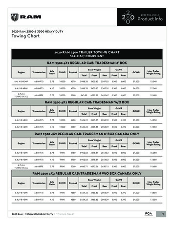
RAMSETTerminal strip ConnectionsRAM 100 1000 5500Figure 18RadioReceiverLimit Switches14www.ramsetinc.com
Terminal strip ConnectionsTerminal # 1 - Common:Low voltage common. Terminal # 2 - Rev loop:Stops the gate from closing. If the gate is open,it holds the gate open. If the gate is closing, itstops and reopens the gate. If the gate is closed,the gate will remain closed. The function can bealtered with Dip Switch “C” 4 (see “Dip SwitchConfiguration”). Used with loop detectors, photoeyes, safety edges etc. Becomes active with aclosed contact to common.Terminal # 3 - Close:Closes the gate. Used with three button stationsor pushbuttons. Becomes active with a closedcontact to common.normal operation. If triggered twice beforereaching a limit switch, the alarm will sound for6 minutes and the control board will not acceptany commands. After the 6 minutes the 24 VDC isremoved from the alarm connection and the boardresets to normal operation.Terminal # 9 and 10 - Limit 1 & Limit 2:Direction depends on Dip Switch “C” 7 (See “DipSwitch Configuration”). Stops the motor frommoving in one direction. These wires are preset infactory and should not be moved. Becomes activewith a closed contact to common.Terminal # 11 and 12 - Common:Low voltage common.Terminal # 13 - 24 VAC:Provides 24 VAC for peripheral accessories.Terminal # 4 - Firebox:Opens the gate. Used with fire department keyswitches & controls. Opens with closed contactto common. Closes immediately when closedcontact on common is removed.Terminal # 14 and 15 - Mag (-) & Mag ( ):Supplies 24 VDC to a Magnetic Lock when thegate is closing or closed. If gate is opening oropened, then no power is supplied. Leave openif not used.Terminal # 5 - Exit:Opens the gate. Used with loop detectors, photoeyes, keypads, phone entry systems, three-button stations etc. Becomes active with a closedcontact to common.Terminal # 16 - m brake:Used ONLY on the Ram 50 Operator. If whilethe gate is closed someone or something tries tomanually open the gate without a proper signal(keypad, exit loop, radio signal ), the motor willlock up for 6 minutes. After the 6 minutes, theoperator will then secure close the gate.Terminal # 6 - Phantom:Keeps the gate open when the open limit switchis activated. Used with loop detectors. Becomesactive with a closed contact to common.Terminal # 7 - radio:Operation depends on dip switch “C” 3 (See “DipSwitch Configuration”). Used with an RF receiveror pushbutton. Becomes active with a closedcontact to common.Terminal # 8 - Edge:When triggered the gate will stop. The gate willremain stopped until the detector is cleared. Oncethe detector is cleared, the operator will resumeTerminal # 17 and 18 - Motor 1 & Motor 2:Supplies power to the motor. Direction dependson Dip Switch “C” 7 (see “Dip Switch Configuration”). These wires are preset and connected inthe factory and should not be moved.Terminal # 19 and 20 - AC Hot & Neutral:110 VAC or 220 VAC to power the operator.Voltage is predetermined at factory and cannot bechanged by the installer or technician.www.ramsetinc.com15RAM 100 1000 5500RAMSET
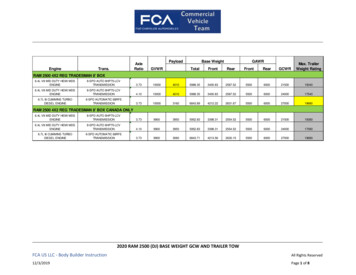
RAMSETIntroduction:Ramset’s “Intelligate” Control Board workswith Sliding, Swinging and Overhead vehiculargate operators. It is controlled by a programmable microprocessor that reads and preciselyexecutes all functions of the Control Board.The Control Board is powered by a separatemounted 24 VAC transformer. This allows nonecessary board modifications between 110VAC and 220 VAC single-phase applications.Some of the functions of the Control Boardare: 0 - 60 seconds automatic close timer, selfadjusting E.R.D. with low and high setting,constant warning, prewarning, secure close,one pass, open & close delay, left/right handoperation, plug-in loop detectors and RS485three wire master/slave connection.Figure 19Reverse LoopPower TransformerExit Loop40VA.Relay ConnectionsIndicator lights, alarms and sirens.plug-inplug-inPhantom Loopplug-inRAM 100 1000 5500ramset “Intelligate” Control BoardjP103 Button StationjP9jP2MicroprocessorReprogrammable, controlsall functions of the operator.DipswitchesAutomatic Timer, Prewarn,Constant Warning, Secure Close,Full Reverse ERD, Radio Cycle,One Pass, Low / High ERD,Adjustment, Close Delay,Open Delay and Left / Right.ERDjP3Self adjusting, with lowand high adjustments.jP11jP7Foot Pedal PlugStops the motor from runningwhile the foot pedal is engaged.3 Button StationOpen - Stop - CloseMaster / Slave PlugSynchronizes movement between twogates. 3 wires (A-, B- and Common).Standard ConnectionsReverse Loop, Fire Box, Exit Loop,Phantom Loop, Radio, Edge Sensor,24 VAC and Magnetic Lock.16www.ramsetinc.com
RAMSETWire board connections1,2) 24 VAC power.Connection from external transformer topower Control Board.JP3 - 3 Button:1) Open 2) Stop 3) Close 4) CommonUsed with a 3-button station to open,stop, and close the gate. The open and close arenormally open connections and the stop is a normally closed connection, remove jumper wire whenconnecting 3 button station. Common and stop arealso used with a photo eye used to protect thebackplane of the operators.JP11 - Foot Pedal Plug:JP2 - Relay Connections:1) 24 VDC.2) 24 VAC3) 5 VDC4) Fully Open-N.O.5) Relay Common6) Fully Closed-N.C.7-8) Constant/Prewarn9-10) E.R.D. Alarm.If E.R.D. is triggered twice before reaching a limit,24 VDC is supplied to sound an alarm (included withoperator).Fully Open N.O. (works with relay common)Relay rated at 125 VAC, 2 amps. Normally open connection. Open contact occurs until the open limit istriggered. When the open limit is triggered, a closedcontact occurs.Relay Common - Relay rated at 125 VAC, 2 amps.Stops the motor from running whilethe foot pedal is engaged.The common of the Fully Closed N.C. relay and theFully Open N.O. relay.Fully Closed N.C. (works with relay common)JP7 - Master/Slave plug:1) A 2) B 3) CommonUsed to synchronize the operation between two gates. A three-wire, Shielded cable isneeded to run from the A, B, & Common (JP7) ofthe master P.C.B. to the A, B, & Common (JP7) ofthe slave P.C.B.Relay rated at 125 VAC, 2 amps. Normally closedconnection. Closed contact occurs until the closedlimit is triggered. When the closed limit is triggered, anopen contact occurs.JP10 - Loop Inputs:1-2) Reverse 3-4) Exit 5-6) PhantomUse with ILD-24s, Loop wires shouldbe connected to this plug.JP4, JP5 & JP8 - Reverse, Exit & PhantomSensor:Used with the Ramset ILD-24 plug-in loopdetector. The Loop wires should be connected intothe “LOOP INPUTS” plug.www.ramsetinc.com17RAM 100 1000 5500JP9 - Input Power:
RAMSETParts DiagramRAM 100 1000 5500RAM 100Figure 01939142171016413818172444www.ramsetinc.com14
RAMSETParts DiagramFigure 215212RAM 100 1000 5500RAM 1000 RAM 637154023381918833349204432www.ramsetinc.com19
RAMSETbill of materials for: Ram 100 RAm 1000 ram 5500Part #1800-00-00RAM 100 1000 5500Item20PART DESCRIPTIONChassis - Ram 100RAm 100RAm 1000RAm 5500111112800-00-01Chassis - Ram 1000/55003800-02-03Gear Reducer - Size 43, Ratio 30:1 (C-Face)4800-02-06Gear Reducer - Size 60, Ratio 30:1 (C-Face)5800-04-00Motor, C-Face - 120 VAC 1/2 HP6800-04-02Motor, C-Face - 120 VAC 1 HP7800-06-08Sprocket - 41B12 x 1/2"8800-06-09Sprocket - 41B15 x 3/4"111119800-12-03Shaft, Limit Switch - 1" - 14 x 10 3/4" (6 1/2" of thread)10800-12-04Shaft, Limit Switch - 1/2" - 11 x 10 1/4" (6 3/8" of thread)111800-14-00Cover, Polyethylene - Ram 100112800-14-01Cover, Polyethylene - Ram 1000/55
5 RAM 100 1000 5500 RAMSET www.ramsetinc.com MODEL RAM 100 RAM 1000 RAM 5500 MAX. GATE LENGTh 20 feet 45 feet 45 feet MAX. GATE WEIGhT 700 lbs 1000 lbs 2500 lbs CYCLES Continuous Continuous Continuous CAPACITOR Aerovox 65µƒ, 240 V, 50/60